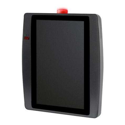
Estyma IGNEO Touch User guide

Installers manual
EG-Multifuel


Table of contents
Chapter 1. Safety 4
1.1 Disposal of waste electrical and electronic equipment.......................................................................5
Chapter 2. Technical Specifications 6
Chapter . Installation and servicing instructions 7
.1 Dimensions.................................................................................................................................................... 7
.2 Electrical installation................................................................................................................................... 7
. Working conditions..................................................................................................................................... 7
.4 Assembly........................................................................................................................................................ 8
.5 Connections................................................................................................................................................... 9
.6 Switching between photo/exhaust sensor in CAN IO BIG................................................................9
.7 Connection diagram.................................................................................................................................... 9
.8 Firmware updates...................................................................................................................................... 12
.9 Access levels............................................................................................................................................... 12
.10 Configuration changes........................................................................................................................... 12
.11 Factory settings....................................................................................................................................... 12
Chapter 4. Service menu/function descriptions 1
4.1 Boiler............................................................................................................................................................ 1
4.2 Burner........................................................................................................................................................... 1
4.2.1 BLOWER POWER MODULATION...........................................................................................14
4.2.2 TEST FUEL MASS..........................................................................................................................14
4. Heating......................................................................................................................................................... 14
4.4 Hot water..................................................................................................................................................... 15
4.5 Solar heating............................................................................................................................................... 15
4.6 Buffer............................................................................................................................................................ 15
4.7 Sound alarm................................................................................................................................................ 15
4.8 Configuration.............................................................................................................................................. 15
4.9 Out test........................................................................................................................................................ 16
4.10 Statistics.................................................................................................................................................... 16
4.11 Net.............................................................................................................................................................. 16
Chapter 5. Alarms 17
5.1 Detailed descriptions................................................................................................................................ 17
www.estyma.pl 3
EGM-ENG-I 20171123

Installer's manual IGNEO touc
Chapter 1. Safety
ATTENTION! Electrocution risk!
Turn off power on t e electric switc board before assembly or disassembly.
Carefully read t e instruction before use.
Keep t e instruction manual and consult it w en using t e device.
Abide by t e rules of use and warnings written in t e instruction manual.
C eck if t e device isn't dammaged. W en in doubt, don't use t e device and contact t e retailer.
If you encouter situations not mentioned in t e instruction manual, or you are in doubt about safe usage
of t e device, please contact t e retailer.
Pay attention to any warning symbols on t e device or packaging.
T e device must be used in accordance wit intended use.
T e device is not a toy, keep out of c ildrens reac .
Under no circumstances allow c ildren to play wit any part of t e packaging.
Keep small parts (screws, wall plugs etc.) away from c ildren. Small elements supplied wit t e device can
be a c oking azard.
Do not modify mec anical or electrical parts of t e device. It can result in abnormal functioning,
malfunctions, errors and failure to comply wit regulations.
Do not put anyt ing into any openings in t e device. It can cause s ort circuits, electric s ock, fire or
complete destruction of t e device.
Do not allow t e device to come in contact wit water, moisture or dust. It can cause s ort circuits,
electric s ock, fire or complete destruction of t e device.
After turning off t e device using touc panel, it can still be under power.
T is regulator is designed as a part of a boiler, not a standalone device.
T is device requires a proper ventilation. Do not cover any ventilation oles to assure a proper air circulation.
For inside use only, unless stated ot erwise.
Do not expose to impacts or vibrations.
Before installing verify if electrical grid parameters are wit in specifications.
To ensure electric s ock protection, verify t at t e device is grounded. It must be connected wit a 3 pin
socket. T e power socket must be installed by an aut orized electrician.
Verify if t e device will not cause power grid overload. Do not connect t e device to a circuit containing
electric motors and ot er impulse disruption sources (freezers, was ing mac ines etc.)
Before connecting any wires or external devices, turn off mains supply.
To completely turn off t e device, pull t e plug out of t e socket. Especially if it will not be used for an
extended amount of time.
T e power cord must be protected from damage. It must not be stepped on and no objects s ould be
placed on it.
T e regulator must be installed by t e boiler producer. Any electrical connections must comply wit
circuit diagrams and local standards and regulations.
Additional safety devices must be used to protect t e boiler and eating elements from eventual regulator
4www.estyma.pl
EGM-ENG-I 20171123

C apter 1. Safety
malfunctions or software errors.
T is device as no replaceable parts. All servicing and repair, apart from cleaning and circuit breaker replacement
(electrical grid disconnected) and c anging settings must be performed by an aut orized profesionals.
Before any service activity disconnect t e device from any power sources.
Do not use gasoline, solvents or ot er c emicals for cleaning. It can damage t e panel. Use soft clot instead.
If t e power cord is damaged, do not use t e device. Damaged cable must be replaced wit one wit t e
same parameters by t e service department.
Settings must be adjusted to a type of boiler and fuel, accomodating for all ot er conditions. Incorrect
settings can result in failure. In extreme cases it can lead to life t reatenig situations.
T e regulator is ment to be installed by a boiler producer. Before using it in a device, t e producer must
verify t at it's compatible wit t e boiler type, and its use will not cause any danger or malfunctions.
1.1 DISPOSAL OF WASTE ELECTRICAL AND ELECTRONIC EQUIPMENT
T is electronic device consists of partly recycleable materials. It as to be disposed of by taking it to a designated
used electric and electronic equipment collection point or a retailer. It s ould not be mixed wit general ouse old
waste.
www.estyma.pl 5
EGM-ENG-I 20171123

Installer's manual IGNEO touc
Chapter 2. Technical Specifications
TECHNICAL DATA
Module power suppl voltage ~230V/50Hz ±10%
Module power consumption <6VA
Temperature measurement accurac ±4ºC
Sensors NTC 10kΩ B25/85=3877K±0,75% VISHAY BC components
Ambient temperature limits 0-60ºC
Humidit 5-95%, no condensation
Software class A
MODULE OUT UT CA ACITIES
DO1-DO11 100W
AO1-AO4 150W
6www.estyma.pl
EGM-ENG-I 20171123

C apter 3. Installation and servicing instructions
Chapter 3. Installation and servicing instructions
.1 DIMENSIONS
.2 ELECTRICAL INSTALLATION
Carefully read t e manual before use.
Installer s ould ave tec nical experience.
Connections made wit copper wire s ould be suitable for operation up to +75ºC.
All connections must comply wit electrical connection diagrams and national or local regulations for electrical
connections.
CAUTION! This device must be connected to a separate electric circuit equipped with an
appropriate overcurrent switch and a differential current switch
. WORKING CONDITIONS
T is device is designed to be used only in enclosed spaces.
Work environment must meet certain conditions:
1. It must be free of excessive moisture, flamable gasses and corosive factors.
2. Do not place next to ig power electric appliances, electric devices and welding equipment.
3. T e room temperature must not drop below 0ºC or exceed 60ºC. Humidity must fall between 5%
and 95%, wit out condensation.
www.estyma.pl 7
EGM-ENG-I 20171123

Installer's manual IGNEO touc
.4 ASSEMBLY
T e operating panel is designed to be placed on a mounting wall or plate.
Plate t ickness s ould not exceed 3mm.
Minimal dept of a mounting
ole is 30mm.
Precise ole and panel
dimensions are s own on t e
left.
Remember to secure t e panel in place by using t e locking frame.
IO modules are designed for a standard DIN 35mm rail.
CAUTION! For securit and reliabilit reasons the device must be accessible onl to authorized
and properl trained personel.
8www.estyma.pl
EGM-ENG-I 20171123
Panel
Mounting ole

C apter 3. Installation and servicing instructions
.5 CONNECTIONS
T e regulator must be connected to sensors and devices necessary for proper operation.
CAUTION! Do not connect PE to neutral (N).
CAUTION! An hardware manipulation requires disconnecting the power suppl . Connections
should be carried out b a person with an appropriate authorit in this regard.
Remember to connect t e operating panel to an IO
module. Connection met od is s own on t e left.
.6 SWITCHING BETWEEN PHOTO/EXHAUST SENSOR IN CAN IO BIG
CAN IO BIG module allows to c oose between an ex aust temperature sensor or a burner brig tness sensor, bot
connect to t e IN12 input. To select an ex aust sensor, open t e IO module and place t e jumper over t e pins
s own below. To select t e brig tness sensor, take it off.
A – Jumper off
– burner p oto sensor
B – Jumper on
– ex aust temperature sensor
.7 CONNECTION DIAGRAM
S own below are typical connections for CAN IO . T e details of inputs and outputs are specified in t e tables.IO
www.estyma.pl 9
EGM-ENG-I 20171123

Installer's manual IGNEO touc
10 www.estyma.pl
EGM-ENG-I 20171123

C apter 3. Installation and servicing instructions
CAN IO MODULE IN UTS
IN UT CH+HW
IN1 Boiler temperature sensor
IN2
IN3 HW temperature sensor
IN4 CH circuit 1 temperature sensor
IN5 Room temperature sensor
IN6 Blower RPM sensor +12V DC
IN7 Calorimeter
IN8 Boiler operation permission
IN9 Fuel reserve capacity sensor NPN, NO, +12V DC
IN10
IN11 Exterior temperature sensor
IN12 Ex aust temperature sensor
CAN IO MODULE OUT UTS
OUT UT CO+CWU
DO1 CH circuit 1 pump
DO2 CH circuit 1 mixer - Open
DO3 CH circuit 1 mixer - Close
DO4
DO5 Igniter
DO6 Heat exc ange cleaner, As removal
AO1 Blower
AO2 Fuel conveyor — Burner
AO3 Fuel conveyor — Storage
A04 HW pump
STB STB safety switc
NNeutral permanent
N1'Neutral disconnectable, eg. by STB
PE Protective
CAUTION! 1. STB switch will disconnect N1 outputs after detecting boiler overheating. In result all
devices connected to N1 outputs will also be disconnected.
2. Hall sensor is compatible onl with CAN IO ver. 2.0 or higher.
. Boiler operation permission is compatible onl with CAN IO ver. 3.2 or higher.
www.estyma.pl 11
EGM-ENG-I 20171123

Installer's manual IGNEO touc
.8 FIRMWARE UPDATES
To update t e firmware, copy t e installation file into a main directory of an empty microSD card. T e card must be
formatted using FAT32 file system. T e installation filename must begin wit letters FW, wit t e .bin filetype. To begin t e
update, dissconnect t e device from t e power supply and put t e microSD card in t e slot at t e back of t e device.
To insert t e microSD card:
1. Move t e cover to t e rig t
and lift it up.
2. Place t e microSD card in
t e slot.
3. Close t e cover and move
it to t e left to lock t e
card in place.
After powering up t e device, t e update process s ould start automatically. All previous settings will be
preserved. Start of t e installation will be indicated by a blinking red LED. T e green LED will indicate t at t e
process as ended successfully. Wait for t e main screen to appear and disconnect t e device. After taking out
t e memory card and connecting a power supply, start t e device again. T e device s ould be ready to use.
.9 ACCESS LEVELS
To provide safety and streamline t e user experience, more advanced menu options are idden be ind advanced access
levels. To c oose t e access level, enter main menu and c oose Menu level (PIN). T is manual describes only options and
parameters avaliable to installers. For user settings see t e user manual. T ere are two levels available to installers:
level 0 – user
default access level,
t e system reverts to t is level after a period of
inactivity
level 1 – installer
code 0900,
Active installer's permissions are indicated by a wrenc icon wit a number 1. It's s own at t e top rig t corner of
t e screen. Option lists are also separated by t e same symbol to differenciate between user and installer options.
.10 CONFIGURATION CHANGES
After making c anges in t e Configuration menu, especially if t e IO module or source as c anged, it is required to
restart t e device by disconnecting it from t e power supply.
CAUTION! Wait 10 seconds before turning off the power suppl to ensure that the changes
were saved correctl .
.11 FACTORY SETTINGS
To reset t e device to factory settings, go to Menu level (PIN) (see section 3.9) and set t e value to 6666.
12 www.estyma.pl
EGM-ENG-I 20171123

C apter 4. Service menu/function descriptions
Chapter 4. Service menu/function descriptions
4.1 BOILER
LEVEL 1
NAME DESCRI TION
Min pump temperature [°C] Minimum water temperature, above w ic t e boiler pumps can be turned on.
Pump overrun time [min] T e boiler pump will work for set amount of minutes after t e burner switc es off
to protect t e boiler from over eating.
Exchanger silence mode T e eat exc anger cleaning will be turned off during silence ours.
Silence hours from T e time of silence ours start.
Silence hours to T e time of silence ours finis .
Min return temperature [°C] W en t e water temperature falls below t is value, return valve is opened to eat
t e water.
Mixing valve time [s] Mixing valve full opening time.
Fuel reserve stop [kg] W en calculated fuel amount falls below t is value, burner is turned off to protect
t e conveyor from emptying.
4.2 BURNER
LEVEL 1
NAME DESCRI TION
Blower power modulation [%] T is setting allows to s ape t e blower RPM curve as a function of burner power.
For more details see c apter 4.2.1.
Feeding max [s] Maximum fuel delivery time.
Fuel predose [s] Time of supplying t e initial dose of fuel during ignition.
Blower firing up power [%] Blower power percentage during ignition.
Blower in incandescing [%] Blower power percentage during kindling.
Blower burning off [%] Blower power percentage during burning off.
Incandescing time [min] T e lengt of t e kindling p ase.
Incandescing fuel [%] Regular fuel dose percentage during kindling.
Burning off time [min] T e lengt of t e burning off p ase.
Test fuel mass [kg/h] T e amount of fuel supplied by a conveyor per our of uninterrupted work. For
more details see c apter 4.2.2
Fuel calorific value [kWh/kg] T e calorific value of t e fuel used.
Lambda control Enables or disables t e oxygen modulation using Lambda sensor.
Ox gen power 30% Oxygen percent value for 30% burner power.
Ox gen power 100% Oxygen percent value for 100% burner power.
Extra exhaust fan T e power of t e additional ex aust fan.
www.estyma.pl 13
EGM-ENG-I 20171123

Installer's manual IGNEO touc
4.2.1 BLOWER POWER MODULATION
T is menu allows to set t e blower RPM profile as a
function of burner power. T e values can be individually
set for 20%, 40%, 60%, 80% and 100% of blower
power by moving t e nodes up or down and fine tuning
t e value by 1 using arrows on t e rig t.
4.2.2 TEST FUEL MASS
To calculate a proper fuel level, it is required to set t e fuel supply rate in kg/ . To determine t is value, run t e
conveyor test for 15 minutes (see Out test) gat ering t e fuel into a previously weig ted container. Weig t e
pellet t at came out of t e conveyor tube accounting for tare weig t. Multiplying t e fuel weig t by four will
result in t e kg/ ratio (15min x 4 = 60min).
4. HEATING
LEVEL 1
NAME DESCRI TION
Source Determines t e energy source for CH.
Increase source temperature [°C] T e amount of degrees by w ic t e temperature of t e source must be ig er
t an t e CH temperature.
Room sensor Room sensor type: None | CTP1 | CTP2 | videROOM | t ermostat.
Max temp. [°C] Maximum calculated temperature for CH.
HC sensor Specifies if CH sensor is used in t e system.
Temp. HC corr. factor [°C/ °C] Set CH temperature correction per 1°C of difference between room temperature
set vs measured. Example: Parameters: The correction value=6°C,
room temperature=20°C, room temperature=20,5°C.
Value: 20-20,5=-0,5 which means the C set value is corrected by -0,5*6°C=-3°C
Max Tout pump comfort [°C] Maximum outside temperature at w ic circulation pump can operate w en t e
eating is set to comfort program.
Max Tout pump econom [°C] Maximum outside temperature at w ic circulation pump can operate w en t e
eating is set to economical program.
CH temperature lowering [°C] After reac ing required room temperature, t e CH temperature is lowered by t is value.
Min HC temp. pump [°C] Minimum calculated water temperature, above w ic t e CH pumps can be turned on.
Mixing valve time [s] Mixing valve opening time.
Pump constant On – t e pump keeps working after reac ing set room temperature. T e calculated CH
temperature value is lowered (w en using CH and room temperature sensor).
Off – After reac ing set room temperature t e pump is turned off.
14 www.estyma.pl
EGM-ENG-I 20171123

C apter 4. Service menu/function descriptions
4.4 HOT WATER
LEVEL 1
NAME DESCRI TION
Source Determines t e energy source for HW.
Increase source temperature [°C] T e amount of degrees by w ic t e source temperature is ig er t an t e HW
temperature.
Delta temperature pump on [°C] Minimum temperature difference between t e source and HW above w ic t e
pumps can be turned on.
Max temp. [°C] Maximum temperature of t e eated water.
4.5 SOLAR HEATING
LEVEL 1
NAME DESCRI TION
Liquid specific heat [kJ/(kg*K)] Specific eat (in kJ/(kg * °C)) of t e liquid used in solar installation.
Max water temp. [°C] Maximum temperature of t e eated water.
Max solar temp (alarm) [°C] Maximum solar collector temperature above w ic t e alarm is turned on, and t e
safety procedures are activated.
Min solar temp (alarm) [°C] Minimum solar collector temperature below w ic t e alarm is turned on, and t e
safety procedures are activated.
4.6 BUFFER
LEVEL 1
NAME DESCRI TION
Min pump temperature [°C] Minimum upper buffer temperature, above w ic t e pumps of all circuits (HW,
CH, etc.) wit a source set to buffer can be turned on.
Automatic temp. top [°C] A c oice between manual and automatic adjustment for a upper buffer
temperature requirement. Automatic adjustment calculates t is setting based on
requierments of ot er circuits.
Increase source temperature [°C] T e amount of degrees by w ic t e source water temperature will be increased
compared to t e upper buffer temperature.
Delta temperature pump on [°C] Minimum difference between t e source temperature and t e buffer temperature
above w ic t e pumps can be turned on.
4.7 SOUND ALARM
Turns on/off t e alarm sound.
4.8 CONFIGURATION
LEVEL 1
NAME DESCRI TION
Autoconfiguration Automatically detects connected modules and devices.
Main module IO Main IO module selection.
Heating circuits number T e amount of central eating circuits.
Outside temperature sensor Exterior temperature sensor selection.
Hot water Determines if t e ot water circuit is used.
www.estyma.pl 15
EGM-ENG-I 20171123

Installer's manual IGNEO touc
Solar heating Determines if t e solar water eating is used.
Buffer Determines if t e bufer is used.
Lambda module Determines if t e Lambda module is used.
Fuel reserve sensor Determines if t e fuel reserve sensor is used.
Fuel tank capacit [kg] Determines t e main fuel storage capacity.
Fuel tank reserve [kg] Determines t e fuel level below w ic t e fuel reserve alarm will turn on.
Return to boiler sensor Determines if t e boiler return sensor is used.
Profile number Switc ing between eating system profiles:
Profile 1 – CH+HW+Buffer | Profile 2 – CH1+CH2+HW.
Boiler pump Determines t e boiler pump type: loading pump | return guard
Cascade master Determines if t e cascade master is used.
Pressure sensor Determines if t e boiler pressure sensor is used.
T p czujnika spalin Determines t e ex aust sensor type: KTY84-130 | PT1000
Additional fuel storage Determines if t e additional fuel storage is used.
4.9 OUT TEST
Every output can be set to one of t ree modes:
A – Automatic,
output operates normally
OFF – Output off,
settings and programs are ignored
ON – Always on,
settings and programs are ignored
4.10 STATISTICS
Statistics useful during troubles ooting and maintenance.
4.11 NET
S ows t e state of all connected CAN modules.
16 www.estyma.pl
EGM-ENG-I 20171123

C apter 5. Alarms
Chapter 5. Alarms
5.1 DETAILED DESCRIPTIONS
Code 1 Boiler sensor m lfunction
T e panel received a boiler temperature sensor disconnection/s ort circuit. It may be caused by sensor
malfunction or connection cable damage.
Code 2 Boiler overhe ting
Boiler temperature exceeded t e maximum value.
www.estyma.pl 17
EGM-ENG-I 20171123

Notes:


roduced by:
estyma electronics
Gajewo, Aleja Lipowa 4
11-500 Giżycko
OLAND
tel. +48 87 429 86 75
www.estyma.pl
Other manuals for IGNEO Touch
1
Table of contents
Popular Control Panel manuals by other brands
Notifier
Notifier NFS2-640/E Operation manual
Core
Core TOUCH S 10” quick start guide
Johnson Controls
Johnson Controls IFC-200 operating instructions

Roiscok
Roiscok RP208CN User's and installer's manual

Klimosz
Klimosz HoGas duo instruction manual

elsner elektronik
elsner elektronik WS1 Style Series Brief Instruction
Tyco Fire Product
Tyco Fire Product CWSI CP-3500D instruction manual

Immergas
Immergas HSCP Instructions and Recommendations
Monicon
Monicon GTR-100B user manual
AERF
AERF MONO 1H instructions

salmson
salmson Easy Control MS-L 1x4kW Series Installation and starting instructions
Victron energy
Victron energy Color Control GX manual

