Etatron eTwin Instructions for use

NORME DI INSTALLAZIONE, USOE MANUTENZIONE
OPERATINGINSTRUCTIONS AND MAINTENANCE
NOTICED’INSTALLATION, EMPLOI ET ENTRETIEN
NORMAS DE INSTALACIÓN,USO Y MANUTENCIÓN
NORMAS DE INSTALAÇÃO, USO E MANUTENÇÃO
IT
UK
FR
ES
PR
eTwin March 2020
Edition
GEBRAUCHSANWEISUNG
DE
UNI EN ISO 9001-2008


ENGLISH 1
TABLE OF CONTENTS
GENERAL RULES ............................................................................................................................3
Warnings ...............................................................................................................................................3
Symbols used in the manual ...................................................................................................................3
Transport and handling ..........................................................................................................................3
Intended use of the device ....................................................................................................................3
Risks.....................................................................................................................................................3
Dispensing harmful and/or toxic liquids ................................................................................................4
Assembling the pump.............................................................................................................................4
Disassembling the pump .......................................................................................................................4
ETWIN SERIES METERING PUMP ..................................................................................................4
General features of ETwin pumps ..........................................................................................................4
Operating principle of peristaltic pumps ................................................................................................5
Operating principle of electromagnetic pumps .......................................................................................5
Main features .........................................................................................................................................5
Technical features of peristaltic version ................................................................................................6
Technical features of electromagnetic version .......................................................................................6
Materials in contact with additive in peristaltic version .........................................................................6
Materials in contact with additive in electromagnetic version..................................................................6
Main additional functions .......................................................................................................................7
INSTALLATION ................................................................................................................................8
ETWIN .............................................................................................................................................. 9
Control Panel ........................................................................................................................................9
DIAGRAM OF THE ELECTRICAL CONNECTIONS ........................................................................9
DESCRIPTION OF THE SCREEN ..................................................................................................11
Access to probe setting, configuration and calibration menus ...............................................................11
PRIMING FUNCTIONS ...................................................................................................................12
SET-POINT CONFIGURATION MENU ...........................................................................................12
Setting pH, Rx Chlorine parameters ......................................................................................................12
PROBES CONNECTION ................................................................................................................14
pH probe connection ............................................................................................................................14
Rx probe connection ............................................................................................................................15

2ENGLISH
Cl probe connection .............................................................................................................................15
PROBES CALIBRATION MENU .....................................................................................................15
pH probe calibration ............................................................................................................................16
Rx probe calibration ............................................................................................................................16
Cl probe calibration .............................................................................................................................17
MANUAL MODE SETTING MENU ..................................................................................................17
SETTINGS MENU............................................................................................................................18
Relay outputs ......................................................................................................................................19
Inputs ..................................................................................................................................................21
Timer ...................................................................................................................................................21
Alarms .................................................................................................................................................23
mA output............................................................................................................................................25
Visualization of the probe mVs .............................................................................................................25
Activation delay ...................................................................................................................................26
pH priority ........................................................................................................................................... 26
Temperature ........................................................................................................................................26
PPM scale values .................................................................................................................................27
Clock ...................................................................................................................................................27
Password .............................................................................................................................................28
Setting the language ............................................................................................................................29
Reset ...................................................................................................................................................29
MAINTENANCE...............................................................................................................................29
INTERVENTION ON ETWIN PUMPS IN CASE OF FAILURE.........................................................30
Mechanical failures ...............................................................................................................................30
Electrical faults ...................................................................................................................................30
DRAWINGS .....................................................................................................................................31
Peristaltic and Electromagnetic Pump Exploded Drawings .....................................................................31

ENGLISH 3
GENERAL RULES
Warn ing s
Read the warnings below carefully. They provide important information regarding safe installation, use and maintenance.
Store this manual with the utmost care for future reference.
The device complies with directive no. 2014/30/EU “electromagnetic compatibility” and no. 2014/35/EU “low voltage
directive”.
The device is built in a professional manner. Its endurance and electrical and mechanical reliability will be more efcient if it is
used properly and maintenance is carried out on a regular basis.
ATTENTION: Any work or repairs inside the device must be carried out by qualied and authorised personnel. We assume no
liability due to failure to comply with this rule.
WARRANTY: 2 years (excluding parts subject to normal wear, namely: valves, ttings, pipe collars, tubes, filter and injection
valve). Improper use of the device will void this warranty. The warranty is understood as ex-works or authorised distributors.
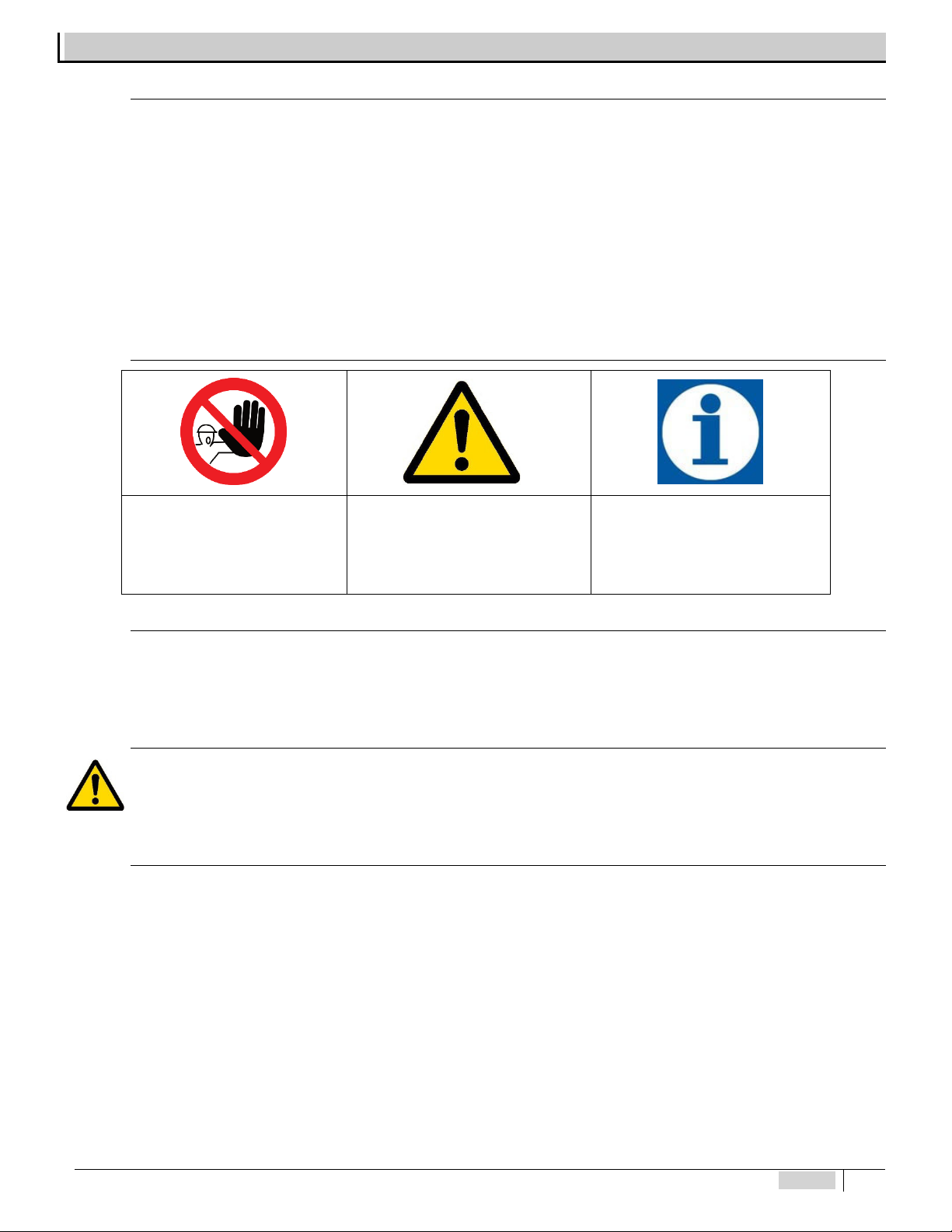
Symbol s use d in the man ua l
FORBIDDEN
Precedes information regarding
safety. Indicates a forbidden
operation.
ATTENTION
Precedes very important text to protect
the health of persons exposed or the
machine itself.
INFORMATION NOTE
Precedes information concerning use
of the device.
Tra ns por t an d han dl ing
The device must be transported as indicated on the box. Shipping by any means, even if free of carriage of the purchaser or
recipient, is carried out at the purchaser's risk. Claim formissing materialsmust be made within 10 days ofarrival ofthe goods. Whereas
defective material within 30 days of receipt. If the device is to be replaced, it must be agreed upon with authorised personnel or the
authorised distributor.
Inte nd ed u se of t he de vi ce
The device must only be used as expressly intended and namely for dosing liquids. Any other use is considered improper and
therefore dangerous. The device is not intended to be used for any applications not foreseen during the design stage. For further
explanations, the customer must contact our ofces for information as to the type of pump in their possession and its correct use. The
manufacturer shall not be held liable for any damage resulting from improper, erroneous or unreasonable use.
Ris ks
After removing the packaging, check the integrity of the device. If in doubt, do not use it and contact a qualied technician. The
packing materials (such as plastic bags, polystyrene, etc.) must not be left within reach of children since they are potentially dangerous.
Before connecting the device, make sure that the rating corresponds to that of the mains. The rating is displayed on the adhesive
label on the device itself
Execution of the electrical system must comply with the standards that dene professional workmanship in the country where the
system is made.
Use of any electrical device implies observance of some fundamental rules. In particular:
�do not touch the device with wet or damp hands or feet (e.g. swimming pools);
�do not leave the device exposed to atmospheric agents (rain, sun, etc.)
�do not allow the device to be used by children or persons incapable of using it without surveillance.

4ENGLISH
In case of failure and/or malfunctioning of the device, switch it off and do not tamper with it. For any repairs, please contact our
service centres and request use of original spare parts. Failure to comply with the above can jeopardise the safety of the pump.
If you decide to no longer to use a device, it is recommended to make it inoperable by unplugging it from the mains.
�Make sure it is switched off electrically (both polarities), disconnecting the conductors from the contact points of the mains by
opening the omnipolar switch with at least 3 mm between the contacts.
�Appropriately eliminate any pressure in the peristaltic pumps and supply pipes, paying the utmost attention.
�Eliminate all the liquid in the pinch tubes.
In case of any leaks in the hydraulic system of the pump (breakage of injection valve, lter, pipes), you must stop the pump,
depressurise the supply pipe and then proceed with maintenance operations using appropriate safety measures (gloves, goggles,
overalls, etc.).
Dispensing harmful and/or toxic liquids
The following rules, along with the instructions in this booklet, must be kept in mind to avoid personal harm or property damage
due to contact with harmful liquids or the intake of toxic fumes:
�Always work as recommended by the manufacturer of the liquid being used.
�Use appropriate personal protective equipment
�Check that the hydraulic part of the pumps has no damage or breakage. Only use the device if in perfect working order.
�Use tubes suited to the liquid and the operating conditions of the plant, inserting them, if necessary, into protective PVC pipes
�Before deactivating the device, you must neutralise the hydraulic part with an appropriate reagent.
Assembling the pump
All metering pumps manufactured by us are usually supplied fully assembled. For further explanations, please consult the
attachment at the end of this manual where exploded drawings of the pumps and all parts with relative nomenclature are displayed in
order to have a complete picture of the equipment. These drawings are anyhow required to recognise the malfunctioning or defective
parts.
Disass em bl in g th e p um p
You must always pay the utmost attention when disassembling the pump or anyhow before performing maintenance on it. We
recommend consulting the attached drawings and referring to the previous chapter “RISKS” before beginning any operation.
ETWIN SERIES METERING PUMP
Ge ne ral f ea t ur es of E Tw in pu mp s
ETwin is an easy to use device, consisting of a pair of metering pumps (electromagnetic or peristaltic) and electronics capable of
measuring the chemical values of water in a swimming pool, such as pH, redox potential (mV) and chlorine concentration (in ppm).
These parameters can be controlled by dosing appropriate additives with the pumps supplied with eTwin. The materials eTwin is made
of are suited for dosing the most common products used in the swimming pool industry.
See the instructions for use supplied by the manufacturer of the chemicals for the selection and correct use of the
additives used in swimming pools.
�Default settings
•eTwin pH – RX Set-point = 7.2pH; intervention: ACID,Set-point= 700mV; intervention: OXIDANT
•eTwin Cl – pH Set-point = 7.2pH; intervention: ACID, 1 ppm (scale 0 - 2 ppm); DIRECT intervention
•eTwin 2 pH Set-point = 7.2pH; intervention: ACID on both measurements

ENGLISH 5
�Range of values:
•pH: 0÷14
•Redox: -1000 ÷ +1400 mV
•PPM: 0÷2, 0÷10, 0÷20, 0÷200 ppm
•Temperature 0÷100 °C (PT100)
Operating pr in ci pl e of p er is ta lt ic pu mp s
By peristalsis we mean the propulsive motion of automatic contractions inside a channel or pipe, from whence the term peristaltic
action. Through the mechanical simulation of biological peristalsis, rollers compress the walls of a pipe forming a seal during their
movement, then the compressed part of the pipe goes back to its original shape thus suctioning uid by means of the negative pressure
created. The fluid follows the roller until the pipe is no longer compressed. At this point, a second roller is already compressing the pipe
to avoid a backow, pushing the initial dosage of uid out of the pump and repeating the suction action. Rollers mounted on special
rotors allow the pump to run continuously thanks to their inlet/outlet action.
Operating principle of electromagnetic pumps
The metering pump operates by means of a PTFE (Teflon®) diaphragm mounted on the piston of an electromagnet. When the
piston of the electromagnet is attracted, it creates pressure on the pump body thus ejecting liquid from the supply valve. When the
electric pulse is nished, a spring brings the piston back to its initial position owing liquid through the suction valve. The pump needs
no lubrication and practically no maintenance thanks to its easy use. The materials used to build the pump make it t for dispensing
chemically aggressive liquids. The metering pump was designed for ow rates from 2 to 5 l/h and pressures from 5 to 6 bar according
to the model.
Main fea tu re s
�Device manufactured according to standards
�Chassis made of: Polypropylene
�Designed for tting level probe
�Standard electric power supply (uctuations of a maximum ±10% are allowed): 230 V a.c. 50/60 Hz single phase.
Fig. 1 – Views and dimensions – peristaltic version Fig. 2 – Views and dimensions – electromagnetic version

6ENGLISH
Te ch ni cal fe atu re s of pe rista lt ic v ers io n
Type
MAX
Flow rate
[l/h]
MAX
Pressure
[bar]
Weigh
t
[Kg]
Dimensions [mm] Absorbed
Power
[W]
Rotation
Speed
[RPM]
Pipe
[ODxID]
[mm]
Height Width Depth
eTwin
1.5 1.5 1.5 270 235 140 15 20 4 x 6
3 1.5 1.5 270 235 140 15 40 4 x 6
Te ch ni ca l fe ature s of e le ctr om ag ne tic v er si on
Type
MAX
Flow rate
[l/h]
MAX
Pressure
[bar]
Weigh
t
[Kg]
Dimensions [mm] Absorbed
Power
[W]
Injections
[pul/1’]
Pipe
[ODxID]
[mm]
Height Width Depth
eTwin
2.0 6.0 3.5 270 235 148 65 120 4 x 6
5.0 5.0 3.5 270 235 148 65 120 4 x 6
Materials in co nt ac t w it h additive in p er is ta lt ic v er si on
�Pinch tube: Santoprene®
�Bottom filter: Standard – Polypropylene®
�Injection valve: Standard – Polypropylene®
�Suction pipe: PVC Cristal®
�Supply pipe: Polyethylene®
Materials in co nt ac t with add it iv e in e le ct ro magnetic v ersion
�Pump body: PVDF (polyvinyl chloride)
�O-Ring: Viton®
�Valves: Ceramic
�Bottom filter: Standard – Polypropylene®
�Injection valve: Standard – Polypropylene®
�Suction pipe: PVC Cristal®
�Supply pipe: Polyethylene®

ENGLISH 7
Main a dd it io na l fu nc ti on s
Function Description
LEVEL ALARM
Operating if enabled, the opening or closing of the contact on the level probe indicates
that the additive in the tank has nished; the instrument deactivates the relays of the
set points and displays an alarm. Possibilityof choosingbetween normally open contact
(default setting) or normally closed. Possibility of choosing triggering of the level alarm
for each measuring channel.
PROXIMITY SENSOR
The input can be activated to connect the proximity sensor which detects the ow in
the probe holder and enables triggering of the instrument. Possibility of choosing
between normally open contact (default setting) or normally closed. Possibility of
choosing to associate it to one or both pumps (default).
MINIMUM AND MAXIMUM ALARM
You may set the minimum and maximum thresholds of the measured quantity, beyond
which the instrument triggers an alarm. Possibility of choosing triggering of the
minimum and maximum alarm for each measuring channel. You may also associate
enabling of the alarm relay.
OVERDOSAGE ALARM
You may set an operating time limit for the pumps, beyond which, if the set-point values
are not reached, an alarm triggers and the device shuts down. The count includes the
service time, considering the actual operation of the pumps, therefore excludingpauses
in proportional operation. The relay output is always enabled.
ACTIVATION DELAY
It denes a time, starting from switch on, during which the device does not dose or
measure. When switched on, a countdown is displayed indicating the time remaining
until the measuring channelis activated. One for each measuring channel. Thisfunction
is useful when the sensors need a certain amount of time before detecting a reliable
measurement. Different delay values can be chosen for each measuring channel.
CLOCK To set the date and time. These parameters must be set if timer mode is activated.
TEMPERATURE PROBE A two-wire PT100 probe may be connected to the instrument to compensate the
measurement.
ALARM RELAY SERVICES OUTPUT
This can be enabled through the menus of all the alarms, remotely indicating any alarm
situations.
Features: 1 exchange – 250V a.c. 5A (resistive load) and 1A (inductive load).
OUTPUT CURRENT (mA)
The instrument has an output in current (4-20 mA), directly proportional to the reading
of the measurement made by the instrument. By acting on the DOWN ARROW key
while it is displayed, you may view the current value present on the output.
TIMER Weekly and daily timer. 4 daily ON/OFF cycles. Set to the minute.
MULTI-LANGUAGE Language of the menus: Italian/English/German/Spanish/Portuguese/French
PASSWORD A password can be set to separately protect CALIBRATION, SET-POINT, SETTINGS
and STANDBY
RESET Possibility of performing the reset to restore the default settings
PRIMING It is possible to operate the pumps regardless of the measurement value detected by
the probes, for example to prime them during the installation procedure

8ENGLISH
INSTALLATION
Install the pump in a dry area away from heat sources at a
maximum ambient temperature of 40 °C, while the minimum
operating temperature depends on the liquid to be dosed which
must always remain in the uid state.
Comply with standards in force in the different countries
regarding the electrical installation (Fig. 2). If the power cord
does not have a plug, the device must be connected to the
mains by means of an omnipolar disconnecting switch with at
least 3 mm between the contacts. All the power circuits must
be interrupted before accessing the connection devices.
Fig. 3 – Electrical connection
The device is supplied with a bracket to x it to the wall
and relative plugs for masonry walls. Always use a plug
appropriate to the available support. The layout of the
holes to be drilled on the support is displayed in
Fig. 1 – Views and dimensions – peristaltic version
Fig. 2 – Views and dimensions –
electromagnetic version
Fig. 4 – Drilling support bracket
Position the pump as in the gure, considering that it must be secured both
below and above the level of the liquid to be dosed within a maximum limit of 2
m. The injection points must always be higher than the liquid to be injected. For
liquids which let out aggressive fumes, do not install the pump above the tanks
unless they are watertight.
Insert the tubes all the way on the relative tapered couplings and block
them with the specic ring nuts. Donot make elbows on the supply and suction
pipe. Apply a 3/8” gas female tting on the piping of the plant to be treated, at the
most suitable point to inject the product to be dosed. This tting is not included in
the supply. Screw the injection valve in the tting using Teflon® as a gasket.
Connect the tube to the tapered coupling of the injection valve and block it with
the specic ring nut. The injection valve is also a check valve.
Fig. 5 – Standard installation

ENGLISH 9
ETWIN
Control P an el
The following gure depicts the control panel with the description of the functions of the different keys.
1 Increase values button
2 Decrease values button
3 MENU - ESC button
4
Calibration (CAL) of
instrument and OK
conrmation button
5Set-point display and
setting button
Fig. 6 – Control Panel 6 Digital screen
DIAGRAM OF THE ELECTRICAL CONNECTIONS
To connect the accessories and peripheral devices to the pump, remove the front cover, acting on the two plastic screws on the
sides of the cover with a at headed 5mm (at least) screwdriver to reach the terminal board.
The terminal board consists of spring terminals for quick coupling of the wires. Press the square “slotted” pin with a small at
headed screwdriver and insert the stripped wire in the corresponding terminal. ATTENTION: exert slight pressure on the spring pin
to avoid irreparably damaging the terminal board.
Pass the cables through the rubber cable glands on the wall of the cover, using a screwdriver to remove the thin internal closing
septum. Pay attention to perforation of the cable gland and wear appropriate protective equipment (gloves).
Fig. 7 – Opening terminal board cover and position of probe connectors

10 ENGLISH
The probe connectors are located at the bottom of the device as shown in
Fig. 7 – Opening terminal board cover and position of probe connectors
.Set-points 1 and 2 are always matched respectively to measuring channels 1 and 2 on all eTwin pump models and
versions.
Once the cables are connected, close the cover and delicately pull any extra cable out through the cable glands. ATTENTION:
tighten the gasket as much as possible but not excessively so as not to damage the plastic screws.
The following table shows the allocations of measuring channels 1 and 2 according to your eTwin version.
Measurement - Version pH - Rx Chlorine - pH pH - pH
Measurement 1 pH Chlorine pH
Measurement 2 Rx pH pH
Table 1 -Conguration of measurement channels of different eTwin versions
Right side terminal block J17
Fig. 8 – RIGHT terminal block J17
No. Description
1
RS485 (not enabled)
2
3
4
5 Pump 1 Level Probe Input (-)
6 Pump 1 Level Probe Input (+)
7 Pump 2 Level Probe Input (-)
8 Pump 2 Level Probe Input (+)
9 Proximity Sensor Input (-)
10 Proximity Sensor Input (+)
11 External command (-)
12 External command (+)
13 mA output (-)
14 mA output (+)
15 PT100 input (-)
16 PT100 input (+)
17 +5V power supply. Chlorine pot. probe
18 +5V power supply. Chlorine pot. probe

ENGLISH 11
Left side terminal block J16
Fig. 9 – LEFT terminal block J16
No. Description
1 Relay L1 NO
2 Relay L1 NC
3 Relay L1 Common
4 Relay L2 NO
5 Relay L2 NC
6 Relay L2 Common
7 Relay L3 NO
8 Relay L3 NC
9 Relay L3 Common
10
Not connected
11
12
13 Relay L5 NO
Alarm
14 Relay L5 NC
15 Relay L5 Common
Terminals 9-10 (proximity sensor) and 11-12 (external command) of the RIGHT terminal block called “J17” are short-
circuited with removable jumpers. The default triggering mode for these input is set at NO (normally open). To leave the behaviour of
the device unchanged, the jumpers can be removed and switched to NC (normally closed). For the operating modes, see the chapter
on settings of the external inputs.
DESCRIPTION OF THE SCREEN
Access t o pr ob e s et ti ng , co nf ig ur at io n and c al ib ra ti on m en us
While browsing the different menu items on the right side of the screen, a series of icons are enabled indicating which keys can
be pressed in that particular context.
you may press the MENU/ESC key
you may press the CAL/OK key
you may press the ARROW keys
In measuring mode, when icons 1, 2, 3 are lit it means that the relative relay is activated.
Instrument screen MEASURING
Instrument screen in PAUSE
When the instrument is switched on, it stores the prior condition, PAUSE OR MEASURING.

12 ENGLISH
PRIMING FUNCTIONS
To facilitate pump priming, it is equipped with the PRIMING function. It is recommended to open the purge bypass on the pump
bodies (for eTwin with electromagnetic hydraulics) during the priming operations. The air purge tting must always be connected to
the relative tube with return to the suction tank.
This function can be activated in any operating mode (MEASURING or IN PAUSE) as follows:
•Press and hold the UP ARROW key for left hydraulics, or the DOWN ARROW key for right hydraulics.
•After about 5 seconds, the pump begins to dispense injections at the priming frequency (120 pul/min for electromagnetic pumps,
at maximum speed for peristaltic pumps) until the operator releases the UP/DOWN ARROW key. The following screen appears
on the display while pressing the key:
•The PRIMING function can be activated even if the pump is protected by PASSWORD.
SET-POINT CONFIGURATION MENU
Setting pH, R x Chlorine parameters
The following tables show the sequence of operations to set the operating parameters of the measurement on channel 1, Ph or
Cl. The same process can be applied to channel 2 of the measurement (pH, Rx, Cl).
The current and stored values are highlighted with a dot to the right of the value.
Default set-point values 7.20 pH, 700mV, 1,50ppm.
In the set-point programming menu of the pH, Rx and Chlorine (PPM) modes, the following can be set:
•SET-POINT: intervention value and mode
•INTERVENTION TYPE: denes the eld of application of the instrument
•HYSTERESIS: range around the set-point value within which the pumps are not activated. When the measurement leaves this
interval, the pumps are activated
•TEMPERATURE: compensation of the measurement relating to the temperature (only for pH if enabled in MANUAL mode – see
chapter Temperature)

ENGLISH 13
•CONSTANT: the pumps operate at a xed frequency or speed until they reach the set-point value.
•PROPORTIONAL: the time-pause intervals or the injection frequency decreases as the set point value approaches to limit
oscillations of the measurement
•INTERVAL: intervention value for the maximum PROPORTIONAL dosage
•MAXIMUM FLOW RATE: full-scale value on which the proportionality of the dosage is regulated: 30÷300 sec. (peristaltic), 0÷100
% (electromagnetic)
The selection of the “INTERVENTION TYPE” parameter depends on the type of product dispensed.
•pH: If an acid product is used, the pump intervening with acid doses by pH values higher than the set-point to
lower the value to the desired point. On the other hand for alkaline intervention, with dosing aimed at increasing
the pH value, the pump doses with measures of pH lower than the set-point.
•Rx: If an oxidant product is used (e.g. sodium hypochlorite) the pump intervening with oxidant doses by mV
values lower than the set-point to increase the value to the desired point. On the other hand for reducing agent
intervention, with dosing aimed at decreasing the Rx value, the pump doses with measures of mV higher than
the set-point.
•Cl: If an oxidant product is used (e.g. sodium hypochlorite) the direct intervention pump doses by ppm values
lower than the set-point to increase the value to the desired point. On the other hand for inverse intervention,
with dosing aimed at decreasing the CL value, the pump doses with measures of ppm higher than the set-point.
To conrm the changes, conrm all the parameters in the SETPOINT menu until you go back to the window “PUMP 1 or
2 SET-POINT”. You may exit the menu (from any parameter) without saving the changes by pressing the MENU/ESC button.

14 ENGLISH
PROBES CONNECTION
pH probe connection
The following instructions apply to eTwin pH-Rx or pH-pH models where channel 1 is always allocated to the pH probe input. For
Cl-pH instruments, on the other hand, the pH probe must be connected to the second channel. To get started, connect the probe to the
instrument as indicated in Fig. 10 o 10.1 (depending on the instrument in possession).
1. power cord
2. electrode
3. BNC connector
The pH probe MUST be connected to input 1 allocated for measurement 1, pH, see Fig. 7
Fig. 10 – pH electrode connection (eTwin pH-Rx o pH-pH) Fig. 11.1 – pH electrode connection (eTwin Cl-pH)

ENGLISH 15
Rx probe c on nection
The following instructions apply to all eTwin pH – Rx models. To
get started, connect the probe to the instrument as indicated in Fig.
11
1. Power cord
2. Electrode
3. BNC connector
The Rx probe MUST be connected to input 2 allocated for
measurement 2, Rx,
Fig. 12– Rx electrode connection
Cl probe connection
The instructions in this paragraph apply to eTwin Chlorine - pH
models. The Chlorine probe must be connected to thepump through
the specic cable: having connected BNC, the remaining two cables
must be inserted in the cable gland and connected to the “inputs”
terminal board.
1. Power cord
2. Chlorine probe
3. BNC connector
4. Chlorine probe power cord
PROBES CALIBRATION MENU
To allow the device to correctly detect the parameters of the water to be checked, the probes connected to it must be calibrated.
Either electrodes made of glass or plastic can be used. The instructions for calibrating the probe apply to all eTwin device models and
versions
During the calibration, the pH, Rx and PPM values displayed on the left of the screen represent the real time values of
the reading of the probe, while those displayed on the right of the screen are the values of the BUFFER solutions used to
calibrate the different points.
Attention: if calibration is not carried out correctly or the readings are not even made on the instrument, they could have
serious errors with non-negligible consequences on the health and safety of the users.
To access the CALIBRATION menu, press for about 5 seconds.
Part
number
Connection
ASO0001701 Connect the power cords of the probe
to terminals 17 (+5V (brown wire) and
18 (-5V white wire) of terminal board J8
(right terminal board)
ASO0001702
ASO0001603
ASO0001604
ASO1000101
Connect the power cord of the probe to
terminal 17 (+5V – positive RED)
ASO1000102
ASO1000201
ASO1000202

16 ENGLISH
pH probe calibration
The following steps show how to calibrate the pH probe. To perform the
operations, you must have two vials of pH 7 and pH 9 buffer solutions of reference (the
solutions are not included in the supply and can be requested separately).
The parameter of the buffer solution (shown on the right of the display) can be
changed using the ARROW keys, if you do not have the buffer solutions corresponding
to the default settings (pH7 and pH9).
pH procedure:
•Dip the electrode in the pH 7 buffer solution
•Wait for the value at the left of the screen to stabilise
•Conrm by pressing OK
•Wait 90 seconds (according to displayed countdown)
•Dip the electrode in the pH 9 buffer solution
•Wait for the value at the left of the screen to stabilise
•Conrm by pressing OK
•Wait 90 seconds (according to displayed countdown)
At the end of the calibration, the instrument detects the PROBE QUALITY
parameter, with the percentages indicating the wear conditions of the probe.
The possible results are: 100%, 75%, 50%, 25%, CALIBRATION ERROR. The last
parameter means that the calibration was not successful due to an error in the
procedure, or that the probe is to be considered no longer usable.
Rx prob e c al ibration
The following steps show how to calibrate the Rx probe. To perform the operations,
you must have a vial of 650 mV buffer solution of reference (the solution is not included
in the supply and can be requested separately).
The parameter of the buffer solution (shown on the right of the display) can be
changed using the ARROW keys, if you do not have the buffer solution corresponding
to the default setting (650 mV).
Rx procedure:
•Dip the electrode in the mV 650 buffer solution
•Wait for the value at the left of the screen to stabilise
•Conrm by pressing OK
•Wait 90 seconds (according to displayed countdown)
At the end of the calibration, the instrument detects the PROBE QUALITY parameter,
with the percentages indicating the wear conditions of the probe.
The possible results are: 100%, 75%, 50%, 25%, CALIBRATION ERROR. The last
parameter means that the calibration was not successful due to an error in the
procedure, or that the probe is to be considered no longer usable.

ENGLISH 17
Cl probe calibration
Before performing the calibration, you must modify the PPM VALUES SCALE
parameter (see relative menu) based on the chlorine probe used.
See the instructions attached to your probe for the preliminary connection
and preparation operations of the sensor and relative maintenance.
To perform the calibration operations, you must have chlorine-free water and
then the same water with a known content of chlorine.
Attention: this procedure requires that the device be connected to an operating
Chlorine probe installed on the system. The measurement for the calibration must be
made using the plant’s water.
During the calibration, the Chlorine value (PPM) displayed on the left of the screen
is the reading value of the probe, while that displayed on the right of the screen is the
value of the solution of reference.
Install an “active carbon lter” upstream of the probe and have water flow in it for at
least 10 minutes, in order to eliminate traces of chlorine and to perform the calibration of
the rst point.
For the second point, add product and use a photometer or a DPD system to read
the PPMvalues. Then modify the valueof reference according to thatread by the manual
measurement. The following is the sequence of operations to calibrate the probe.
Cl procedure:
•Install the chlorine probe in the probe holder, ow water through the plant,
connect the probe electrically and wait for it to polarise (approximately 2 hours –
see the relative probe manual)
•Install an “active carbon lter” upstream of the plant and have water ow in it for
about 30 minutes
•Wait for the value at the left of the screen to stabilise
•Conrm by pressing OK
•Wait 90 seconds (according to displayed countdown)
•For the second point, remove the “active carbon lter” and use a DPD system to read the chlorine in the plant. Insert the read
value, shifting by using the UP/DOWN arrows (changing the value on the right of the screen) and conrm by pressing OK.
•Wait 90 seconds (according to displayed countdown)
MANUAL MODE SETTING MENU
This configuration is present in all versions. The dosing pump operates at a frequency pre-established by the user
and is included in the following ranges:
•0 ÷ 120 pulses / minute (electromagnetic pump)
•0 ÷ 100% (peristaltic pump) (motor cycle time 300s.)
During the operational phase of the manual function, it is possible to display the pulses / minute (electromagnetic pump), the percentage
of dosage (peristaltic).
To enter the manual function, place the instrument in PAUSE mode, by pressing the keys simultaneously .
Press UP arrow to put the LEFT pump in hand, or the DOWN arrow for the RIGHT pump.
Only one pump or both can be placed in MANUAL at a time.
Use the arrows to make the adjustment. Press the OK button and then the ESC button. The selected pump will go to the frequency /
percentage established by the user.
To exit the MANUAL function, and return to the instrument function (pumps controlled by the measurement of the probes),
just press the ESC key.

18 ENGLISH
SETTINGS MENU
To access the SETTINGS MENU, press for at least 5 seconds both from MEASUREMENT mode and from PAUSE.
The following image shows the list of the different items of the SETTINGS submenu which can be accessed. Since it is a circular
menu, the device stores the last item selected before exiting by pressing . You may scroll the different items using the and
keys and then selecting the concerned item by pressing
*PPM SCALE VALUES menu only included in the eTwin Cl-pH version
The following paragraphs extensively explain the operating procedures for conguration of the auxiliary functions.
Table of contents
Popular Swimming Pool Pump manuals by other brands

Profi-pumpe
Profi-pumpe Pool-Star 1100-1 operating instructions

Jandy
Jandy VS FloPro Series Installation and operation manual

welldana
welldana IH20 Installation and operation manual

Hayward
Hayward Super Pump VS SP2603VSP owner's manual

VERDER
VERDER VP2-HT TIMER Programming instructions

BSVILLAGE
BSVILLAGE INVERPAC TURBO Manual book

Intex
Intex Krystal Clear 638G owner's manual

Pentair Pool Products
Pentair Pool Products SuperFlo brochure

Pentair Pool Products
Pentair Pool Products MAX-E-PRO owner's manual

Xylem
Xylem Goulds Marlow Series instruction manual

Pentair Pool Products
Pentair Pool Products WhisperFlo owner's manual

Blue Wave
Blue Wave FlowXtreme NE4487 manual