ETC EM264 User manual

Electronic Theatre Controls, Inc.
3030 Laura Lane, Middleton, WI 53562
Phone: 608/831-4116 FAX: 608/836-1736
Copyright 1992-95, Electronic Theatre Controls, Inc.
Specifications subject to change. Revised 8-92.
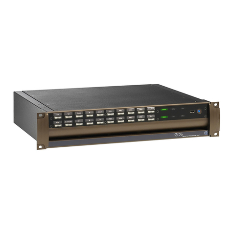
This manual describes ETC’s
EM264
electronics module. The
EM264
uses DMX512 control
signal to control dimmers in ETC
L86 Installation Racks
and
L86 Touring Racks
. Each column
of dimmer modules in a chassis is controlled by an
EM264
near the top of the column.
The
EM264
allows customized dimmer numbering within the chassis. It can compensate for
a mixture of dimmer types within the same chassis and can customize the control curve for
each dimmer. It can also be configured to allow two consoles to control two sets of lights
independently, or two consoles to control the same lights with highest level taking priority.
Generally,
EM264s
in installation racks are factory configured to match the requirements of
your system. For portable racks, standard configurations are available without custom
programming. For more details about standard and customized systems, see
Configuring the
EM264
on page 3.
Additionally, the
EM264
provides optical isolation between input signals and the rest of
your L86 system. The module also isolates the DMX512 input signal between each of the
EM264s
.
There are several important differences between
EM264
s in installation systems and in
touring systems. The following table lists the most important differences:
Touring Rack Installation Rack
Normal output curve Customized output curves
Standard firing mode Optional Quiet mode
Dual DMX512 ports use highest-level input Dual input interaction is programmable
120V output Output voltage is programmable
Any DMX512 number can be starting address Rack number is starting address
Dimmer numbers are sequential, following Dimmer numbers are programmable
starting address
electronics module
U S E R M A N U A L
L86EM264
turn to remove
Electronic Theatre
Controls, Inc.
L86-EM264
reset
enable
disable
DMX 2
DMX 1
power
SIO
error
quiet
high voltage
low voltage
address
table
DMX 2
SIO
quiet
lock
preheat
soft
filter
delay
term-1
term-2
term-S
Front panel
The front panel of the
EM264
contains eight indicator LEDs that provide you with informa-
tion about your dimming system. When you first turn on your system (or press [Reset]) the
EM264
processor runs a series of self tests. If an error is found, the Error, Quiet, High Volt,
or Low Volt LED flashes and all the other LEDs turn off. See the list on page 2 for informa-
tion about the LEDs.

2EM264 Users Manual
Indicator LEDs
Each indicator LED on the
EM264’s
front panel provides specific information about the
operating status of the
EM264
electronics. LEDs have four conditions: Off, On, Blinking
(turning on and off slowly), and Flashing (turning on and off quickly). Generally, a blinking
LED is warning you of a condition that might cause a problem. A flashing LED indicates that
an error has already occurred and the system has stopped operating. The information each
LED provides is described below:
Power
LED On ..............
EM264
is receiving power.
LED Off..............
EM264
is not receiving power.
DMX 1
LED On ..............First DMX512 port is receiving valid DMX512 data.
LED Blinking ......First DMX512 port is not receiving valid DMX512 data.
DMX 2
LED On ..............Second DMX512 port is receiving valid DMX512 data.
LED Blinking ......Second DMX512 port is not receiving valid DMX512 data.
LED Off..............Second DMX512 port is not enabled.
SIO (Serial Input/Output)
LED On ..............Serial Input/Output port is receiving valid data.
LED Off..............Serial Input/Output port is disabled.
Error
LED Flashing .....Error was found in table data or power-up. (Or diagnostic routine is running)
Call your ETC service representative.
LED Off..............No error found.
Quiet
LED On ..............Quiet mode is enabled.
LED Off..............Quiet mode is disabled.
LED Flashing .....Invalid DMX512 address (in portable) or invalid rack number (in installation).
High Volt
LED On ..............Input voltage exceeds 130V AC.
LED Off..............Normal.
LED Flashing .....Input voltage exceeded 135V AC at system startup.
Low Volt
LED On ..............Input voltage is less than 100V AC.
LED Off..............Normal.
LED Flashing .....Input voltage was less than 95V AC at system startup.
Reset button
Press [Reset] to reset the
EM264
to match current rotary and DIP switch settings. Press
[Reset] any time you change the rotary or DIP switches.
Rotary address switches
The rotary switches are used to set starting DMX512 addresses on portable systems and to
set rack numbers on installation systems. They are also used to select self tests and to set
speeds and levels for self tests. See
Configuring the EM264
, page 3, for more information.
DIP switches
The DIP switches are used to select a variety of
EM264
options. See
Configuring the EM264
,
page 3, for more information.

EM264 Users Manual 3
address
Configuring the EM264
DIP switches on the front panel allow you to select
EM264
options. A switch is Enabled
when it is in the up position. It is Disabled when it is in the down position.
Setting starting address
Three rotary switches on the front panel allow you to set the starting address for the
EM264
.
For touring systems, the starting address can be any number from 001 to 512. The starting
address number for each module progresses sequentially from module to module, based on
the size of the first dimmer controlled by each module. For example, in a dimming rack
containing only 1kW dimmers, set the starting addresses to 001, 005 and 009. In. a
dimming rack containing only 2kW dimmers, set the three
EM264s
to 001, 003 and 005. In.
a dimming rack containing only 6kW dimmers, set the three
EM264s
to 001, 002 and 003.
For installation systems, the starting address is the rack number. The dimmer numbering
sequence for each rack is contained in configuration tables stored in the
EM264’s
memory.Valid addresses are 001 to 064 for installation racks. Set the rack address on the
rotary switches. See
Selecting configuration tables
, below.
Addresses 513 to 999 are used for self tests.
Note: If an address outside the available range is selected, the Quiet LED flashes and all
other LEDs turn off until the address is corrected.
Selecting configuration tables
The three DIP switches labeled Table set the
EM264
operating mode. If customized
configuration tables have been programmed at the factory, you must enable all three
switches and the rack address must be set on the rotary address switches. If a standard
configuration is used, set the switches as shown on the chart below.
Note: All EM264s in an installation system are programmed with information for the entire
system. This means that they are interchangeable within the system.
Left Center Right # Mode of operation
Down Down Down 1 All quad 1.2kW dimmers
Down Down Up 2 All dual 2.4 kW dimmers
Down Up Down 3 All single 6.0kW dimmers
Down Up Up 4 All double high 12kW dimmers
Up Down Down 5 All dimmers in consecutive DMX order
Up Down Up 6 Not used
Up Up Down 7 Not used
Up Up Up 8 Custom tables
table
DMX 2
SIO
quiet
lock
preheat
soft
filter
delay
term-1

4EM264 Users Manual
table
DMX 2
SIO
quiet
lock
preheat
soft
filter
delay
term-1
Enabling the second DMX512 port
The
EM264
is equipped with two DMX512 input ports. If the module simultaneously
receives input from both DMX512 sources, it sets dimmer output at the higher of the two
levels.
The second DMX512 port is activated by enabling the DIP switch labeled DMX 2. If you are
only using one input, disable the switch.
Enabling the SIO (Serial Input/Output) port
The SIO port is activated by enabling the DIP switch labeled SIO. The port is turned off by
disabling the switch. If your system is not equipped with the SIO function, leave this switch
disabled.
Enabling Quiet mode
The
EM264
allows you to operate some or all of your system's dimmers in Quiet mode.
Quiet mode can reduce lamp noise significantly in lamps connected to these dimmers.
Available only in
EM264s
in L86 Installation Racks, Quiet mode is most often specified for
certain dimmers at the same time the system's configuration tables are programmed at the
factory.
Enable the DIP switch labeled Quiet to activate Quiet mode for all dimmers programmed to
use the mode. Disable the switch for normal operation.
Warning: Do not connect load types other than incandescent lamps to the dimmer if Quiet
mode is enabled for that dimmer. In Quiet mode, the dimmer may produce a DC voltage
that can damage other types of load.
table
DMX 2
SIO
quiet
lock
preheat
soft
filter
delay
table
DMX 2
SIO
quiet
lock
preheat
soft
filter
delay
term-1

EM264 Users Manual 5
Enabling Lock
Lock protects programmed information in your module. Once you have configured an
EM264
, you should leave it locked at all times. Before a module can be reprogrammed, you
must disable Lock. Lock is activated by enabling the DIP switch labeled Lock. It is turned
off by disabling the switch.
Note: Lock does not affect rotary or DIP switch settings. It protects internal programming.
Enabling Preheat mode
In Preheat mode, the
EM264
maintains all dimmers at a minimal level even when the
dimmer output level is set to zero. This can prolong the life of your lamps. If your rack
contains dimmer modules with indicator lights, Preheat mode makes the indicators glow
slightly at all times. Enable the DIP switch labeled Preheat to activate Preheat mode.
Disable the switch for normal operation.
Note: If you run a blackout while Preheat mode is active, the system blacks out fully for six
seconds, then raises all dimmers slightly to the preheat level.
Enabling Soft Start
Soft Start adds a filter that reduces lamp shock caused by turning a lamp with a cold bulb
on to full. Soft Start checks the bulb to see if it is cold; if it is, Soft Start applies a filter to
protect it. Enable DIP switch 9 to activate Soft Start. Disable the DIP switch labeled Soft
for normal operation.
table
DMX 2
SIO
quiet
lock
preheat
soft
filter
delay
term-1
table
DMX 2
SIO
quiet
lock
preheat
soft
filter
delay
term-1
term-2
DMX 2
SIO
quiet
lock
preheat
soft
filter
delay
term-1
term-2

6EM264 Users Manual
Enabling filtering
The two DIP switches labeled Filter set DMX512 filter levels for the
EM264
, as shown on
the chart below. Four levels of filtering are provided to help stabilize control levels. Filter
settings affect all dimmers.
Setting delay
If DMX512 input is interrupted, the
EM264
holds dimmer levels for either three minutes or
three seconds, then fades outputs to zero. To set the delay for three seconds, disable the
DIP switch labeled Delay. For a three minute delay, enable the DIP switch. The fade takes
five seconds.
Control termination
Three sets of double DIP switches labeled Term-1,Term-2 and Term-s are provided to
allow you to activate the control termination circuit required at the end of the DMX512 and
SIO communication links. Enable all three pairs of termination switches on the highest
numbered
EM264
installed in the highest numbered rack in your system. Disable all three
pairs of switches on the other two
EM264s
in that rack and all
EM264s
in all other racks.
Note: On some installation racks the termination settings may vary. Consult the switch
settings chart in your System Manual before changing termination switches.
DMX
2
SIO
quiet
lock
preheat
soft
filter
delay
term-1
term-2
term-S
quiet
lock
preheat
soft
filter
delay
term-1
term-2
term-S
enable
disabl
e
soft
filter
delay
term-1
term-2
term-S
Left Right Filter selected
Down Down None
Down Up 32 ms
Up Down 64 ms
Up Up 128 ms

EM264 Users Manual 7
Self test mode
EM264
’s Self test mode allows you to run a number of diagnostic self tests. Set the rotary
switches as shown below to select the desired test. Press [Reset] to start the test. When
you press [Reset], all the LEDs flash three times then turn off (except for the Power LED
which stays on throughout all the tests), the
EM264
resets and the self test runs.
Switch settings
Some of the tests allow you to set the speed at which the test runs. The rate is determined
by the setting of rotary switch 3. Set the rotary switch to 0to freeze the test. Settings from
1to 9set the speed from the slowest rate to the fastest rate respectively. In the Level to
all test, the rotary switches allow you to set output levels of zero through 100 percent.
Serial Input/Output (SIO) port test
If the
EM264
is equipped with SIO receiver hardware, this test confirms that the SIO port is
functioning. The optional SIO test module must be installed to run this test. Set the front
panel rotary switches to 810 and press [Reset] to run the test. If the test encounters an
error, the Error LED flashes.
Output chase
This test flashes each of the system’s outputs from 1 through 64, one at a time, to confirm
that all outputs are functioning. Set the front panel rotary switches 1 and 2 to 91 and press
[Reset] to run the test. Adjust the speed of the test by setting rotary switch 3 from 0to 9as
noted in
Switch settings
.
Fade all dimmers
This test fades all outputs simultaneously from off to full and back to off. Set rotary
switches 1 and 2 to 92 and press [Reset] to run the test. Adjust the speed of the test by
setting rotary switch 3 from 0to 9as noted in
Switch settings
.
Fade one dimmer
This test fades each output from off to full and back to off one at a time. Set the front

8EM264 Users Manual
panel rotary switches 1 and 2 to 93 and press [Reset] to run the test. Adjust the speed of
the test by setting rotary switch 3 from 0to 9as noted in
Switch settings
.
Set one dimmer on
This test raises a specified output to full. Set the front panel rotary switches 1 and 2 to 94
and press [Reset] to run the test. Once the test starts, set the number of the desired
dimmer (from 001 to 064) using the rotary switches.
Set level to all dimmers
This test raises all outputs to a specified level. Set the front panel rotary switches 1 and 2
to 95 and press [Reset] to run the test. Once the test starts, use the three rotary switches
to set the level percentage you desire (from 000 to 100).
Watchdog test
The
EM264's
Watchdog function monitors the
EM264
and restarts the processor if it
malfunctions. This test checks the module’s Watchdog function. Set the front panel rotary
switches to 960 and press [Reset] to run the test. The LEDs light, then turn off one at a
time. If the function works, the processor will reset within two seconds. If the test
encounters an error, the Error LED will flash.
Table of contents
Other ETC Control Unit manuals
Popular Control Unit manuals by other brands

maxxess
maxxess eMAX-MR51e Installation Guide and Specifications

RHEINTACHO
RHEINTACHO Stroboscope Control Unit operating instructions

schmersal
schmersal SRB 401EM-115V operating instructions

Flomec
Flomec G2 owner's manual

M-system
M-system R7D-YS2 instruction manual

Realtek
Realtek RTL8763B Series user manual