PG 2 PG 3
READ THIS FIRST:
Check the pack and make sure you have all of the
parts listed on the front of this booklet. If not,
contact the outlet where you bought this product.
This product must be installed by a competent
person in accordance with the current building and
IEE wiring regulations.
As the buyer, installer and/or user of this product it
is your own responsibility to ensure that this tting
is t for the purpose for which you have intended
it. Eterna Lighting cannot accept any liability for
loss, damage or premature failure resulting from
inappropriate use.
This product is designed and constructed according
to the principles of the appropriate British Standard
and is intended for normal domestic service. Using
this tting in any other environments may result in
a shortened working life, for example where there
is prolonged periods of use or higher than normal
ambient temperatures such as lighting public or
shared spaces.
Switch o the mains before commencing installation
and remove the appropriate circuit fuse or lock o
MCB.
This unit is suitable for outdoor use.
This product is suitable for installation on surfaces
with normal ammability e.g. wood, plasterboard
and masonry. It is not suitable for use on highly
ammable surfaces
Before making xing hole(s), check that there are no
obstructions hidden beneath the mounting surface
such as pipes or cables.
Make sure that the xings are strong enough to
support the considerable weight of the tting and
hold it rigidly.
The chosen location of your new tting should allow
for the product to be securely mounted. And safely
connected to the mains supply (lighting circuit).
When choosing the location for your new tting,
ensure that the xings will be anchored in a solid
surface e.g. concrete, brick or a joist—do not x
directly onto panelling, cladding, plasterboard etc.
When making connections ensure that the terminals
are tightened securely and that no strands of wire
protrude. Check that the terminals are tightened
onto the bared conductors and not onto any
insulation.
This tting is double insulated; do not connect any
part to earth.
This product is not intended to be used by children
and persons with sensory, physical and/or mental
impairments that would prevent them from using it
safely.
You are advised at every stage of your installation to
double-check any electrical connections you have
made. After you have completed your installation
there are electrical tests that should be carried out,
these tests are specied in the current IEE wiring and
building regulations.
INSTALLATION:
ISOLATE MAINS BEFORE
CARRYING OUT INSTALLATION
01) Undo the nuts each side at the front of the tting
and lift o the front section of the lantern
02) Using the back cover of the tting as a template,
mark the location of the xing holes.
03) Pierce the rubber grommet in the back of the
tting. Make the hole as small as possible so that
a good watertight seal is maintained when the
cable has been threaded through.
04) Thread the cable through the grommet.
05) Secure the tting to the wall using xings (not
supplied).
06) Make the connections to the terminal block
according to the colour code and symbols:
LIVE - Brown or Red • NEUTRAL - Blue or Black
07) Connect the two wires from the front half of the
lantern to the push terminal block in line with the
colour code and symbols (see g. 4 opposite).
08) Replace the front part of lantern and secure by
tightening the two nuts making sure you have a
rubber sealing washer under both nuts.
09) Restore power.
10) Switch on and product should function.
SPECIFICATIONS:
• Detection range: Approx. 120° (horizontal), Max. 8
metres.
• Duration time: from 5 sec - 5 mins. (adjustable).
• No override facility.
• LUX - adjustable.
LAMP REPLACEMENT:
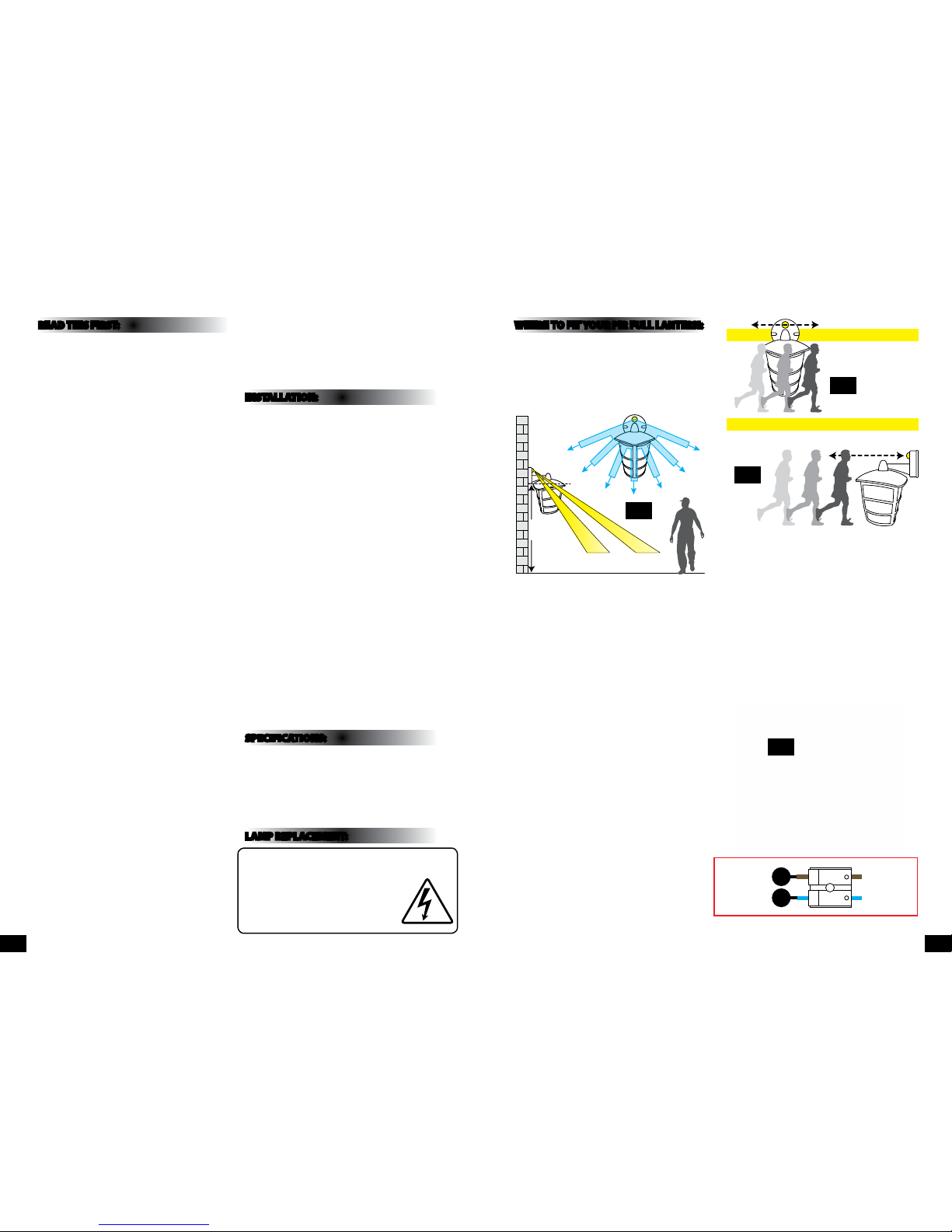
WHERE TO FIT YOUR PIR FULL LANTERN:
To achieve best results we suggest you take the
following points into consideration:
Do not mount on a surface that has vibration.
Ideally the PIR lantern should be mounted 1.8 to 2.5
metres (6 to 8ft) above the area to be scanned (refer
to Fig. 1 below).
To avoid damage to the unit do not aim sensor
towards the sun.
Avoid positioning the sensor unit adjacent to a
bright light source which may prevent the unit from
operating when the lux control is set to operate in
dark conditions.
Avoid nuisance false triggering by directing sensor
away from:
Trees and shrubs
Reective surfaces such as smooth white walls
Swimming pools
Heat sources such as boiler ues
The PIR sensor scanning specications
(approximately 8 metres at 120°) may vary slightly
depending on the mounting height and location.
The detection range of the unit may also alter
with temperature change. Before selecting a place
to install your PIR lantern you should note that
movement across the scan area is more eective
than movement directly towards or away from the
sensor (refer to Fig. 2 above).
If movement is made walking directly towards or
away from the sensor and not across the apparent
detection range will be substantially reduced (refer
to Fig. 3 above).
1.8-
2.5M
4M 8M
120˚
Approx
Fig 1
EFFECTIVE:
Movement
across scan area
LESS EFFECTIVE:
Movement directly in front of
scan area
Fig 2
Fig 3
L N
Blue
(Power Cable)
Brown
(Power Cable)
Blue
(Power Cable)
Brown
(Power Cable)
Fig 4
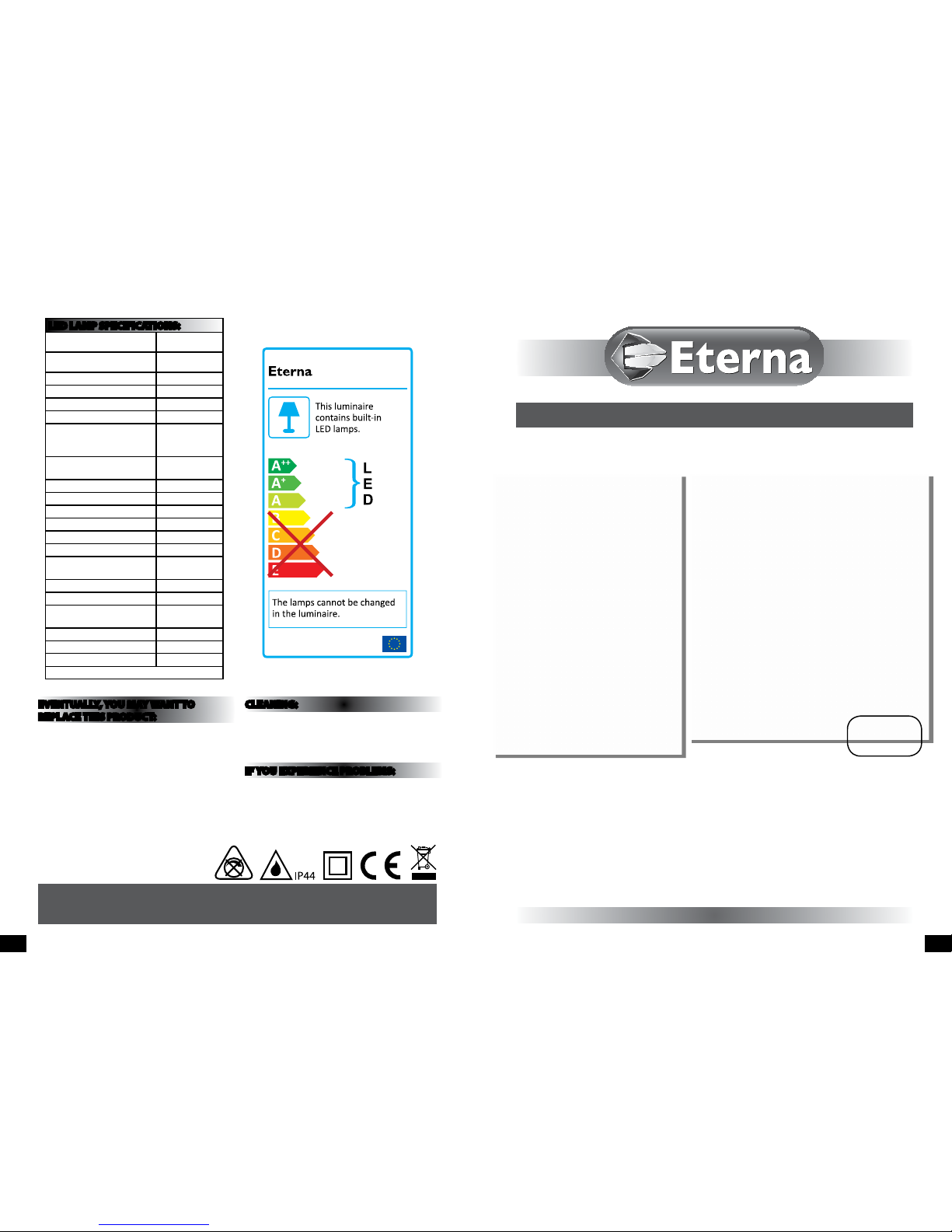
The light source contained in this luminaire
shall only be replaced by the manufacturer,
service agent or a similar qualied person.
CAUTION, RISK OF ELECTRIC SHOCK.
The light source is designed to last the lifetime of the
luminaire.