READ THIS FIRST:
Check the pack and make sure you have all of the
parts listed on the front of this booklet. If not,
contact the outlet where you bought this product.
This product must be installed by a competent
person in accordance with the current building and
IEE wiring regulations.
As the buyer, installer and/or user of this product it
is your own responsibility to ensure that this tting
is t for the purpose for which you have intended
it. Eterna Lighting cannot accept any liability for
loss, damage or premature failure resulting from
inappropriate use.
This product is designed and constructed according
to the principles of the appropriate British Standard
and is intended for normal service. Using this tting
in any other environments may result in a shortened
working life, for example where there is prolonged
periods of use or higher than normal ambient
temperatures.
Switch o the mains before commencing installation
and remove the appropriate circuit fuse or lock o
MCB.
Disconnect the Driver / dimmer from the electrical
supply before ash or high voltage testing.
Do not connect to a circuit which also has inductive
loads connected; switching of inductive loads will
generate spikes which may damage electronic
components within your driver / dimmer.
This unit is suitable for outdoor use.
This product is designed for permanent connection
to xed wiring: this must be a suitable circuit
(protected with the appropriate MCB or fuse).
Before making xing hole(s), check that there are no
obstructions hidden beneath the mounting surface
such as pipes or cables.
Make sure that the xings are strong enough to
support the considerable weight of the tting and
hold it rigidly.
The chosen location of your new tting should
allow for the product to be securely mounted (e.g.
to a ceiling joist) and safely connected to the mains
supply (lighting circuit).
When making connections ensure that the terminals
are tightened securely and that no strands of wire
protrude. Check that the terminals are tightened
onto the bared conductors and not onto any
insulation.
This product must be connected to earth
termination.
This product is not intended to be used by children
and persons with sensory, physical and/or mental
impairments that would prevent them from using it
safely.
You are advised at every stage of your installation to
double-check any electrical connections you have
made. After you have completed your installation
there are electrical tests that should be carried out,
these tests are specied in the current IEE wiring and
building regulations.
OPERATION CHECKS:
Periodic testing should be carried out to ensure
emergency lighting is operating correctly.
Interruption of the supply, causing the tting to be
energised from the battery, should be carried out by
the operation of a local keyswitch or other isolation
device. During this period all ttings should be
examined visually to ensure that they are functioning
correctly. At the end of the test period the supply
shall be restored and all indicator lamps or devices
checked to ensure that the normal supply has been
restored.
DAILY:
Visual inspection of the battery charge LED.
EACH MONTH:
Isolate the power supply for a period sucient to
ensure that each lamp is illuminated. Endorse the
test record form supplied.
ONCE EACH YEAR:
Isolate the power supply and check that the light is
still illuminated after 3 hours. Endorse the test record
form.
Because of the possibility of a failure of the normal
lighting supply occurring shortly after a period of
testing of the emergency lighting system or during
the subsequent recharge period, all full duration
tests shall wherever possible be undertaken
preceding time of low risk to allow for battery
recharge.
NOTE: please keep this instruction booklet and
the test record in a safe place. A re ocer or
other authorised person may want to see your
record of inspection and testing.
INSTALLATION:
01) Choose the location of your new tting giving
consideration to all of the conditions listed above
and the position of the entry points for the mains
supply cable.
02) Put nger in the hole on top of the clip and pull
outwards to release the diuser clips to open up
the tting.
03) Press together the tops of the clips protruding
through the middle of the gear tray and lift the
tray out of the tting.
04) If xing direct to a mounting surface, clear
through the mounting holes on the back of the
tting, visible from the outside, using a 5mm drill.
05) Using the back of the tting as a template, mark
the location of the xing holes on your mounting
surface.
06) If xing directly to a solid surface, drill holes and
insert the plastic plugs supplied.
07) Secure your tting in position using the screws
and washers supplied. Put the washer onto the
screw before xing. If the xings supplied are
not appropriate to your installation, please select
suitable alternatives. Take care not to over tighten
xing screws to prevent damaging the case.
08) Hanging clips are supplied to allow you to
suspend the tting from chains (not supplied).
09) Ensure that the chain is strong enough to support
the weight of the tting and that the tops of the
chains are xed securely to the mounting surface.
10) Pierce the centre of the grommet at the end of
the tting adjacent to the supply wiring. Take
care not to make the hole too large as the tight
t of the gland to the cable is essential for it to
retain its IP rating. Alternatively, t a gland/nut
assembly.
11) Thread the supply cable through the gland.
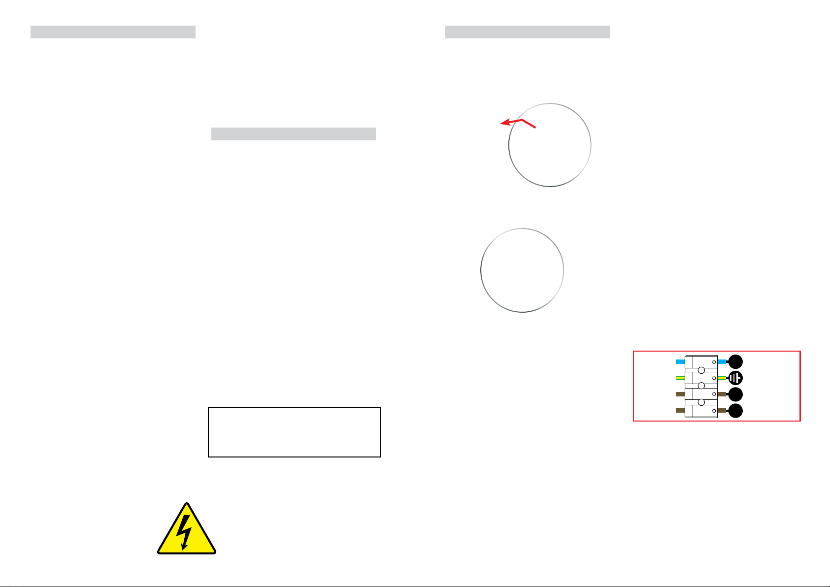
12) Make connections to the terminal block on the
back of the white metal gear tray according to the
following colour code:
Neutral - Blue or Black
Earth - Green and Yellow
PL (Permanent Live) - Brown/Red
SL - (Switch Live) - Brown/Red
13) Adjust the microwave sensor settings as required.
14) Locate the gear tray over the metal clips
protruding from the case and press the gear tray
into position. Ensure that all clips have latched
securely.
15) Hold the diuser in position on the tting so that
it is seated on the soft foam gasket all the way
around.
16) Position the bottom of each clip hook in the lip of
the diuser and press the thumb catches up and
over to lock rmly in position.
17) Restore the power supply and switch on.
NOTE: this unit has a permanent live mains supply,
please ensure you isolate before removing cover.
There may also be a seperate switched supply that
controls the emergency light tting - this also needs
to be isolated.
Yellow/Green EARTH
PL
N
Blue/Black
Brown/Red
Brown/Red
SL
NEUTRAL
PERMANENT LIVE
SWITCH LIVE