READ THIS FIRST:
Check the pack and make sure you have all of the
parts listed on the front of this booklet. If not,
contact the outlet where you bought this product.
This product contains glass, care must be taken when
assembling, tting or handling to prevent personal
injury or damage to the product.
This light tting must be installed in accordance
with the Building Regulations making reference to
the current edition of the IEE Wiring Regulations
(BS7671).
Switch o the mains before commencing installation
and remove the appropriate circuit fuse.
This tting contains an isolating transformer rated
at 20W maximum and is only intended for use with
electric shavers. It is possible to connect other
devices to the socket outlet such as chargers for
electric toothbrushes provided they are tted
with the correct plug. Use of the socket to power
equipment requiring greater than 20W will cause
the transformer to overheat and/or stop working
altogether. Please refer to the manufacturers
instructions supplied with your appliance to
determine whether it is suitable for use in the
location where you have installed your shaver light
and that the power consumption is less than 20W.
The switch in your tting turns the light on and o.
The sockets are permanently live.
When using the shaver socket, ensure that the
correct socket is used according to the working
voltage of your appliance. Connecting your
appliance to the wrong socket could cause
permanent damage to your appliance, your tting
or both.
Suitable for indoor use only.
This tting is suitable for use in bathrooms in Zone 2
or outside of zones. This tting must not be installed
in zones 0, 1 see diagram below:
This product is suitable for installation on surfaces
with normal ammability e.g. wood, plasterboard,
masonry. It is not suitable for use on highly
ammable surfaces (e.g. polystyrene, textiles).
Before making xing hole(s), check that there are no
obstructions hidden beneath the mounting surface
such as pipes or cables.
The chosen location of your new tting should allow
for the product to be securely mounted and safely
connected to the mains supply (lighting circuit).
The tting, especially the shaver socket, should be
placed where it cannot be splashed.
This product is designed for permanent connection
to xed wiring: this should be either a suitable
lighting circuit (protected with a 5 or 6 Amp MCB or
fuse) or a fused spur (with a 3 Amp fuse) via a fused
connection unit. We recommend that the supply
incorporates a switch for ease of operation.
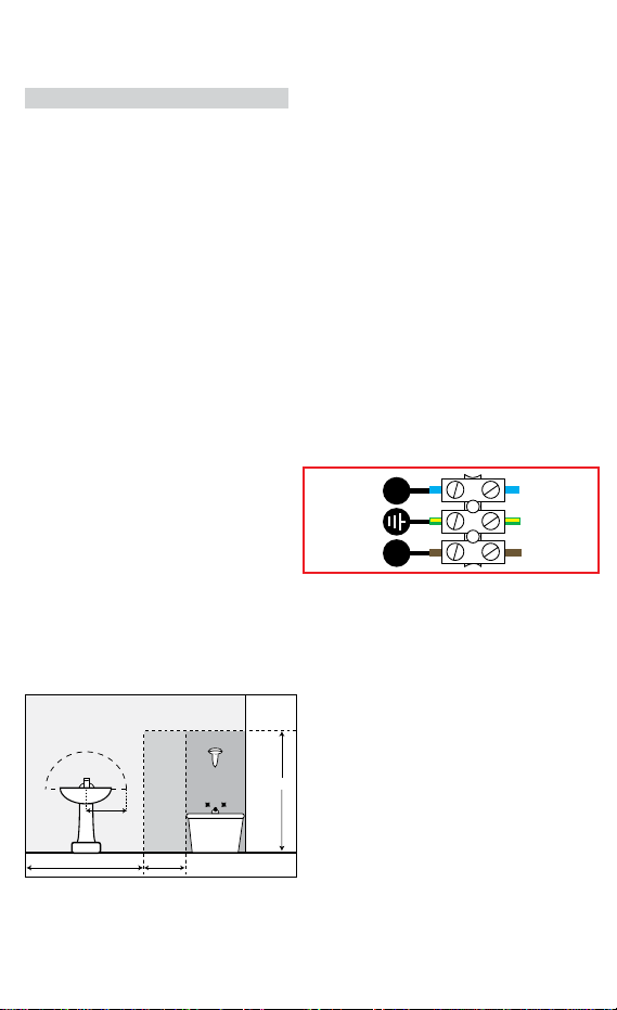
Make connections to the electrical supply in
accordance with the following code:
Live - Brown or Red
Neutral - Blue or Black
Earth - Green and Yellow
This product must be connected to Earth.
When making connections, ensure that the terminals
are tightened securely and that no strands of wire
protrude. Check that the terminals are tightened
onto the bared conductors and not onto any
insulation. Wrap loose terminal blocks well with
insulating tape.
Disconnect the tting from the electrical supply
before ash or high voltage testing.
Suitable for indoor use only.
If the location of your new tting requires the
provision of a new electrical supply, the supply
must conform with the requirements of the Building
Regulations making reference to the current edition
of the IEE Wiring Regulations (BS7671).
You are advised at every stage of your installation to
double-check any electrical connections you have
made. After you have completed your installation
there are electrical tests that should be carried out:
these tests are specied in the Wiring Regulations
(BS7671) referred to in the Building Regulations.
INSTALLATION:
01. Choose the location for your mirror light
complying with the conditions listed opposite.
02. Lay the tting at and remove the four screws
that retain the mirror (two each side).
03. Lift the mirror o of the tting and store safely.
04. Using the metal case as a template, mark the
position of the xing holes. Laying a spirit level
across the top of the metal case will help ensure
that your mirror is installed level.
05. Prepare the xing holes as appropriate to your
mounting surface.
06. Pierce the rubber grommet in the cable entry
hole that you intend to use. Do not make the
hole too large, the rubber grommet must make a
watertight seal around the supply cable.
07. Thread the supply cable through the pierced
grommet.
08. Secure the metal case to the wall using the
xings supplied. If the xings supplied are not
appropriate to your installation, use suitable
alternatives.
09. Remove the plastic box covering the mains
terminals.
10. Make the electrical connections according to the
colour code opposite.
11. Re-t the plastic cover over the terminals.
12. Check that the soft gasket is correctly positioned
around the facing edge of the metal case.
13. Replace the mirror and secure in position using
the four screws removed previously. Press rmly
on the mirror to ensure a tight t against the
gasket before tightening screws.
14. Restore the power and switch on.
REPLACEMENT LAMP TYPE:
225cm
60cm240cm
60cm
radius
from tap
ZONE 1
ZONE 0
ZONE 2
ZONE 2
Bathroom Zones Diagram
The light source contained in this luminaire
shall only be replaced by the manufacturer,
service agent or a similar qualied person.
CAUTION, RISK OF ELECTRIC SHOCK.
The light source is designed to last the lifetime of the
luminaire.
NEUTRAL
(Power Cable)
EARTH
(Power Cable)
LIVE
(Power Cable)
N L
Yellow/Green
Blue
Brown
NOTE:
The shaver socket supplied with this unit is
designed for standard shaver plugs and may not be
suitable for other devices i.e. electric toothbrushes