Eterra MIX-N-GO BMX-100 User manual

Identifier:
MIX-N-GO
Revision:
5.2
Effective Date:
1/27/20
Document Catalog Number: ET-BMX-100/250/450/600
Author: Robert Leib
MIX-N-GO BMX-100/250/450/600
Eterra, LLC.
A Skid Steer Solutions, Inc. Company
Bellingham, Washington
USA
www.eterra-usa.com
User Manual
For information and customer support – speak with your
dealer or visit our website www.eterra-usa.com

MIX-N-GO - User Manual Rev 5.2
Page 2 of 41
Copyright © 2020 [Skid Steer Solutions, INC. & Eterra LLC.].
All rights reserved.
No part of this publication may be reproduced, transmitted, transcribed,
stored in a retrieval system, or translated into any language, in any form or
by any means, electronic, mechanical, photocopying, recording, or
otherwise, without prior written permission from [Eterra, LLC.].
All copyright, confidential information, patents, design rights and all other
intellectual property rights of whatsoever nature contained herein are and
shall remain the sole and exclusive property of Eterra, LLC. The information
furnished herein is believed to be accurate and reliable.
However, Eterra, LLC. assumes no responsibility for its use, or for any
infringements of patents or other rights of third parties resulting from its use.
The Eterra & Eterra name and logo are trademarks or registered
trademarks of Eterra, LLC.
All other trademarks are the property of their respective owners.

MIX-N-GO - User Manual Rev 5.2
Page 3 of 41
Table of Contents
About This Manual ........................................................................................................................................4
1. Introduction............................................................................................................................................5
1.1. Purpose...........................................................................................................................................................5
1.2. Scope ................................................................................................................................................................5
1.3. Safety Marking..............................................................................................................................................6
1.4. General Safety............................................................................................................................................... 6
1.5. Operational Safety ......................................................................................................................................7
1.6. Maintenance & Transport Safety...........................................................................................................8
2. Operation.................................................................................................................................................9
2.1. Introduction ..................................................................................................................................................9
2.2. Theory of Operation................................................................................................................................ 10
2.3. Bucket Delivery And Acceptance........................................................................................................ 11
2.1. Main Operational Components............................................................................................................ 12
2.1. Main Components BMX-100 ................................................................................................................. 14
2.2. Main Components BMX-250/450/600 ............................................................................................. 15
2.3. Safety Devices – BMX-250/450/600.................................................................................................. 16
2.4. Maximum Bucket Loading..................................................................................................................... 16
2.5. Pre-Operation Checklist......................................................................................................................... 17
2.6. Hydraulic Connections ........................................................................................................................... 18
2.7. Hose Routing.............................................................................................................................................. 19
2.8. MIX&GO Operation - Initial................................................................................................................... 19
2.9. Loading the Bucket - Manually ............................................................................................................ 20
2.11. Unloading the Bucket.............................................................................................................................. 21
3. Maintenance & Trouble Shooting................................................................................................. 25
3.1. Scheduled Maintenance Table............................................................................................................. 25
3.2. MIX&GO Grease Points ........................................................................................................................... 27
3.3. Greasing the Chain Drive ....................................................................................................................... 28
3.4. Trouble Shooting...................................................................................................................................... 29
3.1. Parts List – 250 & 450 Series................................................................................................................ 30
3.1. Parts List – 600 Series............................................................................................................................. 35
3.1. Parts List – 100 Series............................................................................................................................. 40
4. Warranty............................................................................................................................................... 41

MIX-N-GO - User Manual Rev 5.2
Page 4 of 41
About This Manual
This document is divided into the following chapters:
•Chapter 1, “Introduction” – Use this to familiarize your self with the features and
safety requirements when using this product.
•Chapter 2, “Operation” - Learn how to operate this Cement Mixer efficiently and
safely.
•Chapter 3, “Maintenance and Troubleshooting Guidelines”, explains how to work the
Cement Mixer in the safest manner possible.
•Chapter 4, “Warranty” – See what you are covered for and how long. We offer one of
the most extensive and hassle free warranties in the business. We know that you
depend on this product to make a living and it shows with how easy it is to get
replacement parts and technical advice.
Who Should Use It
This guide is intended for users of different degrees of knowledge and experience with
equipment.
•Users: This manual provides all of the safety information you will need to operate the
Eterra BMX-100 & BMX-250/450 without incident.
•Technicians: All service information and parts diagrams are furnished so that you can
inspect and repair your MIX&GO yourself or with the help of a qualified service
technician.
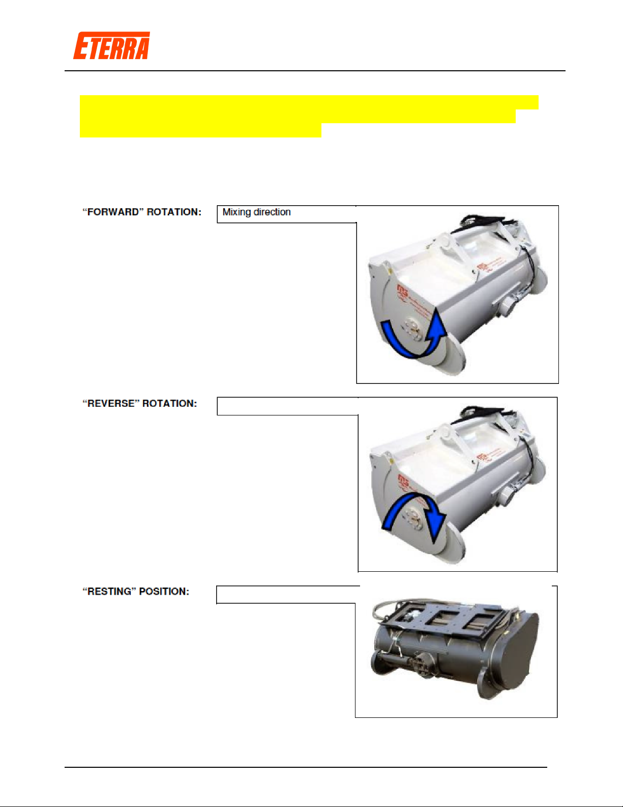
Orientation Conventions
Forward Rotation – Clockwise - Mixing Backward Rotation –Counter Clockwise Detached Position

MIX-N-GO - User Manual Rev 5.2
Page 5 of 41
1. Introduction
1.1. Purpose
The Eterra BMX-100 & BMX-250/450/600 Cement Mixers are designed to be used with
skid steer loaders or excavators of the appropriate weight class. They are intended to be
used by operators of all experience levels. To accomplish this feat, a very simple design
has been used which is unlike anything else found in the industry. By offering a manual
side chute and hydraulic center chute the BMX Series Cement Mixers are the most
versatile cement mixers found anywhere. The safety and construction features of the
BMX Cement Mixers are second to none.
You must read and understand the theory of operation so that you can operate these
Cement Mixers safely and so you can maintain the safety of the operators and
bystanders.
This product was designed to be sold online and out of the box ready to operate with the
minimal amount of assembly.
This Document:
The sole purpose of this manual is to help you train yourself to be a responsible operator
and troubleshooter of the operation of the Eterra MIX&GO so that you can identify safety
issues before anything serious can happen. Failure to follow the directives noted in this
document may lead to serious injury or death.
1.2. Scope
Please read and understand all safety directives prior to operation and follow the initial
start-up procedure before ever powering up the MIX&GO. It is extremely important
that the MIX&GO is checked and re-checked prior to each operation and that it is
thoroughly cleaned after each use to minimize damage caused by seized parts.

MIX-N-GO - User Manual Rev 5.2
Page 6 of 41
1.3. Safety Marking
Safety Alert Symbols are used throughout this manual and on decals on your Cement
Mixer. When you see symbols become alert to safety information and adhere to it to
prevent injury or death.
SIGNAL WORDS - There are signal words that are used in conjunction with the safety
alert symbol; these signal words have been selected using the following guidelines:
DANGER – An immediate and specific hazard WILL result in severe personal injury or
death if the proper precautions are not taken.
WARNING – A specific hazard or unsafe practice that could result in severe personal
injury or death if proper precautions are not taken.
CAUTION – Unsafe practices which could result in personal injury if proper practices are
not taken, or as a reminder of good safety practices.
You, as the owner of an Eterra Cement Mixer are responsible for its safe operation and
maintenance. You need to make sure anyone working with, maintaining or working
around the Cement Mixer is familiar with the operation and maintenance of the unit. Be
alert, know all safety information in this manual and adhere to safety practices at all
times.
Remember a safe operator is the key to avoiding most accidents. Most accidents can be
avoided by – THINKING SAFETY AND WORKING SAFELY.
1.4. General Safety
•Read, study and understand your Operator’s Manual.
•Understand all safety symbols before operating or maintaining the MIX&GO.
•After maintaining or adjusting, make sure all tools and foreign objects are removed.
•Stop Skid Steer, set park brake and remove the key from ignition. Make sure all
moving parts have been stopped before dismounting your Skid Steer for any reason.
•Make sure all guards and shields are properly installed and secure.
•NEVER leave the Cement Mixer lifted off the ground and stand under it for any
reason.

MIX-N-GO - User Manual Rev 5.2
Page 7 of 41
1.5. Operational Safety
•Read and understand the Operator’s Manual and all safety signs before operating,
servicing, adjusting or unplugging.
•Do not allow riders on the Skid Steer during field operation or transport.
•Install and secure all guards and shields before starting and operating.
•Never wear ill-fitting, baggy or frayed clothing when working around or on any of the
drive system components.
•Keep hands, feet, hair and clothing away from all moving and/or rotating parts.
•Never operate the machine inside a closed building.
•Stop Skid Steer engine, place hydraulic controls in neutral, set park brake, remove
ignition key and wait for all moving parts to stop before servicing, adjusting, repairing
or unplugging.
•NEVER EVER Climb out of your machine with the boom raised. Serious injury or
death can occur.
•Ensure that all Skid Steer controls are in neutral before starting.
•Clear the area of all bystanders, especially children, before starting.
•Be careful when working around or maintaining a high-pressure hydraulic system.
Wear proper eye and hand protection when searching for a high-pressure leak. Use a
piece of wood or cardboard as a backstop when searching for a pin-hole leak in a
hose or line.
•Before applying pressure to the hydraulic system, make sure all components are tight
and that steel lines, hoses and couplings are not damaged.
•Take care when working on steep ground, particularly when turning, and especially
with mounted Cement Mixers.
•Stay away from overhead obstructions and power lines during set-up and operation.
Electrocution can occur without direct contact.
•Review all safety instructions annually.

MIX-N-GO - User Manual Rev 5.2
Page 8 of 41
1.6. Maintenance & Transport Safety
•Review the Operator’s Manual and all related Maintenance, Operating and SAFETY
information annually with all personnel who will be working with, maintaining or
operating the Cement Mixer.
•Be careful when working around or maintaining high-pressure hydraulic systems.
Wear proper eye and hand protection when searching for a high-pressure hydraulic
leak. Use a piece of wood or cardboard as a backstop when searching for a pin-hole
leak in a hose or steel line. Do not attempt any makeshift repairs to the hydraulic
lines, fittings or hoses by using tape, clamps or cements. The hydraulic system
operates under extremely high-pressure. Such repairs will fail suddenly and create a
hazardous and unsafe condition.
•Before applying pressure to a hydraulic system, make sure all components are tight
and that steel lines, hoses and couplings are not damaged.
•Seek immediate medical attention if a high-pressure concentrated stream of hydraulic
fluid pierces the skin, as a toxic reaction and infection could develop.
•Keep hands, feet, clothing and hair away from all moving and/or rotating parts.
•Never wear ill-fitting, baggy or frayed clothing when working around or on any of the
drive system components.
•Clear the area of all bystanders, especially children, when carrying out any
maintenance or making adjustments on the systems components.
•Lower boom to the ground before servicing, adjusting or repairing the machine.
•When moving on or near roadways, make sure the SMV (Slow Moving Vehicle)
emblem and all the lights and reflectors that are required by the local highway and
transport authorities are in place, are clean and can be seen clearly by all overtaking
and oncoming traffic.
•Never transport with the boom arms extended upward. Boom arms should be in the
stowed position in towards the Skid Steer when transporting.
•Do not allow riders on any parts of the machine during either field operation or road
and highway travel.
•Attach the Cement Mixer to the Skid Steer using the skid mounting plate. Always use
warning flashers (hazard) on the Skid Steer when transporting unless prohibited by
law.
MIX-N-GO - User Manual Rev 5.2
Page 9 of 41
2. Operation
2.1. Introduction
The Skid Steer BMX Cement Mixers were designed to be a highly effective mixing
solution. If maintained properly, it will provide the owner with many years of service with
no damage to property or people. If not maintained properly, the MIX&GO can easily
injure people or property and will not last as long as the design allows. You must visually
inspect and test the MIX&GO before and after each use to insure nothing has come loose
or is badly worn. The Owner’s Manual is designed to help you be a safe and
knowledgeable operator of this Cement Mixer.
Please follow the machine-sizing chart below to ensure you do not cause an unbalanced
situation with your loader when the bucket is loaded.
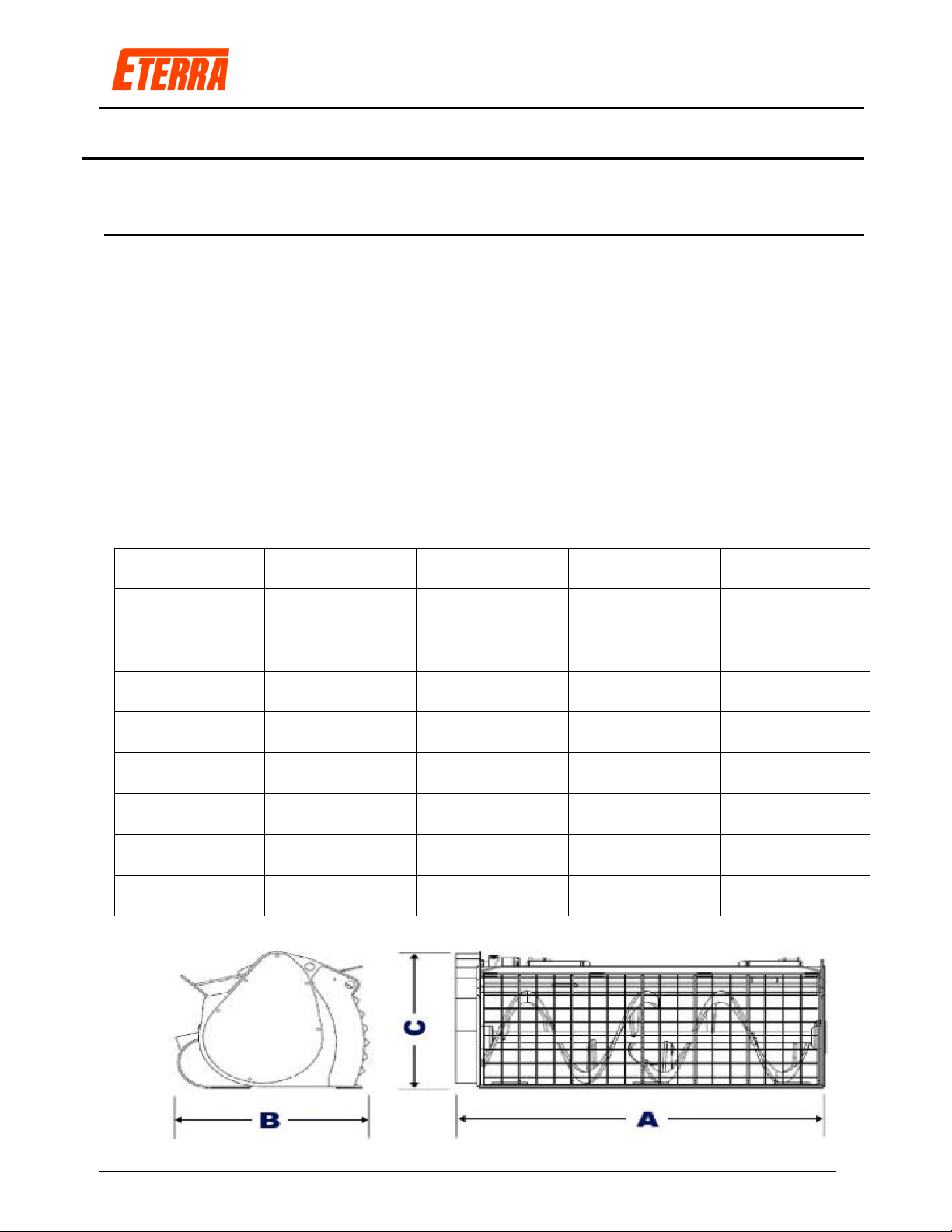
MODEL BMX-100 BMX-250 BMX-450 BMX-600
Weight - Empty 529 lbs. 870 lbs. 947 lbs. 1488 lbs.
Weight - Full 1007 lbs. 2083 lbs. 2888 lbs. 4246 lbs.
Max Flow 15 GPM 21 GPM 21 GPM 21 GPM
Max Pressure 3000 PSI 3500 PSI 3500 PSI 3500 PSI
Dimension A 1260mm/49.5” 1480mm/58.25” 1630mm/64.25” 1900mm/75”
Dimension B 760mm/30” 784mm/31” 890mm/35” 1120mm/44”
Dimension C 580mm/22.75” 696mm/27.5” 810mm/32” 1000mm/39”

MIX-N-GO - User Manual Rev 5.2
Page 10 of 41
2.2. Theory of Operation
The MIX&GO BMX-250/450/600 is a twin door concrete mixing bucket has been
designed to prepare concrete, mortar, cement or semi-dry concrete mix. The bucket has
been especially designed to be fitted to skid steer loaders and excavators of the
appropriate weight rating. The MIX&GO BMX-100 is a single door mixing bucket
designed specifically for mini skid steer loaders. To save weight and size, not all features
available on the BMX-250/450 are available on the BMX-100.
The mixing shaft rotates around its axis generating a convective movement of the
material, which is therefore perfectly mixed due to the special design of the auger flights.
Connected through a chain drive, an orbital hydraulic motor transfers motion to the shaft.
The material is constantly pushed toward the left side where it can be discharged through
the hydraulically-operated discharge hole at the back of the bucket, or through the lateral
discharge hole with manual opening. The mixer comes standard with a welded coupling
frame specially designed for skid steer loaders and bracket mounting holes for excavator
mounting. Hydraulic power is supplied by the machine’s hydraulic circuit. Connections
are made through hydraulic quick connectors. All bucket’s functions are controlled by
means of the controls available on the machine. An additional electric solenoid is
provided on the BMX-250/450/600 for control of the center chute. See images below for
mixing direction and resting position.
Since the release of the BMX mixers in 2012, customers have reported using them for the
following projects.
•Mixing old paint into a solid using a special mix that hardens the paint.
•Stray/Mud houses. Mixing mud with stray to build a stray house.
•Adobe clay mixing.
The following activities are strictly forbidden:
•Mixing of Asphalt.
•Mixing of material with a diameter greater than 1.25”.
•Any kind of grinding activity whatsoever.
•Digging, towing, pulling or tearing using the bucket.
•Never put hands inside the bucket or slide tools into bucket while operational.
•Removal of protection grill while operational.
MIX-N-GO - User Manual Rev 5.2
Page 11 of 41
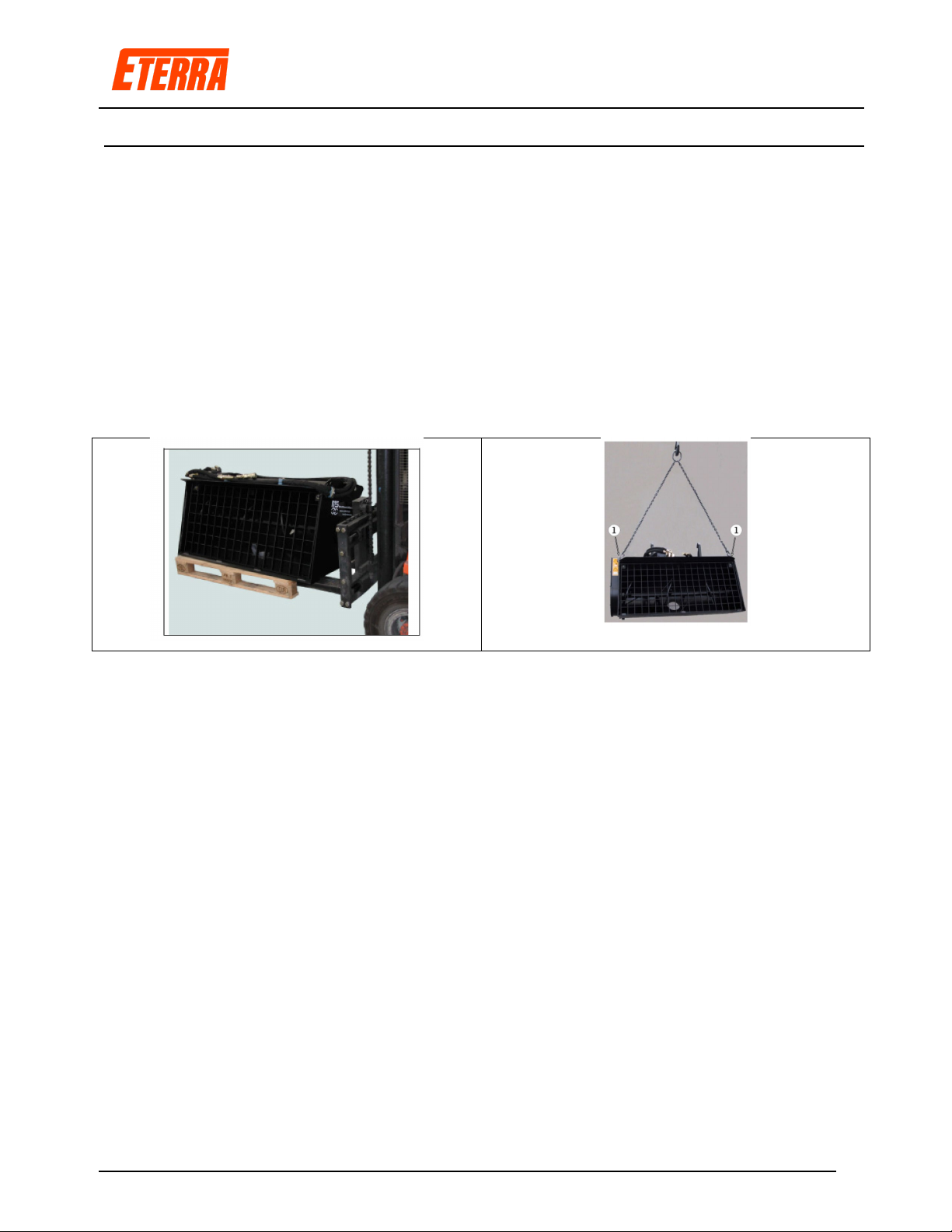
2.3. Bucket Delivery And Acceptance
The buckets are normally banded and wrapped on a pallet. They are wrapped in plastic,
cardboard and then more plastic to ensure they are delivered in perfect condition. All
shipments are photographed prior to and after wrapping just before shipping. Upon receipt,
check the bucket for shipping damage and record any issues on the Waybill prior to
releasing the delivery truck. No claims can be made after the driver leaves.
Handle the bucket when delivered on a pallet with pallet forks. Once the packing material
has been removed, you can install the bucket onto your loader.
Additionally you can move the bucket using the supplied carrying loops with the proper
chain hooks in place.
MIX-N-GO - User Manual Rev 5.2
Page 12 of 41
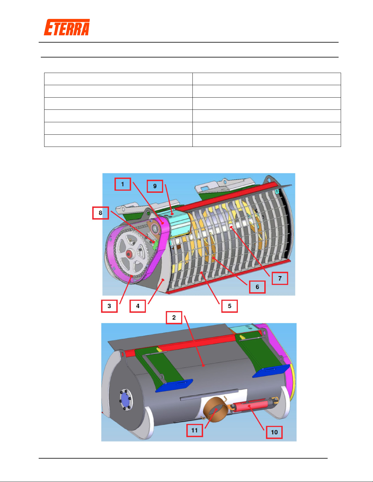
2.1. Main Operational Components
1 – Chain Case
7 – Auger Shaft
2 – Main Machine Coupling
8 – Chain Tensioner
3 – Drive Chain
9 - Motor
4 – Bucket Body
10 – Hydraulic Chute Actuator
5 – Protection Grill
11 – Bottom Hydraulic Chute
6 – Mixing Auger
12 – Side Chute on Some Models
MIX-N-GO - User Manual Rev 5.2
Page 13 of 41
Important: The standard operational direction is forward. It is all right to reverse the
bucket momentarily, but for the best mixing conditions and longevity of the chain
tensioner, the forward direction is preferable.
MIX-N-GO - User Manual Rev 5.2
Page 14 of 41
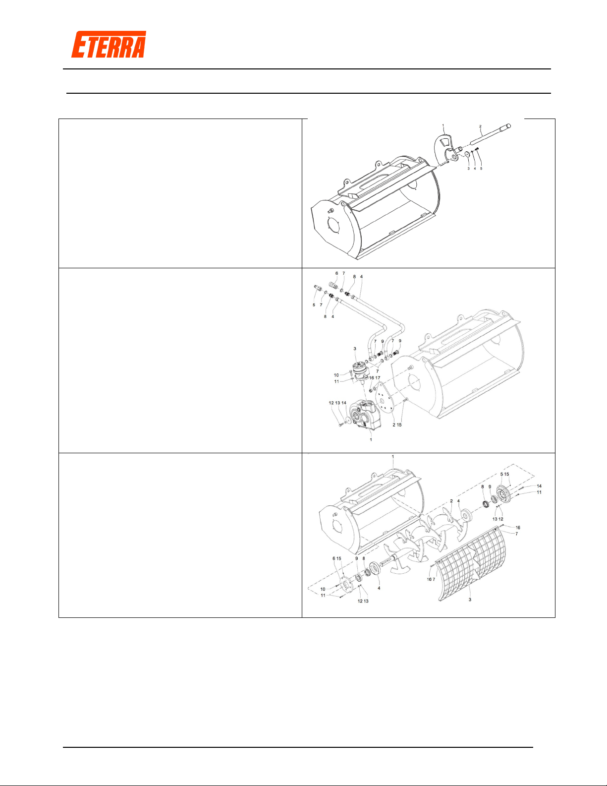
2.1. Main Components BMX-100
1: Side Door
2: Lever
3: Shaft Retainer
4: Washer
5: Screw
1: Reduction Gear
2: Casing Cover
3: Reduction Gear Mounting Plate
4: Feed Pipe
5: Female Quick Connect
6: Male Quick Connect
7: Bonded Washer
8: Pipe Nipple
9: Drilled Bolt
10: Screw
11: Washer
12: Screw
13: Washer
14: Shaft Reatainer
15: Screw
16: Nut
17: Washer
1: Bucket Body
2: Mixing Shaft
3Protective Grid Cover
4: Seal Housing Flange
5: Non-Drive Side Flange
6: Drive Side Flange
7: Nut
8: Dust Seal
9: Roller Bearing
10: Screw
11: Screw
12: Washer
13: Nut
14: Screw
15: Greasing Nipple (Zerk)
16: Screw

MIX-N-GO - User Manual Rev 5.2
Page 15 of 41
2.2. Main Components BMX-250/450/600
1)
Drive guard
2) Attachment coupling frame for skid steer loader
3) Drive chain
4) Bucket body
5) Front grid
6) Mixing auger
7) Auger shaft
8) Chain tensioner
9) Motor guard
10) Discharge hole jack guard
11) Discharge hole opening jack
12) Rear discharge hole
13) Hydraulic motor
14) Lateral discharge hole
15) Lateral discharge hole operating lever
MIX-N-GO - User Manual Rev 5.2
Page 16 of 41
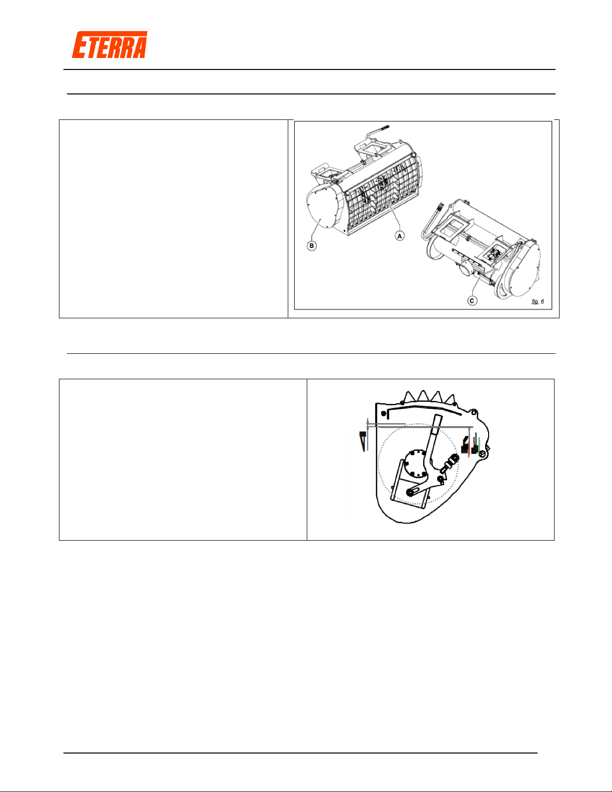
2.3. Safety Devices – BMX-250/450/600
The mixer comes complete with a front
grill (Fig A), bolted to the frame, which
prevents any contact with the mixing
shaft. The drive system, guard (Fig B),
bolted to the frame, covers the chain and
gears. The handle operating the opening
of the discharge hole is protected by the
guard (Fig C).
2.4. Maximum Bucket Loading
Visually, it is possible to load the equipment
leaving at least 2” of the external paddles
uncovered.
MIX-N-GO - User Manual Rev 5.2
Page 17 of 41
2.5. Pre-Operation Checklist
•The Eterra Cement Mixer is designed to ensure years of trouble free use. A poorly
maintained machine is an invitation to expenses and trouble. We recommend that
before operation that this checklist be followed to ensure trouble free operation.
•Give the machine a “once-over” for any loose bolts, worn parts, cracked welds,
hydraulic leaks, frayed hoses etc. and make necessary repairs. Double check the
Cement Mixer coupler as well as mounts to insure nothing has come loose as you
risk the Cement Mixer head falling off if not properly inspected.
•Check for excessive wear as well as cracks in the mixing auger. Replace as
needed.
•Be sure that there are no tools lying on or in the machine.
•Lubricate the main bearings daily or after each 8 hours of use.
•Clear any dried cement or gravel prior to each use or severe auger damage may
occur.
•Make sure all hoses are clear of cuts, abrasions, worn spots and pinch points
before operating. Check that hoses do not get caught in the pinch areas of your
skid steer boom.
•Check the tire pressure and make sure they are inflated to their recommended
pressures. Connect to Skid Steer and check mechanical Skid Steer connection
point for wear that could cause MIX&GO to fall off. Repair any damage as needed.
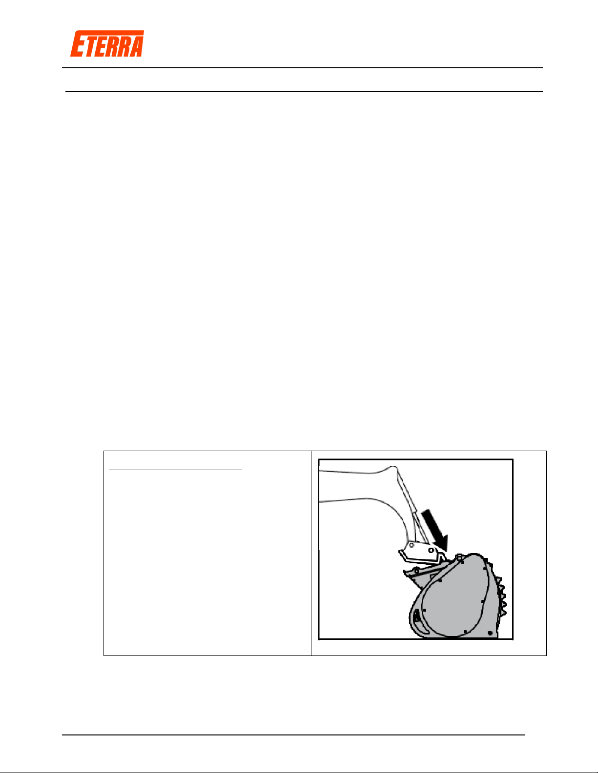
Connection to Skid Steer:
Slowly approach the machine to the
coupling plate of the equipment. Hook
the top of the machine coupling to the
top of the coupling plate. Slowly move
the machine forward and at the same
time pull the coupling back to fix the
bottom of the coupling plate (fig. 14).
Stop the machine and remove the
ignition key. Lock the coupling
between the machine and the
equipment by means of the locking
device.
•Connect hydraulic lines to skid steer and if equipped, electrical solenoid wire
connection.
MIX-N-GO - User Manual Rev 5.2
Page 18 of 41
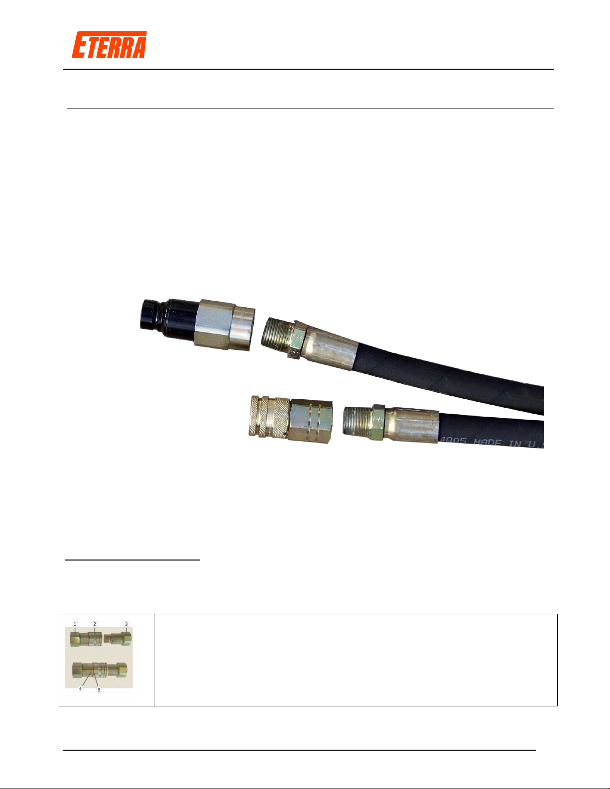
2.6. Hydraulic Connections
Depending on your order, your MIX&GO may or may not have come with hydraulic quick
couplers. The hose ends are furnished with fittings that will screw either directly into the
back of the hydraulic couplers or a 90 degree fitting depending on your specific machine
requirements. You should check the best hose routing for your machine prior to use and
adjust accordingly. The MIX&GO operates in both directions. If your controls do not work in
the direction expected, swap the couplers as your machine may have a detent position with
a reverse flow to the way your Cement Mixer was tested and shipped. Couplers can be
alternated on hose ends easily by the operator. Angled fitting either 45 degree or 90 degree
may be used to alter the length and angle of hoses for a more optimal sweep of the hoses.
•Once the couplers are installed, you may connect them to your machine by pushing
the male coupler into the female coupler on the Skid Steer and the female coupler of
the attachment into the male coupler on the Skid Steer.
Connection to Machine:
For flat faced style connections, engage the male fitting (#3) to the female coupler (#1) on
your machine by pushing the male into the female until the snap ring engages. Rotate the
ring until it passes the small ball bearing (#2). This will insure the coupler cannot release.
For removal, rotate the locking collar until the notch lines up with the
bearing and press the collar back while holding the male fitting. The
female will eject the male from the body so be prepared.

MIX-N-GO - User Manual Rev 5.2
Page 19 of 41
2.7. Hose Routing
•It is important that you check and recheck your hose routing each time you connect the
attachment to your Skid Steer. Each machine is different so you need to make sure that you
have routed the hoses away from any potential pinch points. Check that there are no pinch
points around the main skid steer pivot. Average hose lengths are shipped at no-charge with
each Cement Mixer. Try to route the hoses towards the front bottom of the mount and away
from the back pinch zone.
•It is the customers’ responsibility to modify these hose lengths locally as required for your
specific machine. Hose lengths can be varied by using or not using a 45 or 90 degree fitting.
There is no warranty either expressed or implied with regards to hose damage due to
improper routing or length.
2.8. MIX&GO Operation - Initial
•After you have connected your hoses to your machine, you will want to start the skid steer, and
turn on your auxiliary hydraulics. Run the Cement Mixer up for just a few seconds and turn off
the skid steer. Check for leaks at all hose fittings. Tighten as needed and test again.
•Run the machine and familiarize your self with the Cement Mixer and how it handles different
types of material. Stop and check for leaks. Check the auger to insure nothing has come
loose.
•The bucket (mixing shaft rotation) can only be operated from the machine. Start the engine of
the machine and let it run at idle for a few minutes with the hydraulic circuit open so that oil can
reach the recommended temperature gradually and any air trapped in the circuit can be
expelled. Use the machine controls to operate the mixing auger. On machines equipped with
four hydraulic lines, it is possible to operate the mixing shaft rotation and to open/close the
discharge hole at the same time. On machines with two hydraulic lines it is only possible to
control the mixing shaft rotation and the discharge hole opening/closing alternately.
•Do not wear loose fitting clothing or jewelry. Hearing and eye protection are highly
recommended even if you are inside an enclosed cab. Wear heavy gloves whenever you are
handling the wheel.
•Before leaving the skid steer, make sure that the hydraulic power has been turned off and the
mixer has come to a complete stop. THINK before you walk anywhere near the front of the
Cement Mixer if any covers have been removed or damaged.
•If there is any kind of excess vibration, stop using the MIX&GO at once until this has been
remedied. Replace damaged parts immediately.
•To prevent tipping or control losses, reduce your speed when making turns or transitioning
onto or off of slopes.
•Cement Mixers can be extremely dangerous due to excessive weight. Always carry material in
the lowest possible position so that you minimize your tipping potential.
•Never allow children to be near or operate this equipment.

MIX-N-GO - User Manual Rev 5.2
Page 20 of 41
2.9. Loading the Bucket - Manually
Move the bucket near the material to be loaded. Rest the bottom edge of the bucket on the ground and
parallel to it. Slowly move forward with the machine and load the material. Once the material has been
loaded, move the bucket backward and slightly raise it off the ground. Move the material by rotating the
mixing auger some turns “FORWARD”. Slowly go to the site where you wish to prepare the mix being
careful to keep the bucket as close as possible to the ground. Once the mixing site has been reached,
start the mixing auger rotation and proceed as explained in next paragraph.
Operator on the Ground: Pour the proper amount
of cement into the bucket. Pour the proper amount
of water based on the consistency of the mix you
wish to obtain. Pour water gradually into the
bucket.
Machine operator: Gradually increase the engine
speed up to 75% of the maximum speed being
careful that the auger does not exceed 30-32
RPM.
Machine Operator: Operate the control and start rotating the auger “FORWARD” (mixing direction)
keeping the engine running at 50% of the maximum speed. Ensure the bucket is not overloaded. For
proper mixing, it is advisable to leave at least 2” of the external blades free from inert material.
Especially at the beginning of the mixing phase, the compact material could heap up and come out of
the bucket. It may also occur that the auger stops if stones get stuck between the bucket bottom and the
mixing paddles. In these cases, stop rotation and reverse the rotation direction for a few turns to level or
move the material. Reverse once again the rotation direction (“FORWARD”) and ensure that the material
is mixed freely. For some types of materials which, for their properties, shall be mixed in the “semi-dry”
state, it may be necessary to reverse the rotation direction several times by observing the above
precautions.
WARNING - Never reverse the rotation direction abruptly!
Move the hydraulic control to neutral and leave it in this position for a few seconds. This will protect the
motor from the simultaneous overpressure in both delivery and return lines and the consequent failure of
the oil seals.
WARNING Once the material (concrete) has been mixed, the operator shall move with the machine up
to the unloading site keeping the bucket a few inches off the ground to prevent dangerous oscillations.
This manual suits for next models
3
Table of contents


