ETS 4431-EV User manual

SHIELDED BAG TEST SYSTEM
Model 4431-EV (Voltage & Energy)
&
Model 4431-V (Voltage Only)
(These models replace Model 431)
Operating Manual
10/10

1
IMPORTANT
SAFETY INSTRUCTIONS
(Equipment containing HV)
The equipment described in this Manual is designed and manufactured to operate within
defined design limits. Any misuse may result in electric shock or fire. To prevent the
equipment from being damaged, the following rules should be observed for installation, use
and maintenance. Read the following safety instructions before operating the instrument.
Retain these instructions in a safe place for future reference.
POWER
POWER CORD: Use only the power cord specified for this equipment and certified for the
country of use. If the power (mains) plug is replaced, follow the wiring connections
specified for the country of use. When installing or removing the power plug hold the plug,
not the cord.
The power cord provided is equipped with a 3-prong grounded plug (a plug with a third
grounding pin). This is both a safety feature to avoid electrical shock and a requirement
for correct equipment operation. If the outlet to be used does not accommodate the 3-
prong plug, either change the outlet or use a grounding adapter.
FUSES: Replace fuses only with those having the required current rating, voltage and
specified type such as normal blow, time delay, etc. DO NOT use makeshift fuses or short
the fuse holder. This could cause a shock or fire hazard or severely damage the
instrument.
POWER LINE VOLTAGE (MAINS): If the line (mains) voltage is changed or isolated by an
autotransformer the common terminal must be connected to the ground (earth) terminal of
the power source.
OPERATION
CAUTION
Equipment designed to simulate a high voltage electrostatic discharge such as the Series
900 ESD Simulators and the Model 4046 Static Decay Meter utilize voltages up to 30kV.
The basic nature of an ESD event will result in electromagnetic radiation in addition to the
high level, short duration current pulse. Therefore, personnel with a heart pacemaker
must not operate the instrument or be in the vicinity while it is being used.
DO NOT OPERATE WITH COVERS OR PANELS REMOVED. Voltages inside the
equipment can be as high as 2kV.In addition, equipment may contain capacitors up
to 200pF charged to 1kV. Capacitors can retain a charge even if the equipment is
turned off.
DO NOT OPERATE WITH SUSPECTED EQUIPMENT FAILURES. If any odor or smoke
becomes apparent turn off the equipment and unplug it immediately. Failure to do so may
result in electrical shock, fire or permanent damage to the equipment. Contact the factory
for further instructions.

2
DO NOT OPERATE IN WET/DAMP CONDITIONS: If water or other liquid penetrates the
equipment, unplug the power cord and contact the factory for further instructions.
Continuous use in this case may result in electrical shock, fire or permanent damage to the
equipment.
DO NOT OPERATE IN HIGH HUMIDITY: Operating the equipment in high humidity
conditions will cause deteriation in performance, system failure, or present a shock or fire
hazard. Contact the factory for further instructions.
DO NOT OPERATE IN AREAS WITH HEAVY DUST: Operating the equipment in high
dust conditions will cause deteriation in performance, system failure, or present a shock or
fire hazard. Contact the factory for further instructions.
DO NOT OPERATE IN AN EXPLOSIVE ATMOSPHERE: Operating the equipment in
the presence of flammable gases or fumes constitutes a definite safety hazard. For
equipment designed to operate in such environments the proper safety devices
must be used such as dry air or inert gas purge, intrinsic safe barriers and/or
explosion-proof enclosures.
DONOT USE IN ANY MANNER NOT SPECIFIED OR APPROVED BY THE
MANUFACTURER: Unapproved use may result in damage to the equipment or
present an electrical shock or fire hazard.
MAINTENANCE and SERVICE
CLEANING:Keep surfaces clean and free from dust or other contaminants. Such
contaminants can have an adverse affect on system performance or result in
electrical shock or fire. To clean use a damp cloth. Let dry before use. Do not use
detergent, alcohol or antistatic cleaner as these products may have an adverse affect on
system performance.
SERVICE: Do not attempt to repair or service the instrument yourself unless instructed by
the factory to do so. Opening or removing the covers may expose you to high
voltages, charged capacitors, electric shock and other hazards. If service or repair
is required, contact the factory.

3
1.0 INTRODUCTION
The rapid advancement in the electronics industry during the past decade has placed
increasing importance on the understanding of electrostatics and its effect on electronic
devices and systems. Electrostatic Discharge (ESD) is a common cause of
microelectronic circuit failure. Many of these devices can be seriously damaged or
destroyed by an electrostatic discharge below 30 Volts, or as a result of an electrostatic
field of only a few hundred Volts.
The static shielding bag was developed to provide a package that would protect static
sensitive components placed inside from external ESD events. Many different bag
constructions are now available that, when properly used, provide a Faraday cage
(electrostatic field attenuation) around the objects placed inside.
The most common bags are constructed from transparent polyethylene film with a
metalized layer of mylar laminated to either the outside or the inside of the bag. The
metalized side is either on the outside (metal out) or buried between the mylar and the
polyethylene film (metal in or buried metal layer). The metalized layer that provides the
shield is usually aluminum or nickel with a thickness limited to approximately 100
Angstroms to maintain bag transparency. Other constructions are available, however,
that consist of carbon grids or conductive fibers such as carbon or copper. Static
shielding is also provided by nontransparent bags that are either carbon loaded
polyethylene or foil laminated such as the MIL PRF 81705D Type I water vapor-proof
shielded bag.
In selecting the correct bag for a given application, consideration must be given to
whether the product being sensitive. The ability of the bag not to charge the object
inside and the ability of the bag to dissipate any charge on its surface in a timely
manner when grounded must also be taken into account.
Various commercial and military specifications and test standards now exist for
evaluating the different electrical and physical characteristics of the bag and/or its
material. The static dissipative characteristics of the bag material is determined by
measuring the surface resistance is accordance with Electrostatic Discharge
Association test standard ANSI/ESD STM11.11. The antistatic (ability to resist
tribocharging) characteristic is determined using procedures outlined in ESD ADV
11.21. The Electronics Industries Association Test Standard EIA 541-1988 "Packaging
Material Standards - For The Protection Of ESD Sensitive Items" currently references
similar test methods. However, ESD Association test standards are now specified.
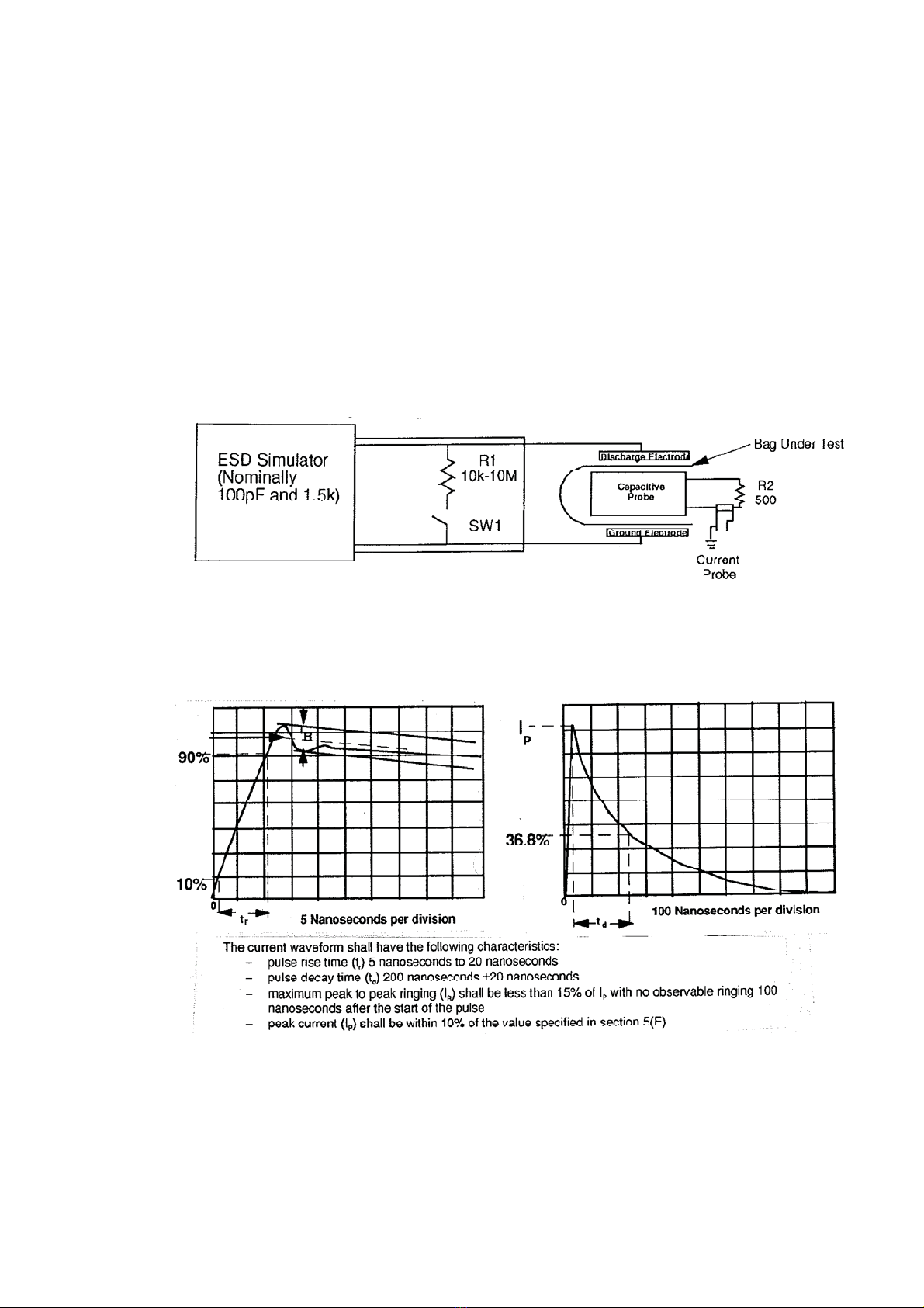
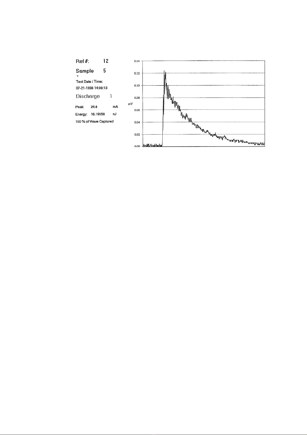
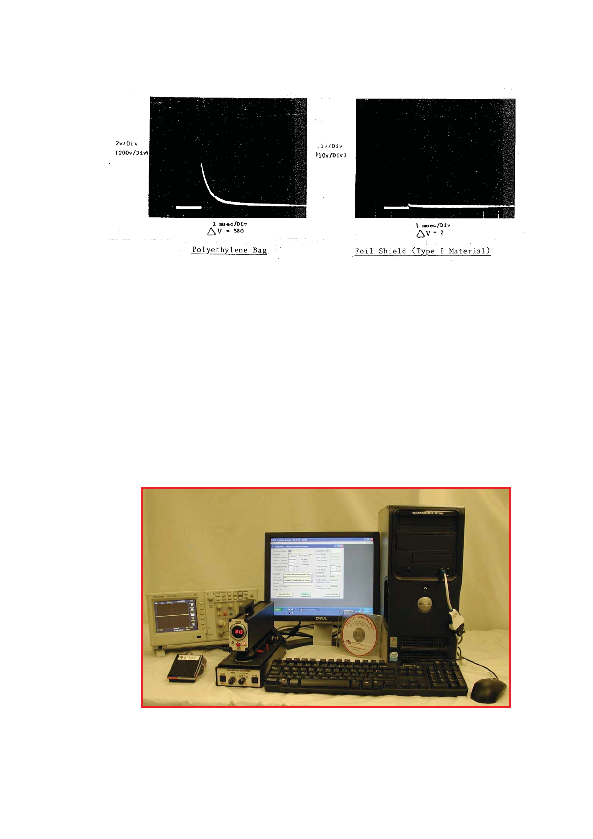
The shielding effectiveness of the bag was previously evaluated using the voltage
differential test method specified in EIA 541. However, the energy test method
specified in ANSI/ESD STM11.31 is now the preferred method. MIL PRF 81705D
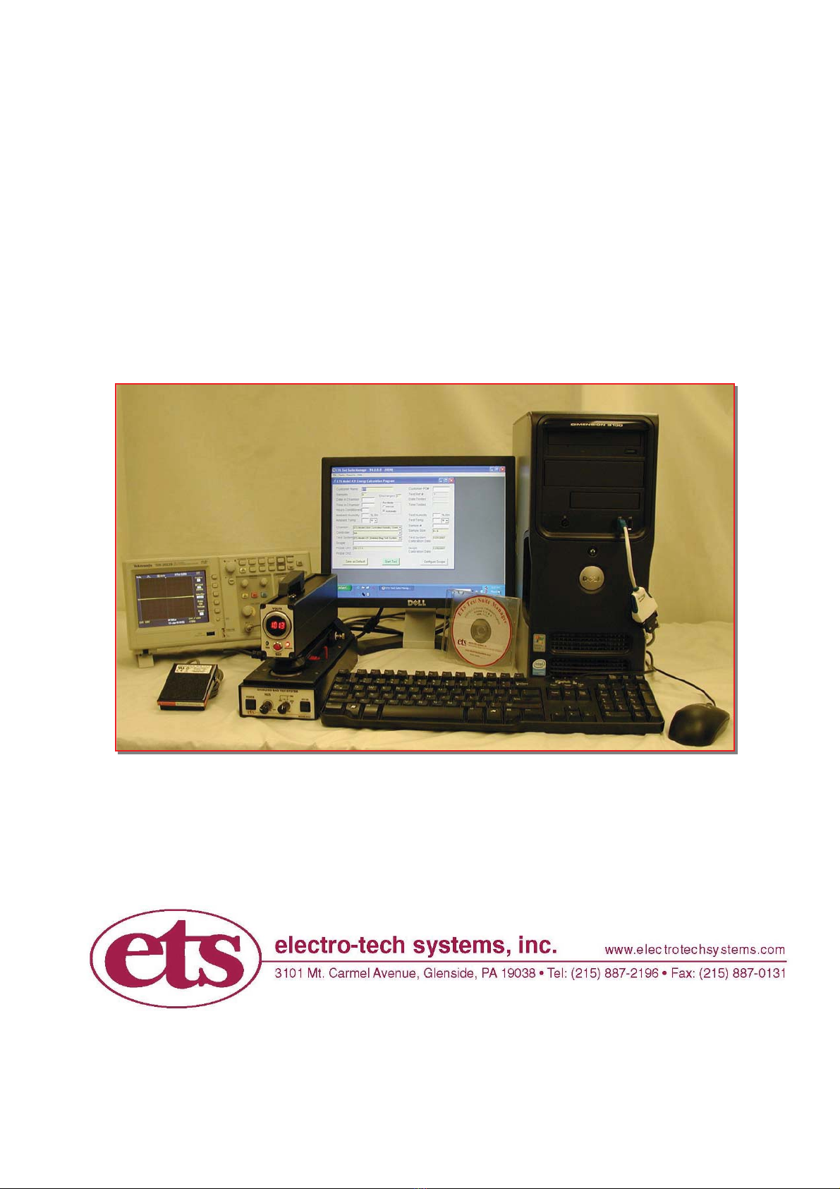
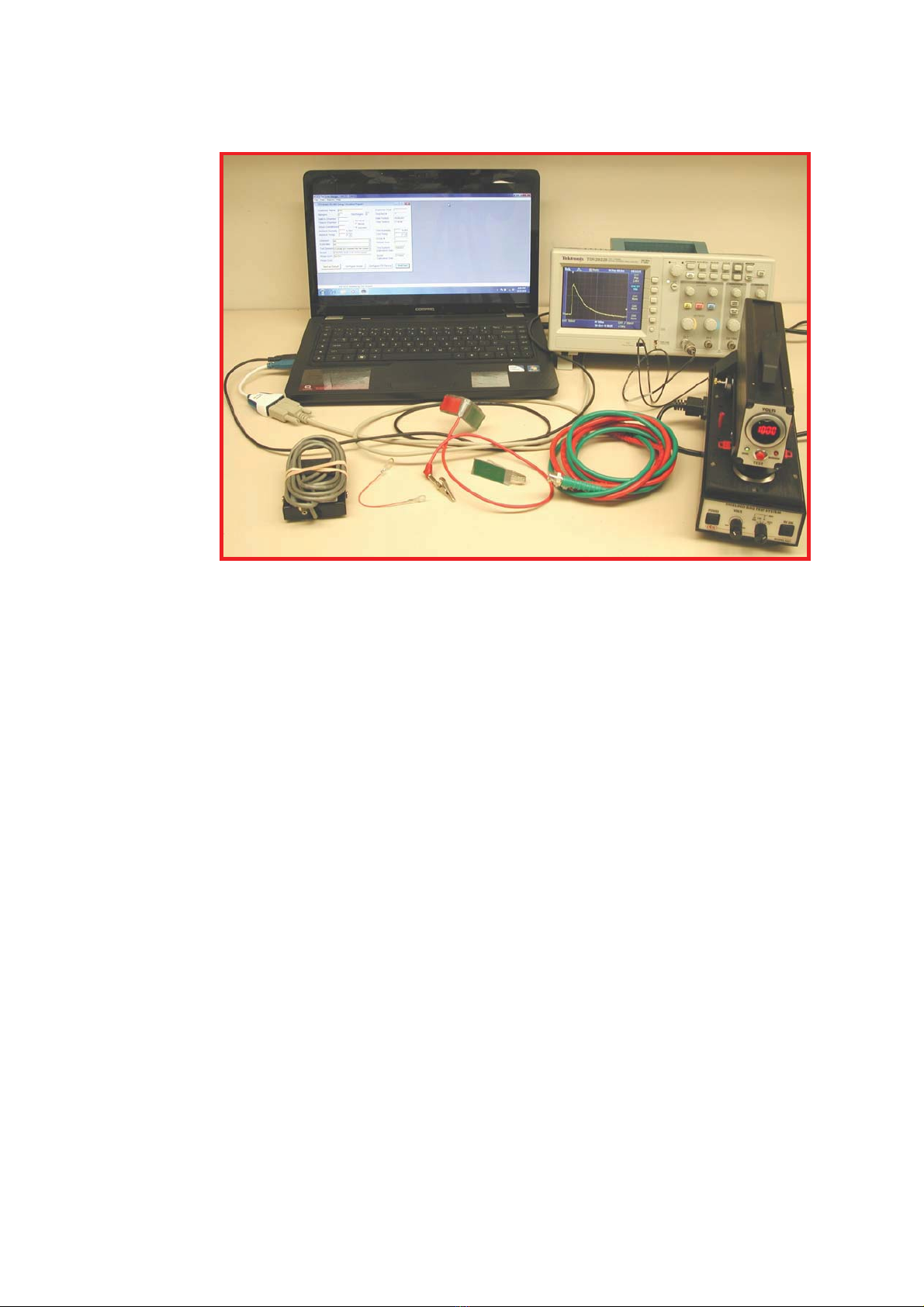
specifies the ANSI/ESD STM11.31 test. The ETS Model 4431-EV Shielded Bag Test
System meets the requirements of both test standards while the Model 4431-V
performs only the EIA 541 Voltage Differential Test. The Model 4431-EV replaces
the Model 431. Any reference in this manual that refers to the Model 431 also applies
to the Model 4431 or EV or V, unless otherwise noted.

4
2.0 TEST METHODS
2.1 ANSI/ESD STM11.31-2006 ESD Association standard for
evaluating the performance of electrostatic discharge shielding
materials - Bags
This test method evaluates the performance of electrostatic discharge shielding
bags. The purpose of this standard is to ensure that testing laboratories, using
this test method to evaluate a given packaging material, will obtain similar
results. This standard specifies the discharge waveform characteristics, probe
configuration, probe capacitance and bag size. Figure 2.0-1 shows the generic
schematic of the test system.
Figure 2.0-1: System generic schematic
Figure 2.0-2 shows the discharge current waveform requirement at the specified
1000 Volts when measured through a 500 Ohm resistor.
Figure 2.0-2: Discharge waveforms per ANSI/ESD STM5.1
The current pulse detected between the upper and lower electrodes of the
capacitive probe is used to calculate the energy inside the bag by integrating the
area under the curve as shown in Figure 2.0-3.
This manual suits for next models
1
Table of contents
Other ETS Test Equipment manuals
Popular Test Equipment manuals by other brands

Redtech
Redtech TRAILERteck T05 user manual

Venmar
Venmar AVS Constructo 1.0 HRV user guide

Test Instrument Solutions
Test Instrument Solutions SafetyPAT operating manual

Hanna Instruments
Hanna Instruments HI 38078 instruction manual

Kistler
Kistler 5495C Series instruction manual

Waygate Technologies
Waygate Technologies DM5E Basic quick start guide

StoneL
StoneL DeviceNet CK464002A manual

Seica
Seica RAPID 220 Site preparation guide

Kingfisher
Kingfisher KI7400 Series Training manual

Kurth Electronic
Kurth Electronic CCTS-03 operating manual

SMART
SMART KANAAD SBT XTREME 3G Series user manual

Agilent Technologies
Agilent Technologies BERT Serial Getting started