Instruction
Manual
For
Timegrapher
Model
P-61
2jh!
F
:.
s
:.,
S
~
~
Index
Page
1m
porta
nt
Features
-------------
------
--------
---
------
-----
---
------
--
---
-----
---
Principle
and
Construction
-------
---
---
------
---------
--------------
------------
2
How
to
Operate
---------
--
---
--
------
--
---
----------
-------
--
------------
-
-------
3
Preparation
---
----
-
--
--------
----------
-------
-------
-
---
--
---
-----------
- 3
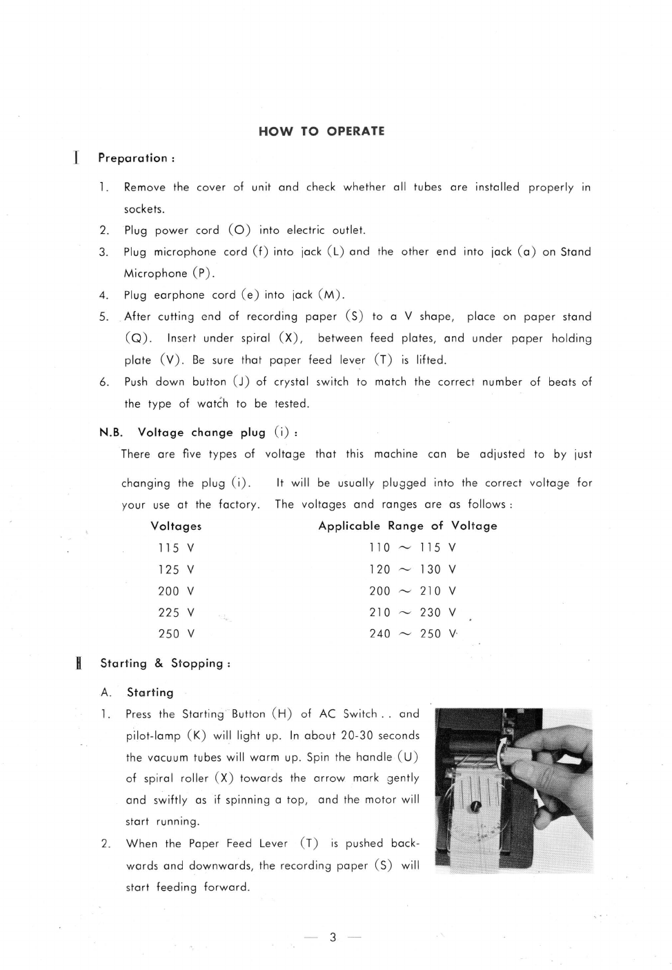
Starting
&
Stopping
-----------
-
----------------------:·------------------
3
Microphone
---
-
----------------------------------
-
----------------------
__
4
Use of
Earphone
---------------------------------------------------------
5
Ink Roller -
----
-
------------------------------
-
-----------------------------
5
Oiling
---------------------------------------------------------------------
5
Recordings
--
--
-
---
----_; _---
--------
------
---
-----
-
--------
--
---------------
---
---
6
Princi
pie
of
Recording
-----
-
-------
--
----
--
------
--
---
---
--------
--
------
6
Number
of
Beats
of
Watches
and
Clocks
-------
-
----
---------------
6
Recording
and
Volume
Adjusting---
---
----
--
-------
-
-----
--
-----
--
-----
7
Adjustment
of
Striking
Sound
-
---
--
--
--
--
--
----
---
---
-
-------
--
-
-------
7
Reading
of
Measure
Plate
and
Graph-paper
------------------------
8
Instant
Reading
by
Graph-paper-
---
--------------------
----
---
---
----
- 8
How
to
Find
Defective
Parts
in
Watches
----
--------------
-------
-
----------
9
Trouble
Shooting--_-----
_--
__
------------
---------
-----------------
----
__
---------
14
Name
of
Parts
----------------
--
--------
-
------
---------
---
----
-----
----
--
------17
Appendix
Parts
List
Circuit
Diagram