Operating Instructions
Safety Relay with IO-Link ESM-CB
2(Translation of the original operating instructions) 2522722-01-05/19
Contents
1. About this document............................................................................................. 4
1.1. Scope............................................................................................................................................4
1.2. Target group ..................................................................................................................................4
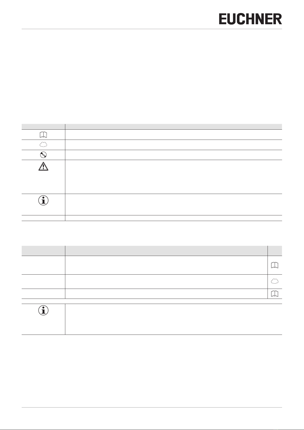
1.3. Key to symbols...............................................................................................................................4
1.4. Supplementary documents ..............................................................................................................4
2. Correct use .......................................................................................................... 5
3. Description of the safety function .......................................................................... 6
3.1. Monitoring of sensor circuits...............................................................................................6
3.2. Starting behavior ............................................................................................................................6
4. Exclusion of liability and warranty ......................................................................... 7
5. General safety precautions ................................................................................... 7
6. Function............................................................................................................... 8
6.1. IO-Link communication and functions ................................................................................................8
6.1.1. Enabling from the non-safety-related control system..............................................................8
6.1.2. Chain reset........................................................................................................................8
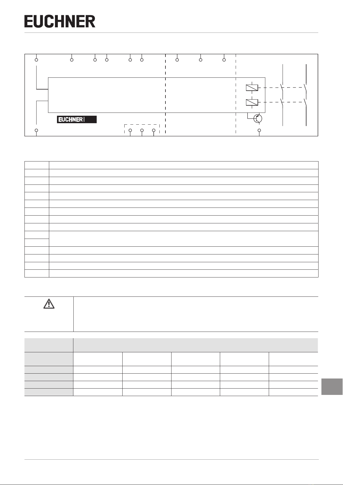
6.2. Block diagram ................................................................................................................................9
6.2.1. Insulation coordination........................................................................................................9
6.3. Communication and functions with BR safety switches.....................................................................10
6.3.1. Diagnostic data................................................................................................................10
6.3.2. Hot plugging – replacing a BR safety switch.......................................................................10
6.4. Function of monitoring output OM ..................................................................................................10
7. Mounting............................................................................................................ 11
8. Electrical connection .......................................................................................... 12
8.1. Terminal assignment .....................................................................................................................13
8.2. Signaling device connection variants ..............................................................................................14
8.2.1. Sensor circuit S1 ..................................................................................................14
8.2.2. Sensor circuit S2.............................................................................................................14
8.3. Start circuit and feedback loop connection variants.........................................................................15
8.4. Notes about ..........................................................................................................................16
9. Application example ........................................................................................... 16
9.1. Dual-channel monitoring of emergency-stop pushbutton and safety switch chain with IO-Link ...............16
10. Setup ................................................................................................................. 18
11. Calculating the power dissipation ........................................................................ 19
12. Function test ...................................................................................................... 20