manuals.online logo
Brands
  1. Home
  2. •
  3. Brands
  4. •
  5. EUCHNER
  6. •
  7. Relay
  8. •
  9. EUCHNER ESM-BT4 Series User manual

EUCHNER ESM-BT4 Series User manual

1
Operating Instructions
Safety Relay ESM-BT4..
Correct use
ESM-BT4.. is an emergency stop safety relay com-
bination that combines non-time-delayed (u) and
time-delayed (v) contacts in a very compact housing.
This permits dangerous components of a system to
be switched off quickly and safely in an emergency
situation. At the same time, other safety circuits
can continue to be supplied with power for up to
30 seconds to allow a tool to be moved to its idle
position or to brake overtraveling parts, for example.
Before the device is used, a risk assessment must
be performed on the machine, e.g. according to the
following standards:
fENISO13849-1
fENISO12100
fIEC62061.
Correct use includes observing the relevant require-
ments for installation and operation, particularly
based on the following standards:
fENISO13849-1
fEN60204-1
fIEC62061.
Important!
fThe user is responsible for the integration of
the device in a safe overall system. For this
purpose, the overall system must be validated,
e.g. according to ENISO13849-2.
fThe device user must assess and document
remaining risks.
fIf a data sheet is included with the product, the
information on the data sheet applies.
Safety precautions
WARNING
fInstallation and setup of the device must be
performed only by authorized personnel.
fObserve the country-specic regulations when
installing the device.
fThe electrical connection of the device is only
allowed to be made with the device isolated.
fThe wiring of the device must comply with the
instructions in these operating instructions,
otherwise there is a risk that the safety function
will be lost.
fIt is not allowed to open the device, tamper with
the device or bypass the safety devices.
fAll relevant safety regulations and standards are
to be observed.
fThe overall concept of the control system in
which the device is incorporated must be vali-
dated by the user.
fFailure to observe the safety regulations can re-
sult in death, severe injuries and serious damage.
fNote down the version of the device (see type la-
bel Vx.x.x) and check it each time prior to setup.
If the version changes, the use of the device in
the overall application must be validated again.
Features
f4 safe, redundant relay outputs. Depending on
variant:
- 3 non-time-delayed contacts, 1 time-delayed
contact
- 2 non-time-delayed contacts, 2 time-delayed
contacts
- 1 non-time-delayed contact, 3 time-delayed
contacts
fContinuously adjustable delay time (1 … 30 s)
or fixed delay time (ESM-BT4..-20S (2 s);
ESM-BT4..-50S (5s))
fConnection of:
- Emergency stop buttons
- Safety switches
- Non-contact safety switches
- Safety components with OSSD outputs
fSingle- and dual-channel operation possible
fFeedback loop for monitoring downstream contac-
tors or expansion modules
fCyclical monitoring of the output contacts
fIndication of the switching state via LED
f2 starting behaviors possible:
- Monitored manual start
- Automatic start
fShort circuit and ground fault monitoring
fUse up to PLe, SILCL3, category4
Function
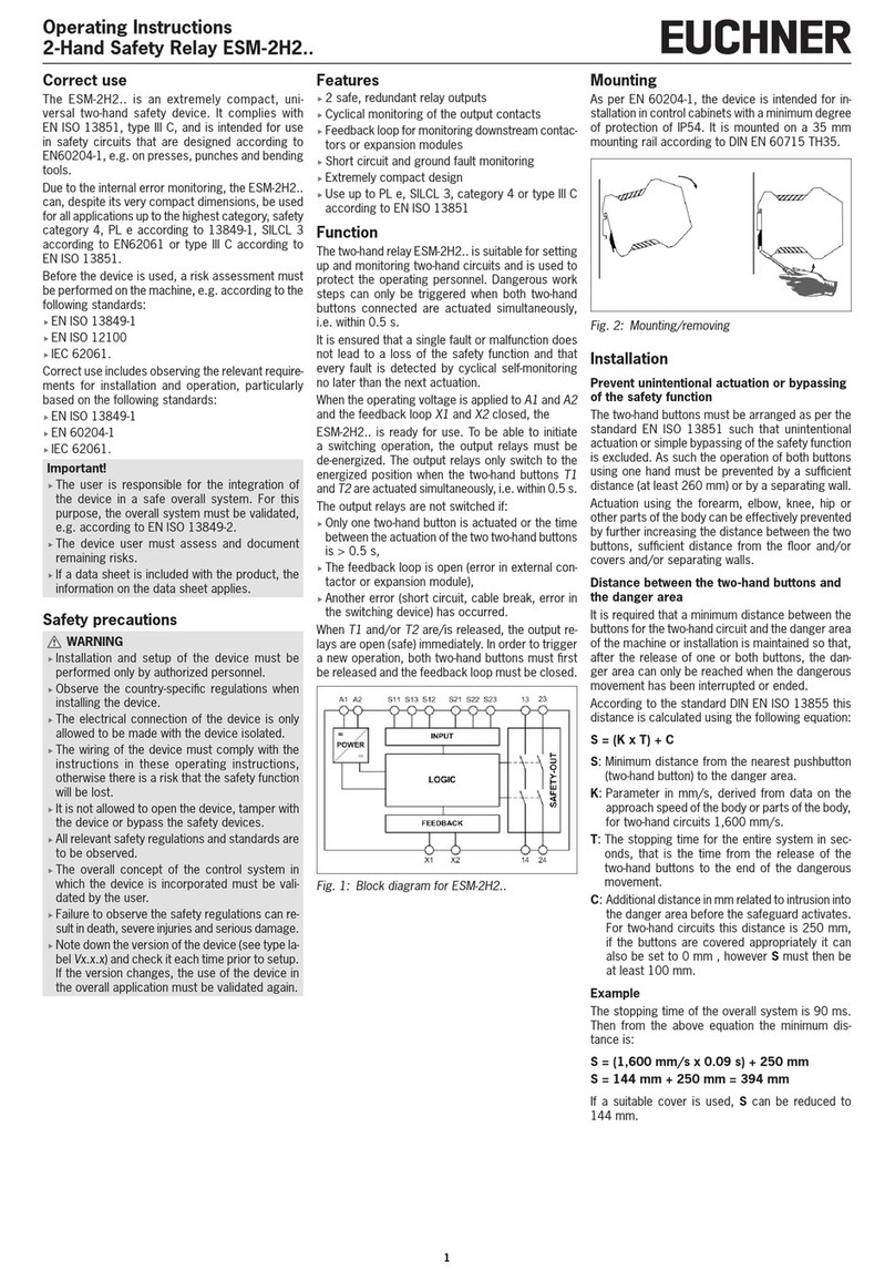
The moving parts of a machine or system can be
quickly and safely stopped in case of danger with the
non-time-delayed contacts of the ESM-BT4... Safety
contacts with time-delay switch-off are also integrat-
ed into the ESM-BT4... They are used whenever it is
safer to keep supplying power to parts of a machine
after the emergency stop button is actuated.
It is ensured that a single fault or malfunction does
not lead to a loss of the safety function and that
every fault is detected by cyclical self-monitoring
no later than when the system is switched off and
switched on again.
The time-delayed contacts switch on at the same
time as the non-time-delayed contacts, but they are
switched off again only after the time set on the
potentiometer elapses (1…30s) or after a xed
delay time (ESM-BT4..-20S; ESM-BT4..-50S) when
the emergency stop button is operated.
The power supply must be present during the time
sequence.
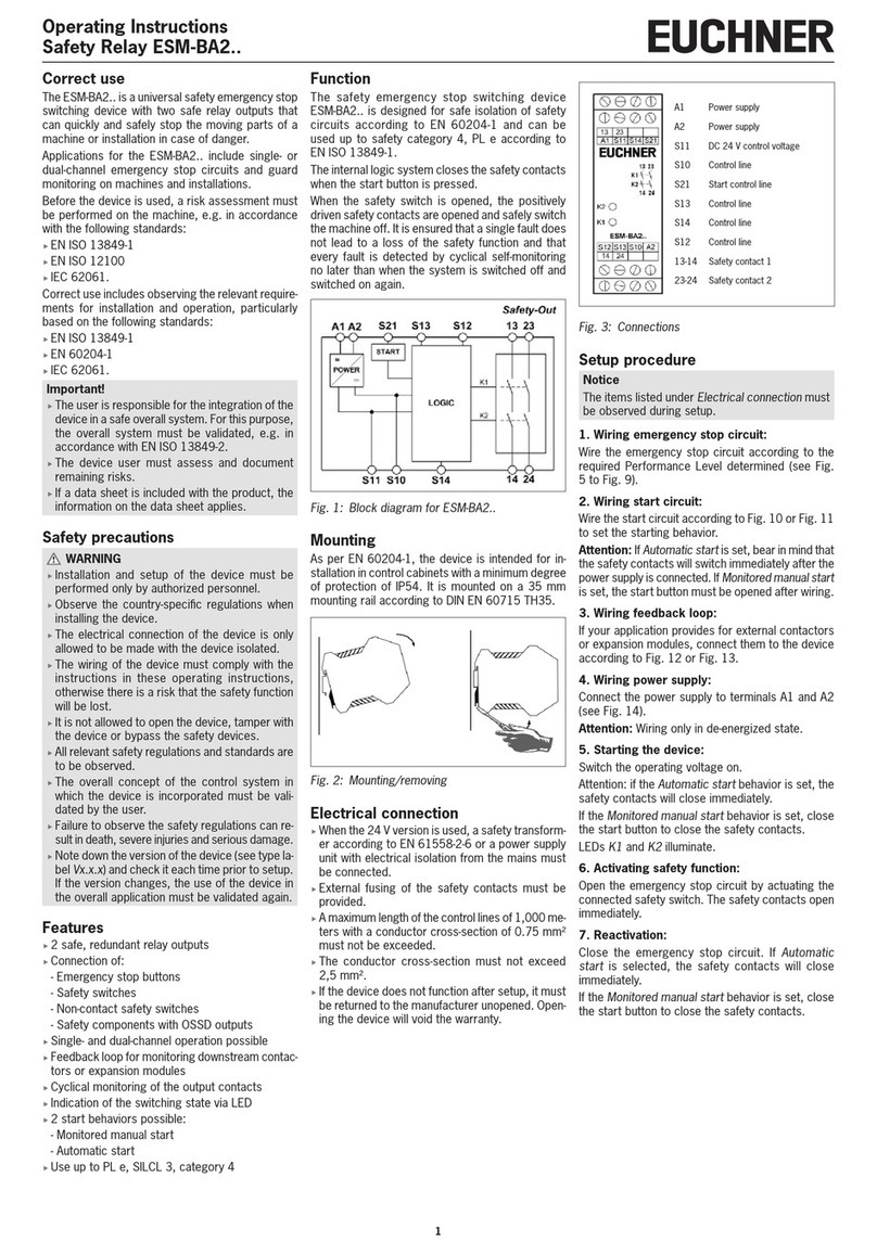
ESM-BT401 (1 non-time-delayed/3 time-delayed)
ESM-BT411 (2 non-time-delayed/2 time-delayed);
ESM-BT421 (3 non-time-delayed/1 time-delayed)
Fig. 1: Block diagrams ESM-BT4..
Mounting
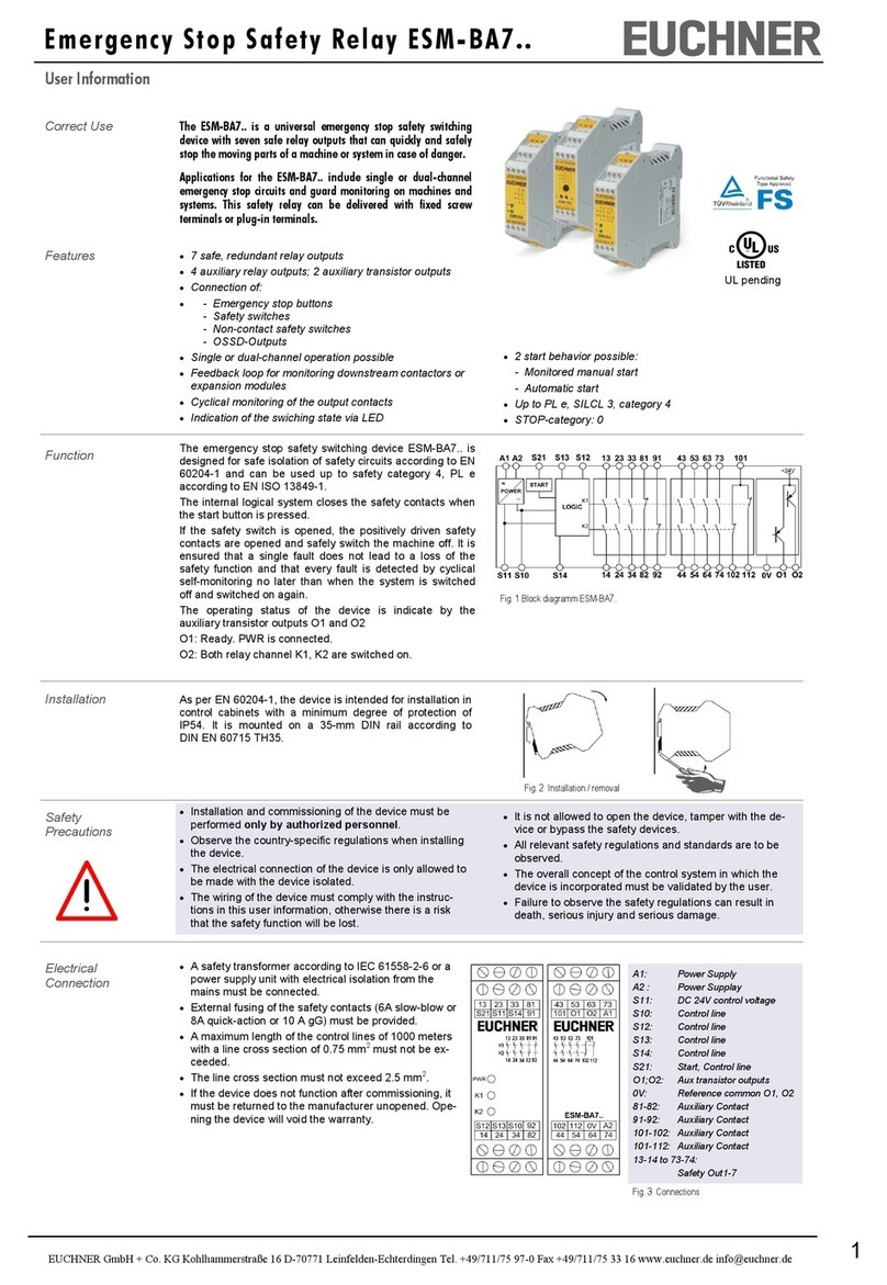
As per EN60204-1, the device is intended for in-
stallation in control cabinets with a minimum degree
of protection of IP54. It is mounted on a 35 mm
mounting rail according to DINEN60715TH35.
Fig. 2: Mounting/removing
Electrical connection
fA safety transformer according to EN61558-2-6
or
a power supply unit with electrical isolation from
the mains must be connected.
fExternal fusing of the safety contacts must be
provided.
fA maximum length of the control lines of 1,000 m
with a conductor cross-section of 0.75mm² must
not be exceeded.
fThe conductor cross-section must not exceed
2.5mm².
fIf the device does not function after setup, it must
be returned to the manufacturer unopened. Open-
ing the device will void the warranty.
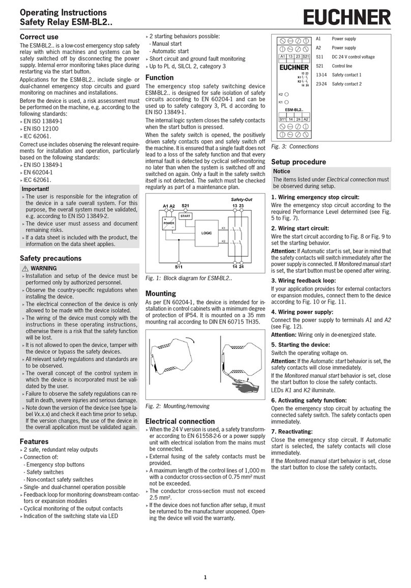
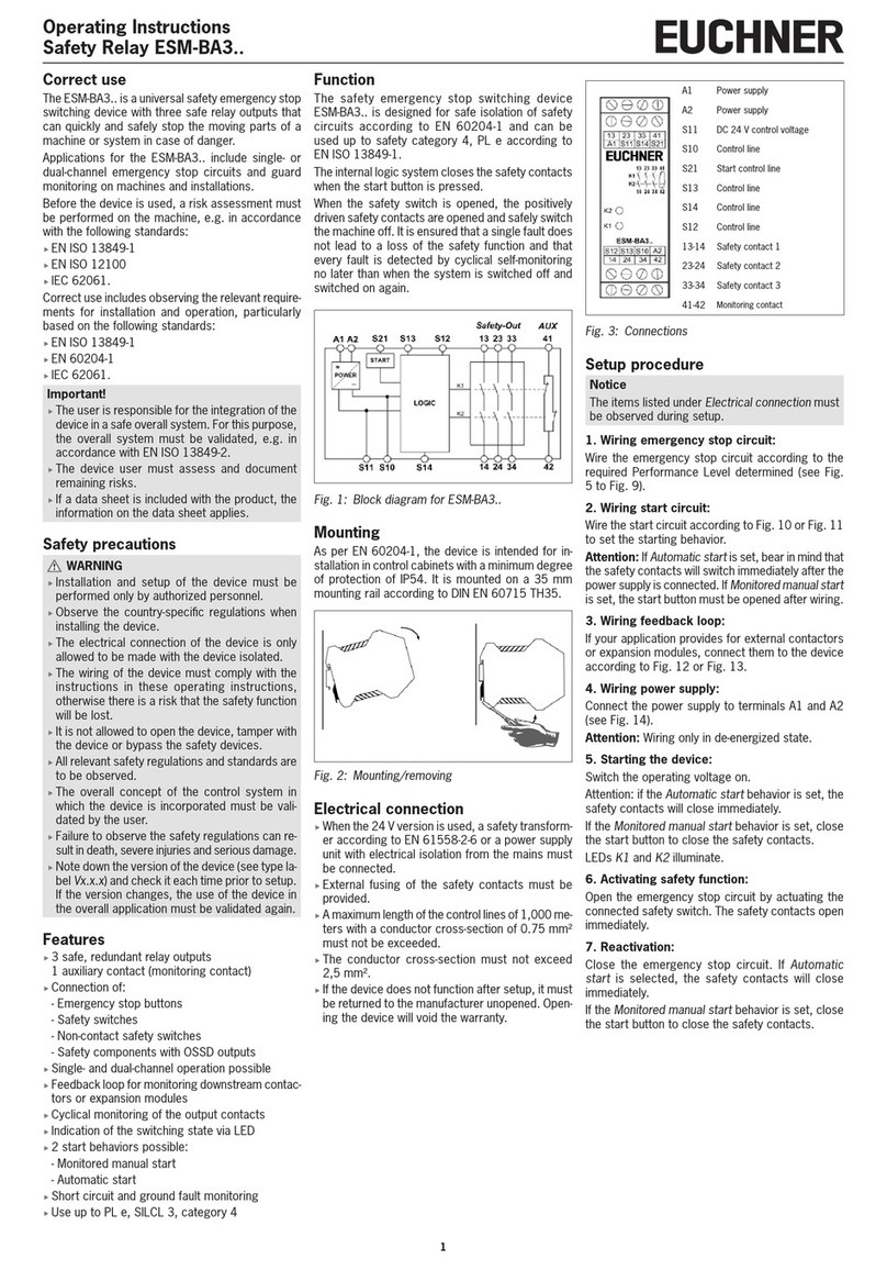
A1 Power supply
A2 Power supply
S11 DC24V control voltage
S10 Control line
S21 Start control line
S13 Control line
S14 Control line
S12 Control line
13-14 Safety contact 1 (u)
23-24 /
27-28 Safety contact 2 (u / v)
33-34 /
37-38 Safety contact 3 (u / v)
47-48 Safety contact 4 (v)
Fig. 3: Connections
(u=non-time-delayed, v=time-delayed)
Setup procedure
Notice
The items listed under Electrical connection must
be observed during setup.
1. Wiring emergency stop circuit:
Wire the emergency stop circuit according to the
required Performance Level determined (see Fig.
5 to Fig. 9).
2. Wiring start circuit:
Wire the start circuit according to Fig. 10 or Fig. 11
to set the starting behavior.
Attention: If Automatic start is set, bear in mind that
the safety contacts will switch immediately after the
power supply is connected. If Monitored manual start
is set, the start button must be opened after wiring.
3. Wiring feedback loop:
If your application provides for external contactors
or expansion modules, connect them to the device
according to Fig. 12 or Fig. 13.
2
Operating Instructions
Safety Relay ESM-BT4..
4. Wiring power supply:
Connect the power supply to terminals A1 and A2
(see Fig. 14).
Attention: Wiring only in de-energized state.
5. Setting delay time:
Set the required time delay on the potentiometer (not
necessary for variants with xed time).
Attention: Tick marks should be regarded only as
a setting aid. Always make sure to measure the
delay time.
6. Starting the device:
Switch the operating voltage on.
Attention: If the Automatic start behavior is set, the
safety contacts will close immediately.
If the Monitored manual start behavior is set, close
the start button to close the safety contacts.
LEDs K1, K2, K3 and K4 illuminate.
7. Activating safety function:
Open the emergency stop circuit by actuating the
connected safety switch. The safety contacts open
immediately.
Attention: Measure the delay time.
8. Reactivating:
Close the emergency stop circuit. If Automatic
start is selected, the safety contacts will close
immediately.
If the Monitored manual start behavior is set, close
the start button to close the safety contacts.
What to do in case of a fault?
Device does not switch on:
fCheck the wiring by comparing it to the wiring
diagrams.
fCheck the safety switch used for correct function
and adjustment.
fCheck whether the emergency stop circuit is
closed.
fCheck whether the start button (with manual start)
is closed.
fCheck the operating voltage at A1 and A2.
fIs the feedback loop closed?
Device cannot be switched on again after an
emergency stop:
fCheck whether the emergency stop circuit was
closed again.
fWas the start button opened before closing of the
emergency stop circuit (with manual start)?
fIs the feedback loop closed?
If the fault persists, perform the steps listed under
Setup procedure.
If these steps do not remedy the fault either, return
the device to the manufacturer for examination.
Opening the device is impermissible and will
void the warranty.
Maintenance
The device must be checked once per month for
proper function and for signs of tampering and by-
passing of the safety function. Check the wiring of
the device and activate the emergency stop function.
Check the delay time.
The device is otherwise maintenance-free, provided
that it was installed properly.
Disposal
Pay attention to the applicable national regulations
and laws during disposal.
EU declaration of conformity
The declaration of conformity is part of the operating
instructions, and it is included as a separate sheet
with the device.
The EU declaration of conformity can also be found
at: www.euchner.com
Service
If servicing is required, please contact:
EUCHNER GmbH + Co. KG
Kohlhammerstraße 16
70771 Leinfelden-Echterdingen
Germany
Service telephone:
+49 711 7597-500
E-mail:
support@euchner.de
Internet:
www.euchner.com
3
Operating Instructions
Safety Relay ESM-BT4..
Technical data
Parameter Value
Operating voltage AC/DC 24 V
Rated supply frequency 50 - 60 Hz
Permissible deviation ± 10%
Power consumption DC 24 V AC 24 V
Approx. 4.7 W Approx. 5.3 VA
Control voltage at S11 DC 24 V
Control current Approx. 190 mA
Response delay after actuation of the
buttons <20ms
Safety contacts 4 NO contacts
(3 non-time-delayed / 1 time-delayed, 2 non-time-delayed/ 2 time-delayed, 1 non-time-de-
layed / 3 time-delayed)
Max. switching voltage AC 250 V
Safety contact breaking capacity
(13-14, 23-24, 33-34, 47-48)
AC: 250 V, 2,000 VA, 8 A for ohm resistive load (6 operating cycles/minute)
250 V, 3 A for AC-15
DC: 40 V, 320 W, 8 A for ohm resistive load (6 operating cycles/minute)
24 V, 3 A, for DC-13
Max. cumulative current of all safety
contacts 15 A 1)
Delay time
- ESM-BT4.. 1 … 30 s
- ESM-BT4..-20S 2 s xed
- ESM-BT4..-50S 5 s xed
Minimum contact load 24 V, 5 mA
Contact fuses 10 A gG
Conductor cross-section 0.14 - 2.5 mm²
Max. length of control cable 1,000 m with 0.75 mm²
Contact material AgSnO2
Mech. contact life Approx. 1 x 10⁷
Test voltage 2.5 kV (control voltage/contacts)
Rated impulse withstand voltage, leakage
paths/air gaps 4 kV (DIN VDE 0110-1)
Rated insulation voltage 250 V
Degree of protection IP20
Temperature range -15°C to +40°C 1)
Degree of contamination 2 (DIN VDE 0110-1)
Overvoltage category 3 (DIN VDE 0110-1)
Weight Approx. 250g
Mounting Mounting rail according to DIN EN 60715 TH35
Reliability values according to EN ISO 13849-1 for all variants of the series ESM-BT4 2)
Load (DC-13; 24V) ≤0.1 A ≤1 A ≤2A
nop ≤500,000 cycles ≤350,000 cycles ≤100,000 cycles
T10D 20 years
Category
- Safety contacts time-delayed 3
- Safety contacts non-time-delayed 4
PL e
PFHD
- Safety contacts time-delayed 8.84x10-8 1/h
- Safety contacts non-time-delayed 4.22x10-8 1/h
1) If several ESM-BT4.. are closely spaced under load, the max. cumulative current is 9 A at an ambient temperature of T = 20 °C, 3 A
at T = 30 °C and 1 A at T = 40 °C. If these currents are exceeded, a spacing of 5mm between the devices must be observed.
2) Additional data can be requested from the manufacturer for applications that deviate from these conditions.
Fixed terminals Plug-in terminals
Fig. 4: Dimension drawing for ESM-BT4..
Operating Instructions
Safety Relay ESM-BT4..
4
Subject to technical modications; no responsibility is accepted for the accuracy of this information. © EUCHNER GmbH + Co. KG 2109074-10-08/22 V1.1.0 (translation of the original operating instructions)
Applications
Depending on the application or the result of the risk assessment according to DINENISO13849-1, the device must be wired as shown in Fig. 5 to Fig. 15.
Non-time-delayed safety contacts can be used up to category 4, PL e, time-delayed safety contacts up to category 3, PL e.
Emergency stop circuit
Fig. 5: Dual-channel emergency stop circuit with
short circuit and ground fault monitoring
(category4, up to PLe).
Fig. 6: Dual-channel emergency stop circuit with
ground fault monitoring (category3, up
to PLd).
Fig. 7: Single-channel emergency stop circuit with
ground fault monitoring (category1, up to
PLc).
Notice:
In order to activate earth fault monitoring, the PE
must be connected only to the power supply unit
according to EN 60204-1.
Wire the start circuit in accordance with the applica-
tion according to Bild 10 or Bild 11.
Fig. 8: Dual-channel sliding guard monitoring with
short circuit and ground fault monitoring
(category4, up to PL e).
Fig. 9: Dual-channel emergency stop circuit with pnp
semiconductor outputs / OSSD outputs with
short circuit detection (category4, up to PLe).
Starting behavior
Attention:Safety contacts switch immediately when
the power supply is connected.
Fig. 10: Manual start. Fig. 11: Automatic start (e.g. for applications with a
safety door). Max perm. delay during clos-
ing of the safety switches on S12 and S13:
S12 before S13: 300ms
S13 before S12: any
Feedback loop
Fig. 12: Feedback loop with manual start. Monitor-
ing of externally connected contactors or
expansion modules.
Fig. 13: Feedback loop with automatic start. Mon-
itoring of externally connected contactors
or expansion modules.
Power supply and safety contacts
Fig. 14: Connection of the power supply to terminals
A1 and A2 (power supply according to the
technical data).
Fig. 15:
Connection to switching loads on safety
contacts (example contact conguration.
Differing according to device type. Switching
voltages +V corresponding to technical data).

This manual suits for next models

3

Other EUCHNER Relay manuals

EUCHNER ESM-BA7 Series User manual

EUCHNER

EUCHNER ESM-BA7 Series User manual

EUCHNER ESM-CB User manual

EUCHNER

EUCHNER ESM-CB User manual

EUCHNER ESM-BL2 Series User manual

EUCHNER

EUCHNER ESM-BL2 Series User manual

EUCHNER ESM-BA3 Series User manual

EUCHNER

EUCHNER ESM-BA3 Series User manual

EUCHNER ESM-BA2 Series User manual

EUCHNER

EUCHNER ESM-BA2 Series User manual

EUCHNER ESM-BA2 Series Operation manual

EUCHNER

EUCHNER ESM-BA2 Series Operation manual

EUCHNER ESM-2H2 Series User manual

EUCHNER

EUCHNER ESM-2H2 Series User manual

EUCHNER ESM-BA7 Series Operation manual

EUCHNER

EUCHNER ESM-BA7 Series Operation manual

Popular Relay manuals by other brands

Viessmann 5551 Operation manual

Viessmann

Viessmann 5551 Operation manual

ZIEHL TR250 operating manual

ZIEHL

ZIEHL TR250 operating manual

Elvox 170D Installation and operation manual

Elvox

Elvox 170D Installation and operation manual

AVE 44 074-W Series quick start guide

AVE

AVE 44 074-W Series quick start guide

ZIGBEE ENVILAR ZG302 manual

ZIGBEE

ZIGBEE ENVILAR ZG302 manual

FANOX SIA-C user manual

FANOX

FANOX SIA-C user manual

Seg XRI1-IE manual

Seg

Seg XRI1-IE manual

Pilz PNOZ X2.1VP operating instructions

Pilz

Pilz PNOZ X2.1VP operating instructions

Elko HRN-33 quick guide

Elko

Elko HRN-33 quick guide

Numato 2 Channel USB Relay Module user guide

Numato

Numato 2 Channel USB Relay Module user guide

Omron Sti SR120MP operating instructions

Omron

Omron Sti SR120MP operating instructions

Siemens 3RV1976-3AP3 operating instructions

Siemens

Siemens 3RV1976-3AP3 operating instructions

KAEL VARko-106-TFT manual

KAEL

KAEL VARko-106-TFT manual

Thytronic DTB 49-50 instruction manual

Thytronic

Thytronic DTB 49-50 instruction manual

Kyongbo Electric K-PAM 5500 Series user manual

Kyongbo Electric

Kyongbo Electric K-PAM 5500 Series user manual

Sven OVP-17P user manual

Sven

Sven OVP-17P user manual

ISB SR4001 operating instructions

ISB

ISB SR4001 operating instructions

Pilz PNOZ p1p operating manual

Pilz

Pilz PNOZ p1p operating manual

manuals.online logo
manuals.online logoBrands
  • About & Mission
  • Contact us
  • Privacy Policy
  • Terms and Conditions

Copyright 2025 Manuals.Online. All Rights Reserved.