manuals.online logo
Brands
  1. Home
  2. •
  3. Brands
  4. •
  5. EUCHNER
  6. •
  7. Switch
  8. •
  9. EUCHNER N01 User manual

EUCHNER N01 User manual

4
Operating Instructions
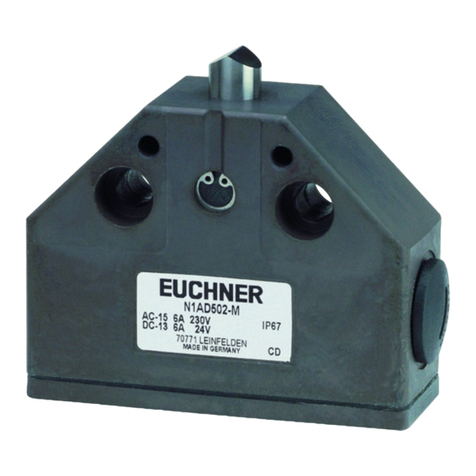
Precision Single Limit Switches N01/NB01/SN01
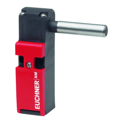
Correct use
Precision single limit switches series N01/NB01/
SN01 are interlocking devices without guard locking
(with safety function). The actuator is uncoded (e.g.
dog). In combination with a movable safety guard
and the machine control, this safety component pre-
vents dangerous machine functions from occurring
while the safety guard is open. A stop command is
triggered if the safety guard is opened during the
dangerous machine function.
For general applications, snap-action switching
elements that are not positively driven are used. For
usage as safety switches, only the switching element
ES588 with positively driven NC contacts is allowed.
This means:
Starting commands that cause a dangerous ma-
chine function must become active only when the
safety guard is closed.
Opening the safety guard triggers a stop com-
mand.
Closing a safety guard must not cause automatic
starting of a dangerous machine function. A
separate start command must be issued. For
exceptions, refer to ENISO12100 or relevant
C-standards.
Devices from this series can be used as safe position
encoders.
Before the device is used, a risk assessment must
be performed on the machine, e.g. in accordance
with the following standards:
ENISO13849-1, Safety of machinery – Safety-re-
lated parts of control systems – Part 1: General
principles for design
ENISO 12100, Safety of machinery – General
principles for design – Risk assessment and risk
reduction
IEC62061, Safety of machinery – Functional
safety of safety-related electrical, electronic and
programmable electronic control systems
Correct use includes observing the relevant require-
ments for installation and operation, particularly
based on the following standards:
ENISO13849-1, Safety of machinery – Safety-re-
lated parts of control systems – Part 1: General
principles for design
ENISO14119, Safety of machinery – Interlocking
devices associated with guards – Principles for
design and selection
EN60204-1, Safety of machinery – Electrical
equipment of machines.
Important!
The user is responsible for the proper integration
of the device into a safe overall system. For this
purpose, the overall system must be validated,
e.g. in accordance with ENISO13849-2.
If the simplied method according to section 6.3
of ENISO13849-1:2015 is used for determining
the Performance Level (PL), the PL might be re-
duced if several devices are connected in series.
Logical series connection of safe contacts is
possible up to PLd in certain circumstances.
More information about this is available in
ISOTR24119.
If a product data sheet is included with the prod-
uct, the information on the data sheet applies
in case of discrepancies with the operating
instructions.
Safety precautions
WARNING
Danger to life due to improper installation or due
to bypassing (tampering). Safety components
perform a personal protection function.
Safety components must not be bypassed,
turned away, removed or otherwise rendered
ineffective. On this topic pay attention in partic-
ular to the measures for reducing the possibility
of bypassing according to ENISO14119:2013,
section 7.
Mounting, electrical connection and setup only
by authorized personnel possessing special
knowledge about handling safety components.
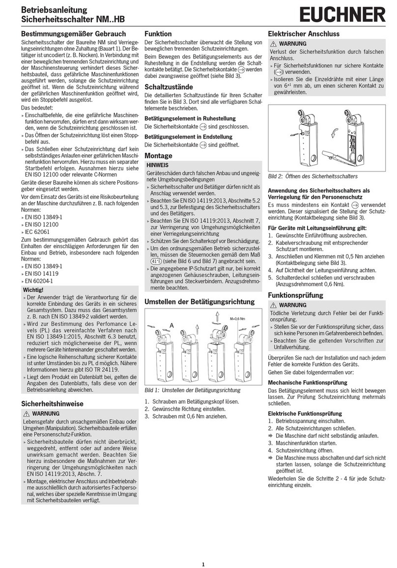
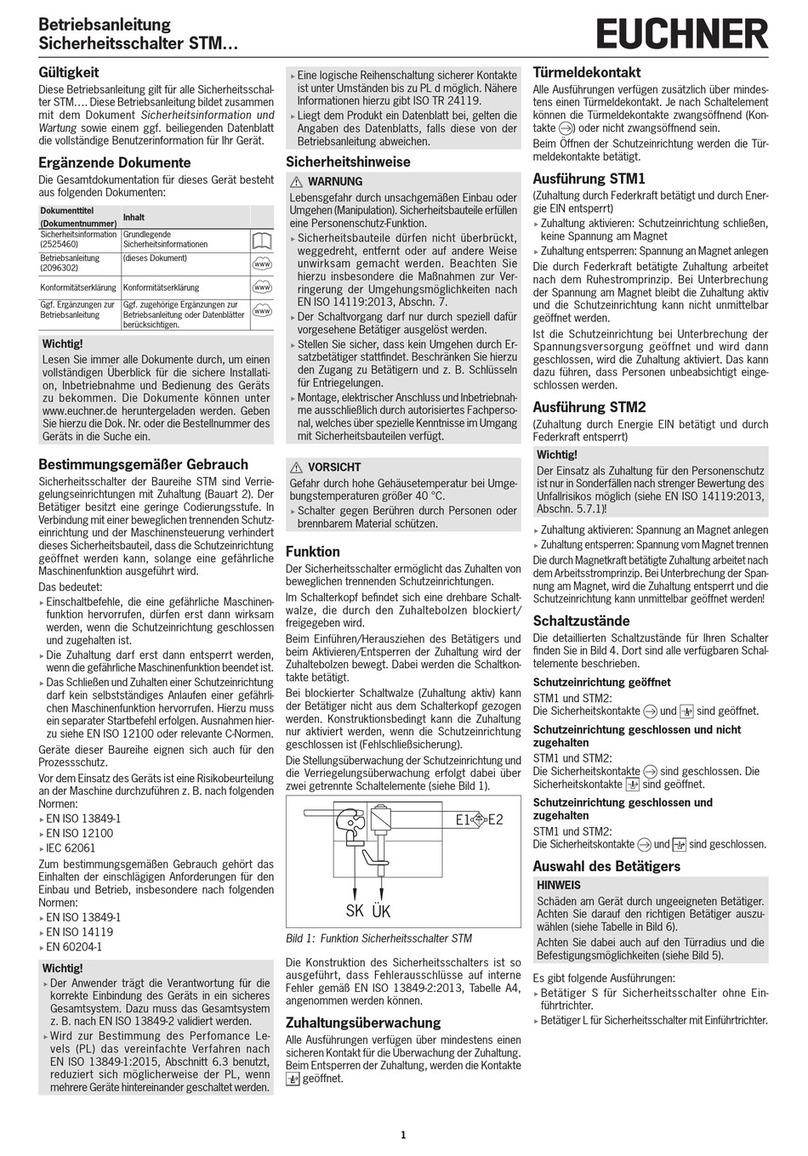
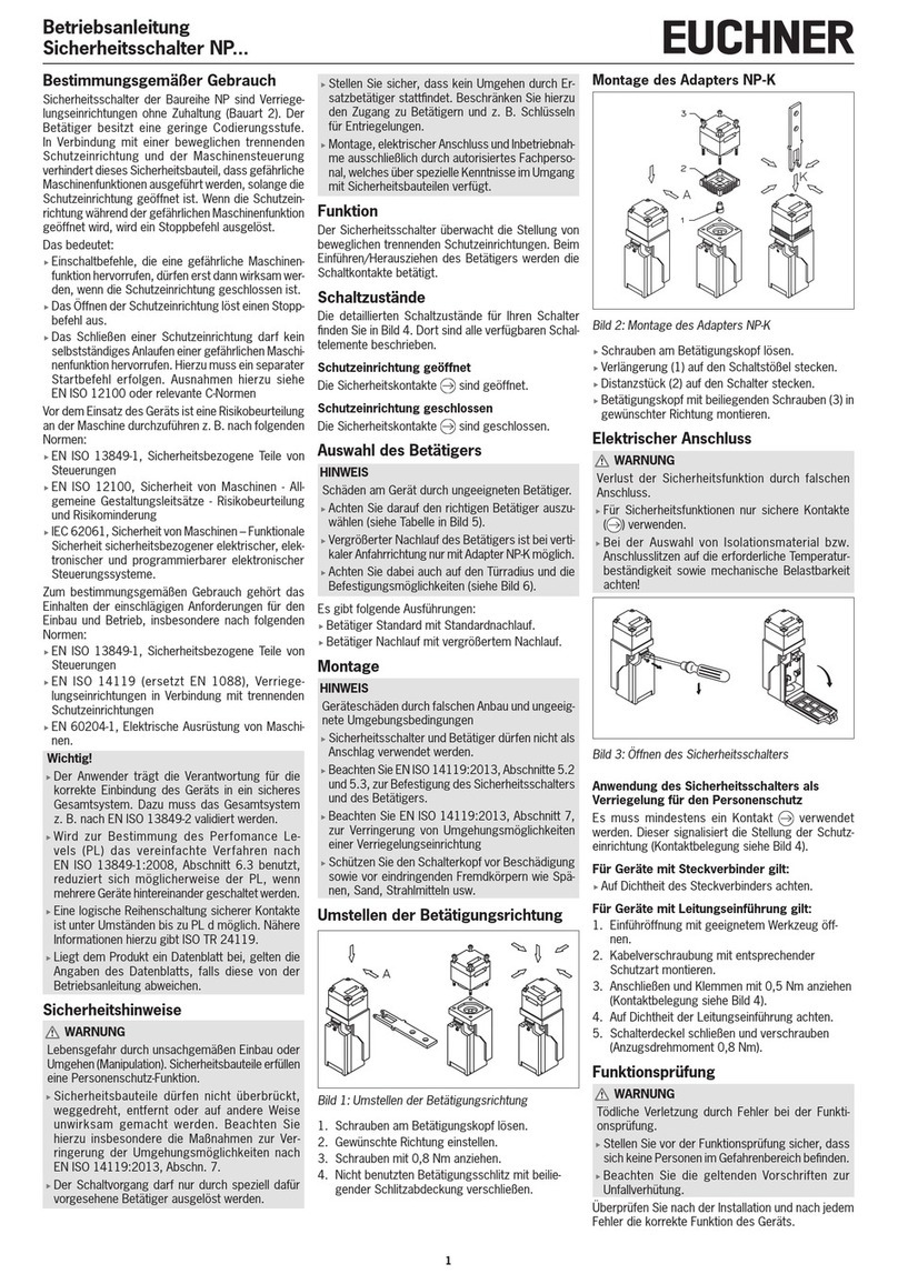
Function
Precision single limit switches are used for posi-
tioning and control applications in mechanical and
systems engineering.
The switching elements are actuated by means of
plungers. Different plunger types and trip dogs are
used depending on the application (operating point
accuracy and approach speed) (see Figure 2).
In general applications the plunger is actuated by
trip dogs in accordance with DIN 69639 which
are mounted with an interference t in trip rails in
accordance with DIN 69638.
The switching contacts are actuated when the actu-
ating element is moved from the free position to the
end position. The safety contacts are positively
opened in this process.
Switching states
The detailed switching states for your switch can be
found in Figure 11. All available switching elements
are described there.
Actuating element in free position
The safety contacts are closed.
Actuating element in end position
The safety contacts are open.
Mounting
NOTICE
Device damage due to improper mounting and
unsuitable ambient conditions.
Safety switches and actuators must not be used
as an end stop.
Observe ENISO14119:2013, sections 5.2 and
5.3, for information about fastening the safety
switch and the actuator.
Observe ENISO 14119:2013, section 7, for
information about reducing the possibilities for
bypassing an interlocking device.
It is imperative that dimension
11
-0,5 (distance
from switch reference surface to trip dog, see
Figure 3) is maintained in safety circuits to ensure
safe contact opening.
Protect the switch head against damage.
Protection against environmental
inuences
Safety venting valves (see Figure 3, for example)
are used to compensate for the pumping action of
the plungers. They must not be sealed with paint.
Mask plunger, plunger guide, safety venting valves
and rating plate during painting work!
Changing the actuating direction
90°
Figure 1: Changing the actuating direction
1. Unscrew the locking screw.
2. Set the required direction.
3. Screw in the locking screw again.
Electrical connection
WARNING
Loss of the safety function due to incorrect
connection.
Use only safe contacts ( ) for safety functions.
Use of the safety switch as an interlocking
device for personnel protection
At least one contact must be used. This signals
the position of the safety guard (for terminal assign-
ment, see Figure 11).
The following information applies to devices
with plug connector:
Check that the plug connector is sealed.
The following information applies to devices
with cable entry:
1. Use a suitable tool to open the desired inser-
tion opening.
2. Fit the cable gland with the appropriate degree
of protection.
3. Connect and tighten the terminals (for terminal
assignment, see Figure 11; for tightening
torque values, see technical data).
4. Check that the cable entry is sealed.
5. Close the switch cover and screw in place
(tightening torque 0.5 Nm).
Function test
WARNING
Fatal injury due to faults during the function test.
Before carrying out the function test, make sure
that there are no persons in the danger area.
Observe the valid accident prevention regula-
tions.
Check the device for correct function after installa-
tion and after every fault.
Proceed as follows:
Mechanical function test
The actuating element must move easily. Close the
safety guard several times to check the function.
Electrical function test
1. Switch on operating voltage.
2. Close all safety guards.
 The machine must not start automatically.
3. Start the machine function.
4. Open the safety guard.
 The machine must switch off and it must not be
possible to start it as long as the safety guard
is open.
Repeat steps 2 - 4 for each safety guard.
Inspection and service
WARNING
Danger of severe injuries due to the loss of the
safety function.
In safety circuits, the entire switch must be re-
placed in case of damage or wear. Replacement
of individual parts or assemblies is not permitted.
Check the device for proper function at regular
intervals and after every fault. For informa-
tion about possible time intervals, refer to
ENISO14119:2013, section 8.2.
Inspection of the following is necessary to ensure
trouble-free long-term operation:
correct switching function
secure mounting of all components
precise adjustment of trip dog in relation to single
limit switch
damage, heavy contamination, dirt and wear
5
Operating Instructions
Precision Single Limit Switches N01/NB01/SN01
sealing of cable entry
loose cable connections or plug connectors.
Information: The year of manufacture can be seen
in the bottom, right corner of the rating plate.
Exclusion of liability and warranty
In case of failure to comply with the conditions for
correct use stated above, or if the safety instruc-
tions are not followed, or if any servicing is not
performed as required, liability will be excluded and
the warranty void.
Notes about
The following information applies to devices
with plug connector:
For use and applications as per the requirements of
, a class 2 power supply according to UL1310
must be used. Connection cables for safety switches
installed at the place of use must be separated
from all moving and permanently installed cables
and un-insulated active elements of other parts
of the system which operate at a voltage of over
150 V. A constant clearance of 50.8 mm must be
maintained. This does not apply if the moving cables
are equipped with suitable insulation materials which
possess an identical or higher dielectric strength
compared to the other relevant parts of the system.
EU declaration of conformity
The declaration of conformity is part of the operating
instructions, and it is included as a separate sheet
with the unit.
The original EU declaration of conformity can also be
found at: www.euchner.com
Service
If service support is required, please contact:
EUCHNER GmbH + Co. KG
Kohlhammerstraße 16
D-70771 Leinfelden-Echterdingen
Service telephone:
+49 711 7597-500
Fax:
+49 711 753316
E-mail:
support@euchner.de
Internet:
www.euchner.de
Technical data
Parameter Value
Housing material Die-cast aluminum,
anodized
Plunger material Stainless steel
Degree of protection IP 67
Mech. operating cycles 30 x 106
Ambient temperature with switching element
ES550/553/556/558/562/620 -5 ... +80 °C
ES572 (high temp. version)
-5 ... +125 °C
(200 h at 180 °C)
ES588 -25 ... +70 °C
ES560/593 -5 ... +125 °C (manufac-
turer’s data max. +140 °C)
Installation position Any
Max. approach speed
Plunger Chisel D 20 m/min
Roller R (slide bearing) 50 m/min
Ball K 8 m/min
Min. approach speed 0.01 m/min
Actuating force with switching element ≥15 N
Switching element
ES550/553/556/560/562/572/
593/620
1 changeover contact
ES558 1 NC contact + 1 NO
contact
ES588 1 positively driven contact
Switching principle
ES550/553/556/558/560/562/
572/593/620
Snap-action switching
contact
ES588 Positively driven slow-ac-
tion switching contact
Switching hysteresis
ES550/553/556/560/562/572/
593/620
max. 0.1 mm
ES558 0.5 mm
Connection
ES550/558/560/562/572/593 Soldered connection
ES553/556/588/620 Screw terminal
Tightening torque of screw terminal
ES553/556 (hexagon socket head
screw, AF 1.3 mm) 0.2 Nm
ES588 (slot head screw) 0.3 Nm
ES620 (slot head screw) 0.5 Nm
Conductor cross-section
ES553/556/620 0.14 ... 1.0 mm²
ES588 max. 1.5 mm²
Contact material
ES550/553/556/558/572/588/
593/620 Silver
ES560/562 Gold cross cut contacts
Rated impulse withstand voltage
with cable entry Uimp = 2.5 kV
with plug connector, 4-pin Uimp = 2.0 kV
with plug connector, 5-pin Uimp = 1.5 kV
Rated insulation voltage
with cable entry Ui= 250 V
with plug connector Ui= 50 V
with B-coded plug connector Ui= 250 V
Rated short-circuit current 100 A
Rated data for the switching elements
ES558
Conventional thermal current Ith 10 A
Utilization category AC-15 230 V/4 A
Utilization category DC-13 24 V/3 A
Min. switching current at 10 mA
Switching voltage DC 5 V
Short circuit protection 10 A gG
Mechanical life Up to 10 x 106operating
cycles
ES550/553/556/620
Conventional thermal current Ith 6 A
Utilization category AC-15 230 V/2 A
Utilization category DC-13 24 V/2 A
Min. switching current at 10 mA
Switching voltage DC 24 V
Short circuit protection 6 A gG
Mechanical life Up to 10 x 106operating
cycles
ES560
Conventional thermal current Ith 2 A
Utilization category DC-12 30 V/1 A
Min. switching current at 1 mA
Switching voltage DC 5 V
Short circuit protection 2 A gG
Mechanical life Up to 10 x 106operating
cycles
Ideal application 1 mA/5 V … 0.3 A/30 V
ES562
Conventional thermal current Ith 0.1 A
Utilization category AC-12 30 V/0.1 A
Utilization category DC-13 30 V/0.1 A
Min. switching current at 5 mA
Switching voltage DC 5 V
Short circuit protection 0.125 A gG
Mechanical life Up to 15 x 106operating
cycles
ES572 (high temperature version)
Conventional thermal current Ith 5 A
Utilization category AC-15 230 V/4 A
Utilization category DC-13 24 V/1 A
Min. switching current at 10 mA
Switching voltage DC 12 V
Short circuit protection 5 A gG
Mechanical life 5 x 10⁵operating cycles
(or 100 h at 204 °C;
manufacturer’s data)
ES588
Conventional thermal current Ith 10 A
Utilization category AC-15 230 V/4 A
Utilization category DC-13 24 V/3 A
Min. switching current at 1 mA
Switching voltage DC 5 V
Short circuit protection 10 A gG
Mechanical life Up to 10 x 106operating
cycles
ES593
Conventional thermal current Ith 3 A
Utilization category AC-15 230 V/3 A
Utilization category DC-13 24 V/1 A
Min. switching current at 10 mA
Switching voltage DC 24 V
Short circuit protection 3 A gG
Mechanical life 5 x 10⁵operating cycles
(manufacturer’s data 5 x 10
6
)
Rated data with plug connector
N01.550SVM5
Utilization category AC-15 30 V/2 A
Utilization category DC-13 24 V/2 A
N01.550C1526
Utilization category DC-13 24 V/2 A
SN01.558SVM5
Utilization category AC-15 30 V/4 A
Utilization category DC-13 24 V/3 A
Reliability values acc. to EN ISO 13849-1 for NB01 with
switching element ES588
B10d 2 x 10⁷
Figure 2: Plungers and approach directions
R2,5
R2,0
120 -0,5
Preferred approach directions
D = chisel R = roller K = ball
Operating Instructions
Precision Single Limit Switches N01/NB01/SN01
6
Subject to technical modications; no responsibility is accepted for the accuracy of this information. © EUCHNER GmbH + Co. KG 2105376-07-04/19 (translation of the original operating instructions)
20
∅6
25
∅8
9,5
11
27
40
a
M12x1,5
4,2
3
0°
max.
13,5
12,5
-0,5
±0,3
l
∅4,3 (∅4,5 H7)
Operating
point
Free position
Type Dimen-
sion a
[mm]
Dimen-
sion l
[mm]
N01... 2 40
NB01.556-M 2 44
NB01.588-M 2 58
NB01.620-M 6 48.5
Figure 3: Dimension drawing of N01.../NB01... with cable entry
Plunger type
depending on
type
On switching element ES588
the safe positive opening
function is dependent on
observance of the dimension
11
-0,5
.
Dog
Safety
venting
valve
Figure 4: Dimension drawing/connection diagram of N01.550X... with con-
nection cable (PUR cable, 4x0.5 mm²)
20
Cable gland
M12x1.5
GNYEBUBK
BN
C
NO
NC
For version C2043
silicone cable
Figure 5: Dimension drawing/connection diagram of N01.550/562SVM5 with
plug connector M12 (SVM5, 5-pin)
45°
24
26,5
31
Right-angle plug connector, cable outlet adjustable,
max. 270°.
Standard position:
Cable outlet downwards.
Guide lug aligned
WH
BU
BKBN
234
1
C
NO
NC
GNYE
Figure 6: Dimension drawing/connection diagram of N01.550C1526 with
plug connector M12 (4-pin)
≥45
35
15
Inserted
Right-angle plug connector
+
GN
YE
WH
BU
BKBN
234
1
C
NO
NC
Figure 7: Dimension drawing of N01...MC2018/NB01.620-MC2018 with
special cable gland
2
M12 x 1.5
For cable diameter 4.5 ...
6.5 mm
N01...MC2018 NB01.620-MC2018
6
M12 x 1.5
For cable diameter 4.5 ...
6.5 mm
∅6
9,5
11
13,5
27
30
°
max.
M16x1,5
50
22
45
∅8
25
4,2
12,5
±0,3
∅4,3 (∅4,5 H7)
Operating
point
Free position
Plunger type
depending on
type
Dog
Figure 8: Dimension drawing of SN01.. with cable entry
Safety venting
valve
Figure 9: Dimension drawing/connection diagram of SN01.558X... with con-
nection cable (PUR cable, 5x0.5 mm²)
20
Cable gland
M16x1.5
BN
21
21
22
BK
4
14
BU
3
GNYE
13
BK
Figure 10: Dimension drawing/connection diagram of SN01.558SVM5 with
plug connector M12 (SVM5, 5-pin)
20
45°
26,5
31
Right-angle plug connector, cable outlet adjustable,
max. 270°.
Standard position:
Cable outlet downwards.
Guide lug aligned
WHBN
2
1
21
22
BK
4
14
BU
3
GNYE
13
Figure 11: Switching elements, wiring diagrams and terminal assignment of
N01.../NB01.../SN01... with cable entry
Switching
element Wiring diagram Terminal assignment
ES550
ES560
ES593
1
4(NO)
2(NC)
(C)
241
ES553
124
ES556
ES562
241
ES572
241
ES620
124
ES558
1 (NC
)
2 (NC)
4 (NO)
3 (NO)
4213
ES588 1
2(NC)
(C)

Other manuals for N01

2

This manual suits for next models

5

Other EUCHNER Switch manuals

EUCHNER CTS-C2-BP/BR-FLX User manual

EUCHNER

EUCHNER CTS-C2-BP/BR-FLX User manual

EUCHNER STP Series User manual

EUCHNER

EUCHNER STP Series User manual

EUCHNER NZ H/P Series User manual

EUCHNER

EUCHNER NZ H/P Series User manual

EUCHNER TZ Series User manual

EUCHNER

EUCHNER TZ Series User manual

EUCHNER NZ VZ Series User manual

EUCHNER

EUCHNER NZ VZ Series User manual

EUCHNER CES-I-AS2A Series Original instructions

EUCHNER

EUCHNER CES-I-AS2A Series Original instructions

EUCHNER TZ1RE024MVAB-C1623 User manual

EUCHNER

EUCHNER TZ1RE024MVAB-C1623 User manual

EUCHNER CES-AP-C01- Series User manual

EUCHNER

EUCHNER CES-AP-C01- Series User manual

EUCHNER NZ.VZ-VS Series User manual

EUCHNER

EUCHNER NZ.VZ-VS Series User manual

EUCHNER STP AS1 Series User manual

EUCHNER

EUCHNER STP AS1 Series User manual

EUCHNER CES-I-AR-.-C04 Series User manual

EUCHNER

EUCHNER CES-I-AR-.-C04 Series User manual

EUCHNER STA3A-4141A024L024M User manual

EUCHNER

EUCHNER STA3A-4141A024L024M User manual

EUCHNER NM KB Series User manual

EUCHNER

EUCHNER NM KB Series User manual

EUCHNER STP-TW Series User manual

EUCHNER

EUCHNER STP-TW Series User manual

EUCHNER CES-AP-CR2-CH User guide

EUCHNER

EUCHNER CES-AP-CR2-CH User guide

EUCHNER CMS-AS1 User manual

EUCHNER

EUCHNER CMS-AS1 User manual

EUCHNER CTM-L2-AS1B Unicode User manual

EUCHNER

EUCHNER CTM-L2-AS1B Unicode User manual

EUCHNER CES-AH-C03-AH-SM User manual

EUCHNER

EUCHNER CES-AH-C03-AH-SM User manual

EUCHNER CTP-I.-AS Unicode Series User manual

EUCHNER

EUCHNER CTP-I.-AS Unicode Series User manual

EUCHNER N01 User manual

EUCHNER

EUCHNER N01 User manual

EUCHNER TZ1LE024RC18VAB-C1828 User manual

EUCHNER

EUCHNER TZ1LE024RC18VAB-C1828 User manual

EUCHNER CES-A-5 Series User manual

EUCHNER

EUCHNER CES-A-5 Series User manual

EUCHNER NZ H AS1 Series User manual

EUCHNER

EUCHNER NZ H AS1 Series User manual

EUCHNER SGA Series User manual

EUCHNER

EUCHNER SGA Series User manual

Popular Switch manuals by other brands

Kasia Switch installation guide

Kasia

Kasia Switch installation guide

Banner SI-RF Series installation manual

Banner

Banner SI-RF Series installation manual

ATEN CS1912 user manual

ATEN

ATEN CS1912 user manual

TRENDnet TK-400K - KVM Switch - PS/2 Quick installation guide

TRENDnet

TRENDnet TK-400K - KVM Switch - PS/2 Quick installation guide

Leonton PT2-0802-2C-24 Series user manual

Leonton

Leonton PT2-0802-2C-24 Series user manual

Net Optics iBypass user guide

Net Optics

Net Optics iBypass user guide

Cabletron Systems MMAC-Plus 9T125-08 reference guide

Cabletron Systems

Cabletron Systems MMAC-Plus 9T125-08 reference guide

Lindy 38030 user manual

Lindy

Lindy 38030 user manual

LIBERTY AV SOLUTIONS DigitaLinx DL-3H1U-WP-W Quick install guide

LIBERTY AV SOLUTIONS

LIBERTY AV SOLUTIONS DigitaLinx DL-3H1U-WP-W Quick install guide

Honeywell BX Series installation instructions

Honeywell

Honeywell BX Series installation instructions

Festo SME-CDC-DS-24V-SQM8 manual

Festo

Festo SME-CDC-DS-24V-SQM8 manual

ZyXEL Communications AAM1212 user guide

ZyXEL Communications

ZyXEL Communications AAM1212 user guide

Lindy 32254 user guide

Lindy

Lindy 32254 user guide

ABB ATS022 Installation and operating instructions

ABB

ABB ATS022 Installation and operating instructions

GarrettCom Magnum 6K32T Hardware user manual

GarrettCom

GarrettCom Magnum 6K32T Hardware user manual

Allied Telesis AT-9108 installation guide

Allied Telesis

Allied Telesis AT-9108 installation guide

Inteno FG101 user manual

Inteno

Inteno FG101 user manual

TRENDnet TK-209K Quick installation guide

TRENDnet

TRENDnet TK-209K Quick installation guide

manuals.online logo
manuals.online logoBrands
  • About & Mission
  • Contact us
  • Privacy Policy
  • Terms and Conditions

Copyright 2025 Manuals.Online. All Rights Reserved.