Euresys Picolo.net HD1 1669-DR User manual

Picolo.net
Picolo.net HD1 - Firmware Version 2.6
GETTING STARTED
© EURESYS s.a. 2020 - Document D302ET-Getting Started-Picolo.net_HD1-2.6.9.3032built on 2020-03-25

2
Terms of Use
EURESYS s.a. shall retain all property rights, title and interest of the documentation of the hardware and the
software, and of the trademarks of EURESYS s.a.
All the names of companies and products mentioned in the documentation may be the trademarks of their
respective owners.
The licensing, use, leasing, loaning, translation, reproduction, copying or modification of the hardware or the
software, brands or documentation of EURESYS s.a. contained in this book, is not allowed without prior notice.
EURESYS s.a. may modify the product specification or change the information given in this documentation at any
time, at its discretion, and without prior notice.
EURESYS s.a. shall not be liable for any loss of or damage to revenues, profits, goodwill, data, information systems or
other special, incidental, indirect, consequential or punitive damages of any kind arising in connection with the use
of the hardware or the software of EURESYS s.a. or resulting of omissions or errors in this documentation.
This documentation is provided with Picolo.net 2.6.9 (doc build 3032).
© 2020 EURESYS s.a.
Picolo.net Getting Started

3
Contents
1. Description 5
1.1. Short Description 5
1.2. Video Processing Chain 9
1.3. Access Control 11
1.4. Precautions of Use 13
2. Installing a Picolo.net 14
2.1. Disclaimer 15
2.2. Declarations of Conformity 15
2.3. Installation 17
2.4. Connectors Location and Markings 18
2.5. Connections 18
2.6. Configuration 21
2.7. Final Check 23
2.8. Upgrading the Firmware 23
2.9. Configuring Backup and Restore 24
3. Hardware Specifications 25
3.1. Mechanical Specifications 25
Dimensions and Weight 25
Mounting Methods 25
Connectors Location and Pinout 26
LED Indicators 28
Switches 29
3.2. Electrical Specifications 31
Power Input 31
SDI Input Port 32
HDMI Input Port 32
HDMI Output Port 33
Analog Audio Input Port 33
Analog Audio Output Port 33
Alarm Input Port 34
Relay Output Port 35
RS-232 COM Port 36
RS-422/RS-485 COM Port 37
USB Port 37
Picolo.net Getting Started

4
Power Supply Adapters 38
3.3. Environmental Specifications 39
Operating Conditions 39
Storage Conditions 40
Compliance 40
3.4. Functional Specifications 42
Video Source Specification 42
Video Encoders Specification 43
Audio Specifications 45
Streaming Specifications 47
Network Specifications 49
System Integration Specifications 51
Temperature Monitor 52
Time and Date 52
4. Software Specifications 54
4.1. Software Components 54
4.2. Client Interfaces 58
4.3. AES Storage Control Interface 59
Picolo.net Getting Started

5
1. Description
1.1. Short Description
Left: 1669-DR Picolo.net HD1 (DIN rail) and right: 1669-DW Picolo.net HD1 (Desktop/Wall)
Picolo.net HD1
Deliverables
Quantity Items
1
Enclosure:
□1669-DR Picolo.net HD1 (DIN rail)
□1669-DW Picolo.net HD1 (Desktop/Wall)
1 8-pin (1x8) 3.81mm pitch terminal plug
1 4-pin (1x4) 3.81mm pitch terminal plug
1 2-pin (1x2) 3.81mm pitch terminal plug
1 Picolo.net HD1 Installation Guide
Picolo.net Getting Started 1. Description

6
Product accessories
Order Code and Name Short Description
1675 Power Supply for Picolo.net HD1
Universal power supply:
□110-240Vac, 50/60 Hz input
□12Vdc, 40W output
1660 Power Cable (EUR) IEC C13 AC power cord with CEE 7/7 plug – 1.8m
1661 Power Cable (US) IEC C13 AC power cord with US 3-pin plug – 6ft
1662 Power Cable (UK) IEC C13 AC power cord with UK 3-pin plug – 6ft
Key features
Picolo.net HD1 provides the following key features:
□High-quality HEVC (H.265) / AVC (H.264) encoder, up to 9 encoded streams
□Video streaming from one full HD (up to 1080p60/1080i60) HDMI or SDI source
□ONVIF Profile S and Profile T interface
□Video encryption
□Hi-Fi AAC or uncompressed audio
□USB edge storage / USB GPS support
□Serial connection for PTZ cameras
□PoE+ Power over Ethernet
□Fanless aluminum housing
Video features
Picolo.net HD1 acquires high-definition video from one of HDMI or SDI video sources.
It supports progressive-scan formats up to 1080p60 and interlaced formats up to 1080i60 with a
large set of frame rates for both 50Hz and 60Hz regions. The source selection and the format
selection are automatic.
Interlaced-scan video streams are converted to progressive-scan with motion-compensation.
Two scalers provide two additional video stream sources at lower (or higher) resolutions :
□The scaler #1 scales the source resolution to 1280 x 720 (720p) (or lower).
□The scaler #2 scales the source resolution to 640 x 360 (360p) (or lower).
Picolo.net Getting Started 1. Description

7
The three streams can be encoded concurrently with any of the following encoding methods:
□HEVC (H.265) main profile,
□AVC (H.264) baseline, main, or high profiles,
□MJPEG.
The high-quality HEVC (H.265) / AVC (H.264) hardware encoder engine is capable of encoding
multiple streams with an aggregate pixel rate up to 160,000,000 pixels per second (equivalent to
1080p77).
The MJPEG encoder is capable of encoding multiple streams with an aggregate pixel rate up to
62,208,000 pixels per second (equivalent to 1080p30).
Audio features
Picolo.net HD1 acquires 2-channel audio from one of HDMI, SDI or analog audio sources.
The source selector provides three options:
□HDMI: two digital audio channels embedded in the HDMI audio/video signal,
□SDI: two digital audio channels are embedded in the SDI audio/video signal,
□Analog: two digital audio channels delivered by the 48 kHz 16-bit analog-to-digital
converter in the analog audio input interface.
The sample rate converter allows to change the sample rate of the selected audio stream. The
resulting audio stream can be delivered in the uncompressed format (e.g. 16-bit LPCM), in the
AAC-LC compressed format or in the G.711 format.
IO Features
Picolo.net HD1 provides the following I/O features:
□Two USB2.0 ports for external storage device and GPS receiver,
□Two serial COM ports for the control of PTZ cameras: one with a full-duplex RS-422/half-
duplex RS-485 interface using the Pelco-D protocol and one with a full-duplex RS-232
interface using the VISTA protocol.
□One alarm input port,
□One relay output port.
Network features
Picolo.net HD1 provides a gigabit capable RJ-45 Ethernet port for connection to an IP network.
Streaming features
Picolo.net HD1 uses the Real-time Transport Protocol - RTP - to stream audio, video and
metadata over the IP network. The following RTP transport modalities are supported:
□RTP over UDP Unicast
□RTP over UDP Multicast
Picolo.net Getting Started 1. Description

8
□RTP interleaved in RTSP over HTTP or HTTPS
The streaming is controlled by means of the RTSP protocol. Each RTSP session may include:
□One encoded video stream
□One encoded audio stream
□One metadata stream
User authentication and access policy
Picolo.net HD1 implements the following user authentication mechanisms to control the access
to its resources:
□HTTP and RTSP authentication using the "HTTP Digest Authentication" mechanism
□WS authentication using the WS-Security “Username Token” mechanism, with the
“Password Digest” password type.
□Web Pages through login/password dialog box.
Encryption
Picolo.net HD1 implements the following encryption mechanisms:
□Web Service messages encryption using TLS 1.0
□HTTPS Web Pages encrypted access using TLS 1.0
□Optional AES-128 encryption and transparent decryption of the files written on USB mass
storage devices.
Compliance
Picolo.net HD1 is an encoder device complying with the version 1.0 of the ONVIF Profile S
Specification.
Physical
Picolo.net HD1 (DIN rail) is packaged in an aluminum enclosure that can be fitted on a DIN-rail.
Picolo.net HD1 (Desktop/Wall) is packaged in an aluminum enclosure that can be installed on a
desktop or attached to any flat surface such as a wall.
Picolo.net HD1 products are:
□intended for indoor use exclusively,
□fan-less devices that support ambient temperatures up to 50°C or 122°F,
□powered from an external 12V DC power source or from a PoE+ network device.
Picolo.net Getting Started 1. Description
9
1.2. Video Processing Chain
Video Processing Chain
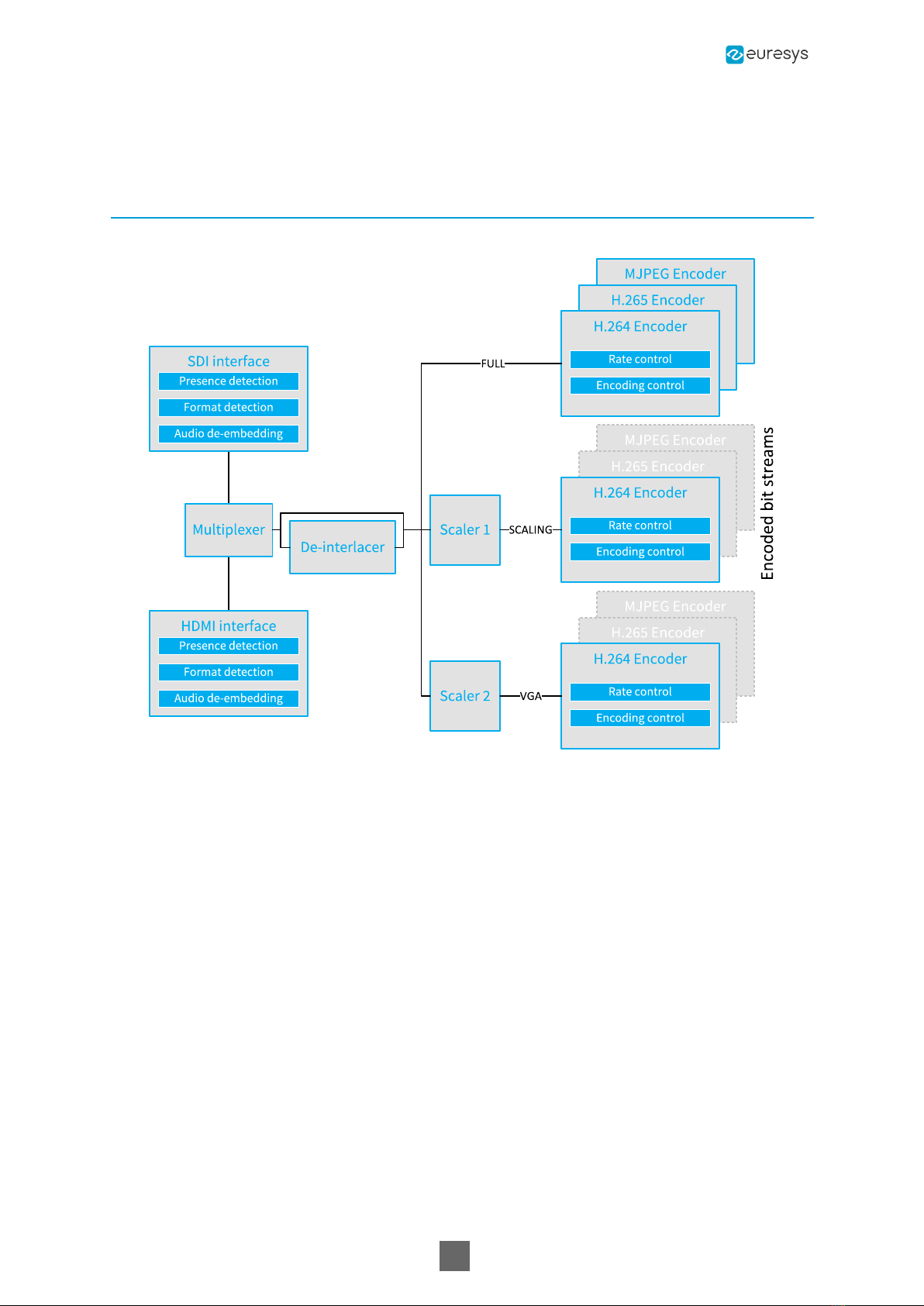
The video processing chain is composed of the following elements:
□One video front end including 2 video interfaces, 1 video source multiplexer, 1 video de-
interlacer,
□Two video scalers,
□Three video encoders.
Video front end
●The video multiplexer selects the SDI source or the HDMI source. The SDI interface
implements a 3G-SDI receiver capable of automatically identifying and decoding HD-SDI and
3G-SDI audio/video signals up to 1080p60. The HDMI interface implements a single-link HDMI
1.4 receiver capable of automatically identifying and decoding audio/video signals up to
1080p30.
●The de-interlacer converts interlaced-scan video streams to progressive-scan video streams
keeping the native resolution and the native frame rate of the video
●The progressive scan video stream is fed to the three encoders and to the two scalers.
Picolo.net Getting Started 1. Description
10
Video scalers
●The two video scalers scale down (or up) the full resolution progressive scan video stream:
●The video scaler #1 delivers a video data stream having a resolution up to 1280 pixels wide
(720p).
●The video scaler #2 deliver a video data stream having a resolution up to 640 pixels wide
(480p).
●The video scalers are exposed to the user as additional encoders that have access to a
restricted set of resolutions.
Video encoders
●There are three video encoders: one AVC (H.264), one HEVC (H.265) and one MJPEG encoder.
●Multiple video encoders can be instantiated, processing either unscaled video streams, or one
of the video scalers output.
●Free mixing of AVC (H.264) and HEVC (H.265) encoding is allowed as long as the total amount
of data to encode does not exceed 160 Mega-pixels per second.
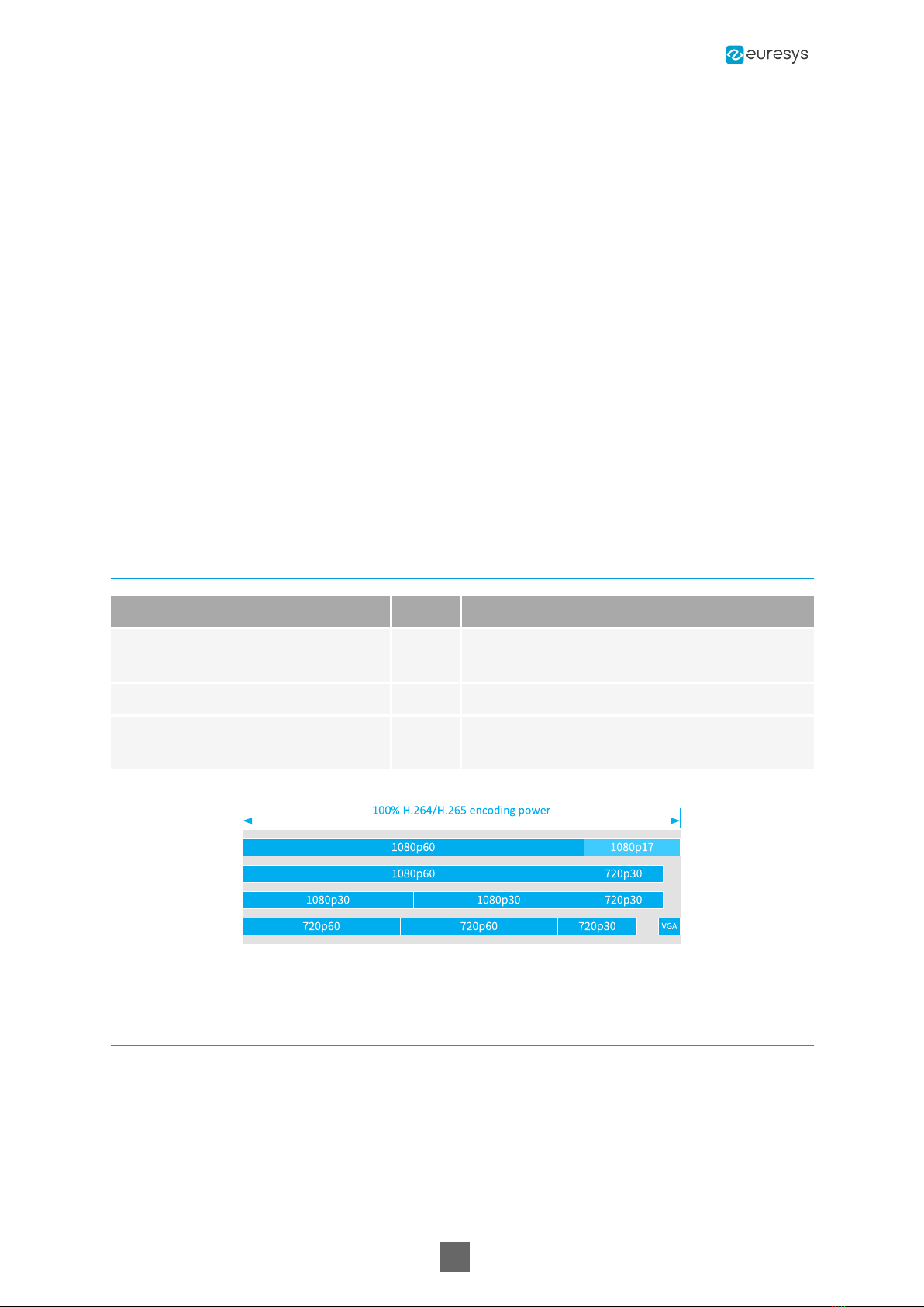
Video Processing Capabilities
Property Value Note
AVC (H.264) encoded streams count 3 0 or 1 stream for each available resolution
(full, scaler #1, scaler #2)
Frame rate control Yes
Total H.264/H.265 encoding power
[Mpixels/second] 160 Equivalent to 77 frames of 1920 x 1080 pixels
per second
H.264/H.265 encoding power requirements for some stream combinations
Programming Model
The application software manages the video processing resources using one ONVIF Media Profile
for each encoded video stream.
An ONVIF Media Profile associates one VideoSourceConfiguration and one
VideoEncoderConfiguration.
Picolo.net Getting Started 1. Description

11
1.3. Access Control
Access Policy
Picolo.net HD1 products implement the default access policy that is recommended by the ONVIF
2.2 Core Specification.
The policy implements four user levels Administrator, Operator, User, and Anonymous.
●Administrator, Operator, and User levels requires the user to be registered in the device user
database and to authenticate before to gain access to protected device services. Non-
authenticated users belongs to the Anonymous-level.
●Anonymous-level users have only access to the services belonging to the following service
class:
□"PRE_AUTH" class: a set of service functions not requiring user authentication, for
instance: Device:GetCapabilities,Device:GetServices...
●In addition to the access rights of Anonymous-level users, User-level have access to the
following service classes:
□The "READ_SYSTEM" class: a set of service functions reading the system configuration
from the device.
□The "READ_MEDIA" class; a set of service functions reading the media configuration data.
●In addition to the access rights of User-level users, Operator-level have access to the
following service class:
□The "ACTUATE" class: a set a service functions affecting the runtime behaviour.
●An Administrator-level user has access to all function classes. It has an exclusive access to the
following service classes:
□The "READ_SYSTEM_SECRET" class: a set of service functions reading confidential system
configuration from the device.
□The "WRITE_SYSTEM" class: a set of service functions causing changes to the system
configuration of the device.
□The "UNRECOVERABLE" class: a set of service functions causing unrecoverable changes to
the system configuration of the device.
User Authentication
Picolo.net HD1 products implement the following user authentication mechanisms to control the
access to its resources:
□HTTP and RTSP authentication using the "HTTP Digest Authentication" mechanism
□WS authentication using the WS-Security “Username Token” mechanism, with the
“Password Digest” password type.
□Web Pages through login/password dialog box.
Picolo.net Getting Started 1. Description

12
Enabling access control
●Access control is automatically enabled when at least one Administrator-level user exists in
the user database.
●An out-of-box Picolo.net HD1 product is delivered with an empty user database.
●The access control remains disabled until an Administrator-level user is created.
Disabling access control
●Access control can be disabled by deleting all the Administrator-level users of the user
database.
●Access control is also disabled after performing the "Reset to Factory Settings" procedure.
Picolo.net Getting Started 1. Description

13
1.4. Precautions of Use
Damage caused by improper handling is not covered by the manufacturer warranty.
Risk of electrical shock
□Do not operate the device with removed enclosure cover.
□Use exclusively isolated DC power sources with the adequate voltage and power ratings.
□Operate the device and its power supply only in a dry, weather-protected location.
Risk of permanent damage
□Electronic devices can be damaged by electrostatic discharges.
□Euresys devices are compliant with electrostatic discharges regulatory requirements.
However, it is required to apply any general procedure aimed at reducing the risk
associated to electrostatic discharge.
Risk of malfunction due to EMI
□Electronic devices can be disturbed by electromagnetic interferences.
□Euresys devices are compliant with electromagnetic susceptibility regulatory
requirements. However, it is required to apply any general procedure aimed at reducing
the risk associated to electromagnetic interferences.
Risks due to overheating
□In case of inadequate cooling, the temperature of the device may become excessive,
leading to a device malfunction, permanent damage, and risk of fire.
□The device is designed for fan-less operation and natural air convection cooling. However,
it is required to apply any general procedure aimed at facilitating the circulation of the air
flow around the enclosure.
Risks due to poor grounding protection
□Poor ground interconnection, ground loop or ground fault may induce unwanted voltage
between equipments, causing excessive current in the interconnecting cables. This faulty
situation can damage the electronic devices and its peripherals.
□The computer and the camera can be located in distant areas with distinct ground
connections.
□The user must follow proper equipment grounding practices at all ends of the
interconnecting cables. In addition, it is recommended to use cable assemblies with
overall shield solidly connected to the conductive shell of all connectors. Besides the
beneficial effect of cable shielding on electromagnetic compatibility, the shield connection
can increase the protection level against grounding problems in temporarily absorbing
unwanted faulty current.
Picolo.net Getting Started

2. Installing a Picolo.net
Picolo.net
Picolo.net HD1

15
2.1. Disclaimer
EURESYS s.a. shall retain all property rights, title and interest of the documentation of the
hardware and the software, and of the trademarks of EURESYS s.a.
All the names of companies and products mentioned in the documentation may be the
trademarks of their respective owners.
The licensing, use, leasing, loaning, translation, reproduction, copying or modification of the
hardware or the software, brands or documentation of EURESYS s.a. contained in this book, is
not allowed without prior notice.
EURESYS s.a. may modify the product specification or change the information given in this
documentation at any time, at its discretion, and without prior notice.
EURESYS s.a. shall not be liable for any loss of or damage to revenues, profits, goodwill, data,
information systems or other special, incidental, indirect, consequential or punitive damages of
any kind arising in connection with the use of the hardware or the software of EURESYS s.a. or
resulting of omissions or errors in this documentation.
2.2. Declarations of Conformity
CE Compliance (EMC Class A)
Notice for Europe
This product is in conformity with the Council Directive 2014/30/EU
This equipment has been tested and found to comply with Class A EN55022/CISPR22 and Class A
EN55024/CISPR24.
This product has been tested in a typical class A compliant host system. It is assumed that this
product will also achieve compliance in any class A compliant unit.
To meet EC requirements, shielded cables must be used to connect a peripheral to the card.
Picolo.net Getting Started 2. Installing a Picolo.net

16
FCC Compliance (Class A)
Notice for USA
Compliance Information Statement (Declaration of Conformity Procedure) DoC FCC
Part 15
This equipment has been tested and found to comply with the limits for a Class A digital device,
pursuant to Part 15 of the FCC Rules.
These limits are designed to provide reasonable protection against harmful interference in a
residential installation or when the equipment is operated in a commercial environment.
This equipment generates, uses and can radiate radio frequency energy and, if not installed and
used in accordance with the instructions, may cause harmful interference to radio
communications. However, there is no guarantee that interference will not occur in a particular
installation.
If this equipment does cause harmful interference to radio or television reception, which can be
determined by turning the equipment off and on, the user is encouraged to try to correct the
interference by one or more of the following measures:
●Reorient or relocate the receiving antenna.
●Increase the separation between the equipment and receiver.
●Connect the equipment into an outlet on a circuit different from that to which the receiver is
connected.
●Consult the dealer or an experienced radio/TV technician for help.
KC Compliance
Notice for Korea
The following products have been registered under the Clause 3, Article 58-2 of Radio
Wave Acts:
Product KC Registration Number
PC1669-DW - Picolo.net HD1 (Desktop/Wall) R-R-EUr-PC1669
PC1669-DR - Picolo.net HD1 (DIN rail) R-R-EUr-PC1669
RoHS Compliance
This product is in conformity with the European Union RoHS 2011/65/EU Directive,
that stands for "the restriction of the use of certain hazardous substances in electrical
and electronic equipment".
WEEE
According the European directive 2012/19/EU, the product must be disposed of
separately from normal household waste. It must be recycled according to the local
Picolo.net Getting Started 2. Installing a Picolo.net
17
regulations.
2.3. Installation
Box content
Quantity Items
11669-DR Picolo.net HD1 (DIN rail) or 1669-DW Picolo.net HD1 (Desktop/Wall)
enclosure
1 8-pin (1x8) 3.81mm pitch terminal plug
1 4-pin (1x4) 3.81mm pitch terminal plug
1 2-pin (1x4) 3.81mm pitch terminal plug
1 Picolo.net HD1 Installation Guide
DIN-rail mounting
The out-of-the box product is ready for installation on a DIN rail.
The DIN rail must be horizontal; two possible orientations are allowed: left facing connectors or
right facing connectors.
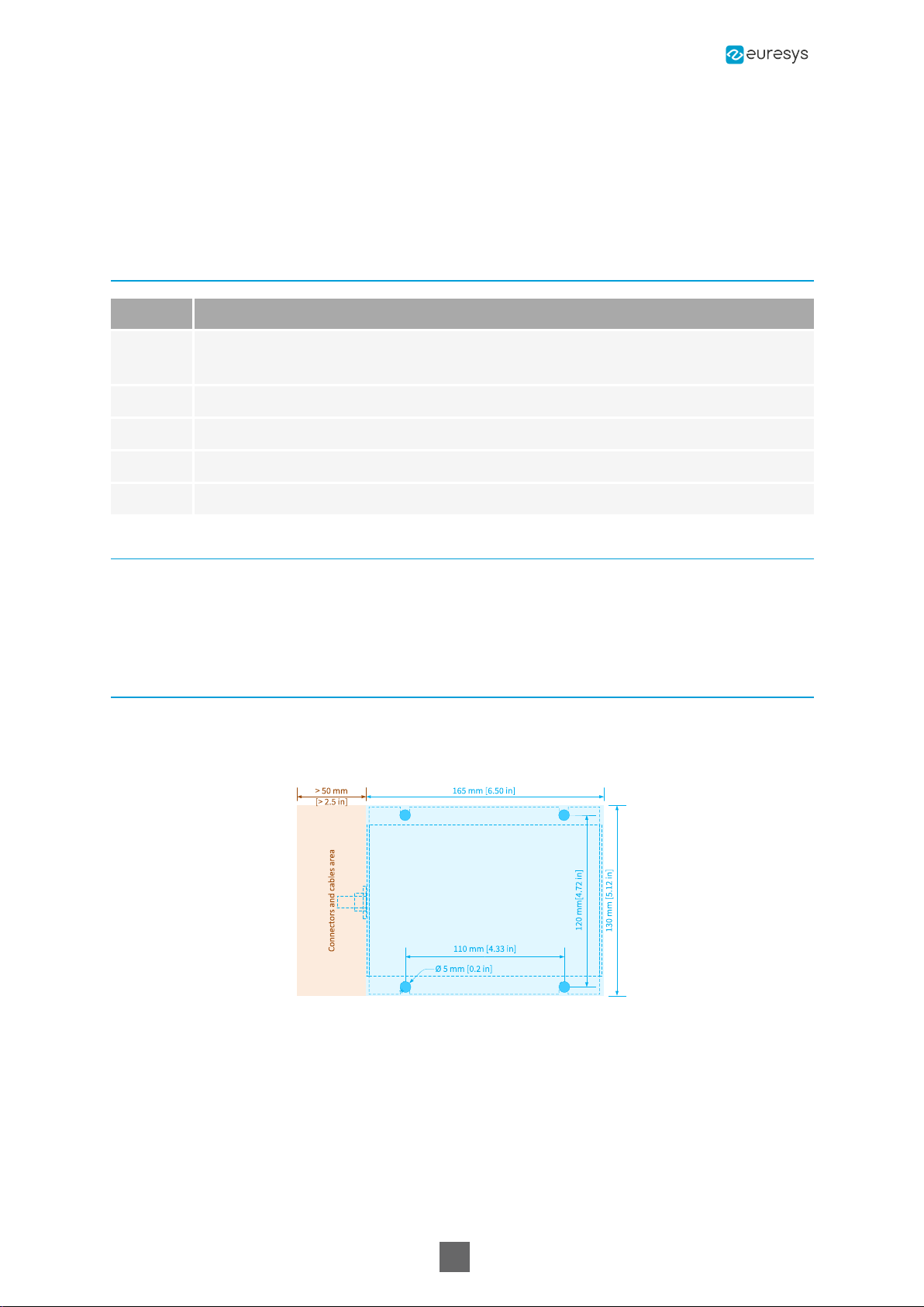
Wall mounting
The out-of-the box product is ready for a desktop or a wall-mount usage. The enclosure is fitted
with 4 oblong holes, 2 on each side, that can be used to attach the product on any flat surface.
Drill and mounting template
Picolo.net Getting Started 2. Installing a Picolo.net

18
2.4. Connectors Location and Markings
Picolo.net HD1 front panel
Picolo.net HD1 rear panel
2.5. Connections
Audio/Video
Audio/Video Inputs
Select one of the following options:
●Connect a HD-SDI or a 3G-SDI audio/video source to the SDI AUDIO/VIDEO IN female
BNCconnector.
●Connect an HDMI HD audio/video source to the HDMI type A (full size) input.
Audio/Video Output
Connect an HDMI HD audio/video sink to the HDMI type A (full size) output.
Picolo.net Getting Started 2. Installing a Picolo.net

19
Analog Audio Input
Using a 3.5mm jack, connect an analog stereo (or mono) line-level audio sources to the AUDIO
IN connector.
3.5 mm stereo jack
Analog Audio Output
Using a 3.5mm jack, connect an analog stereo (or mono) line-level audio sink to the AUDIO OUT
connector.
Network
Connect the device to the local area network by attaching a RJ-45 network cable into the LAN
connector.
USB External Storage
USB for external storage
With a USBtype A (full size) connector, connects a USB storage device to any of the USB
connectors.
Devices exceeding 2.5 Wmust be powered externally.
USB for GPS
With a USBtype A (full size) connector, connects a USB GPS device to any of the USB
connectors.
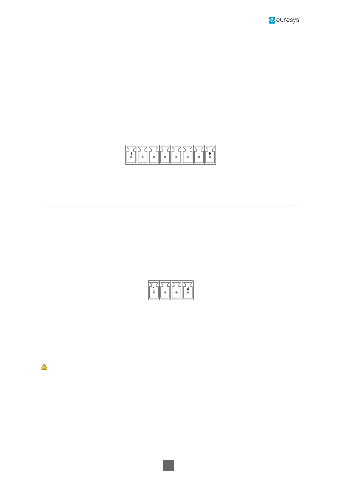
Serial COM
Connect one serial device to the COMconnector via a 8-pin 3.81mm pitch terminal plug using
one of the following wiring options:
●For a full-duplex RS-422 device:
a. Connect the TxD- and the TxD+ output signals respectively to the RxD- (pin 1) and the
RxD+ (pin 2) inputs of the 8-pin terminal plug
b. Connect the RxD- and the RxD+ input signals respectively to the TxD- (pin 3) and the TxD+
(pin 4) outputs of the 8-pin terminal plug
c. Connect the GND signal and/or the cable shield to the GND (pin 5 and/or pin 6) of the 8-pin
terminal plug
●For a half-duplex RS-485 device:
Picolo.net Getting Started 2. Installing a Picolo.net
20
a. Connect the Data- and the Data+ signals respectively to the Rx/TxD- (pin 3) and the
Rx/TxD+ (pin 4) outputs of the COM connector 8-pin terminal plug
b. Connect the GND signal and/or the cable shield to the GND (pin 5 and/or pin 6) of the 8-pin
terminal plug
●For a RS-232 device:
a. Connect the GND signal and/or the cable shield to the GND (pin 5 and/or pin 6) of the 8-pin
terminal plug
b. Connect the Tx output signal to the RxD input (pin 7) of the 8-pin terminal plug
c. Connect the Rx output signal to the TxD output (pin 8) of the COM 8-pin terminal plug
COM connector
General Purpose I/O
Connect one alarm sensor device and/or one relay-driven device to the GPIO connector via a 4-
pin 3.81mm pitch terminal plug:
●To connect one alarm sensor, insert the 2 wires into INA (pin 1) and INB (pin2) of the 4-pin
plug.
●To connect one relay-driven device, insert the 2 wires into OUTA (pin 3) and OUTB (pin4) of
the 4-pin plug.
GPIOconnector
The wiring polarity is irrelevant.
Power Input
Risk of damage to the product
Turn off or disconnect the power source before proceeding.
Connect a 12V DC power source to the POWER IN connector via a 2-pin 3.81 mm pitch terminal
plug:
a. Connect the GNDto the GND input (pin 1) of the 2-pin terminal plug
b. Connect the +12V output to the +12V input (pin 2) of the 2-pin terminal plug
Picolo.net Getting Started 2. Installing a Picolo.net
This manual suits for next models
2
Table of contents
Other Euresys Media Converter manuals


