Euresys Picolo.net HD1 User manual

Picolo.net
Picolo.net HD1
INSTALLATION GUIDE
© EURESYS s.a.2020 - Document D310EN-Installation Guide-Picolo.net_HD1-2.6.9.3032 built on 2020-03-25

1. Disclaimer
EURESYS s.a. shall retain all property rights, title and interest of the documentation of the hardware and the software, and of
the trademarks of EURESYS s.a.
All the names of companies and products mentioned in the documentation may be the trademarks of their respective
owners.
The licensing, use, leasing, loaning, translation, reproduction, copying or modification of the hardware or the software,
brands or documentation of EURESYS s.a. contained in this book, is not allowed without prior notice.
EURESYS s.a. may modify the product specification or change the information given in this documentation at any time, at its
discretion, and without prior notice.
EURESYS s.a. shall not be liable for any loss of or damage to revenues, profits, goodwill, data, information systems or other
special, incidental, indirect, consequential or punitive damages of any kind arising in connection with the use of the
hardware or the software of EURESYS s.a. or resulting of omissions or errors in this documentation.
2. Declarations of Conformity
CE Compliance (EMC Class A)
Notice for Europe
This product is in conformity with the Council Directive 2014/30/EU
This equipment has been tested and found to comply with Class A EN55022/CISPR22 and Class A EN55024/CISPR24.
This product has been tested in a typical class A compliant host system. It is assumed that this product will also achieve
compliance in any class A compliant unit.
To meet EC requirements, shielded cables must be used to connect a peripheral to the card.
FCC Compliance (Class A)
Notice for USA
Compliance Information Statement (Declaration of Conformity Procedure) DoC FCC Part 15
This equipment has been tested and found to comply with the limits for a Class A digital device, pursuant to Part 15 of the
FCC Rules.
These limits are designed to provide reasonable protection against harmful interference in a residential installation or when
the equipment is operated in a commercial environment.
This equipment generates, uses and can radiate radio frequency energy and, if not installed and used in accordance with the
instructions, may cause harmful interference to radio communications. However, there is no guarantee that interference will
not occur in a particular installation.
If this equipment does cause harmful interference to radio or television reception, which can be determined by turning the
equipment off and on, the user is encouraged to try to correct the interference by one or more of the following measures:
●Reorient or relocate the receiving antenna.
●Increase the separation between the equipment and receiver.
●Connect the equipment into an outlet on a circuit different from that to which the receiver is connected.
●Consult the dealer or an experienced radio/TV technician for help.
KC Compliance
Notice for Korea
The following products have been registered under the Clause 3, Article 58-2 of Radio Wave Acts:
Product KC Registration Number
PC1669-DW - Picolo.net HD1 (Desktop/Wall) R-R-EUr-PC1669
PC1669-DR - Picolo.net HD1 (DIN rail) R-R-EUr-PC1669

RoHS Compliance
This product is in conformity with the European Union RoHS 2011/65/EU Directive, that stands for "the
restriction of the use of certain hazardous substances in electrical and electronic equipment".
WEEE
According the European directive 2012/19/EU, the product must be disposed of separately from normal
household waste. It must be recycled according to the local regulations.
3. Installation
Box content
Quantity Items
1 1669-DR Picolo.net HD1 (DIN rail) or 1669-DW Picolo.net HD1 (Desktop/Wall) enclosure
1 8-pin (1x8) 3.81mm pitch terminal plug
1 4-pin (1x4) 3.81mm pitch terminal plug
1 2-pin (1x4) 3.81mm pitch terminal plug
1 Picolo.net HD1 Installation Guide
DIN-rail mounting
The out-of-the box product is ready for installation on a DIN rail.
The DIN rail must be horizontal; two possible orientations are allowed: left facing connectors or right facing connectors.
Wall mounting
The out-of-the box product is ready for a desktop or a wall-mount usage. The enclosure is fitted with 4 oblong holes, 2 on
each side, that can be used to attach the product on any flat surface.
Drill and mounting template

4. Connectors Location and Markings
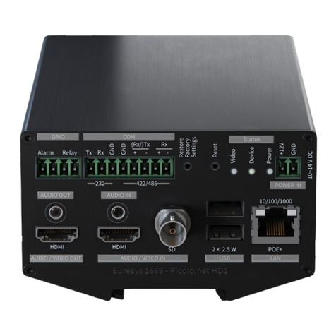
Picolo.net HD1 front panel
Picolo.net HD1 rear panel
5. Connections
Audio/Video
Audio/Video Inputs
Select one of the following options:
●Connect a HD-SDI or a 3G-SDI audio/video source to the SDI AUDIO/VIDEO IN female BNCconnector.
●Connect an HDMI HD audio/video source to the HDMI type A (full size) input.
Audio/Video Output
Connect an HDMI HD audio/video sink to the HDMI type A (full size) output.
Analog Audio Input
Using a 3.5mm jack, connect an analog stereo (or mono) line-level audio sources to the AUDIO IN connector.

3.5 mm stereo jack
Analog Audio Output
Using a 3.5mm jack, connect an analog stereo (or mono) line-level audio sink to the AUDIO OUT connector.
Network
Connect the device to the local area network by attaching a RJ-45 network cable into the LAN connector.
USB External Storage
USB for external storage
With a USBtype A (full size) connector, connects a USB storage device to any of the USB connectors.
Devices exceeding 2.5 Wmust be powered externally.
USB for GPS
With a USBtype A (full size) connector, connects a USB GPS device to any of the USB connectors.
Serial COM
Connect one serial device to the COMconnector via a 8-pin 3.81mm pitch terminal plug using one of the following wiring
options:
●For a full-duplex RS-422 device:
a. Connect the TxD- and the TxD+ output signals respectively to the RxD- (pin 1) and the RxD+ (pin 2) inputs of the 8-
pin terminal plug
b. Connect the RxD- and the RxD+ input signals respectively to the TxD- (pin 3) and the TxD+ (pin 4) outputs of the 8-
pin terminal plug
c. Connect the GND signal and/or the cable shield to the GND (pin 5 and/or pin 6) of the 8-pin terminal plug
●For a half-duplex RS-485 device:
a. Connect the Data- and the Data+ signals respectively to the Rx/TxD- (pin 3) and the Rx/TxD+ (pin 4) outputs of the
COM connector 8-pin terminal plug
b. Connect the GND signal and/or the cable shield to the GND (pin 5 and/or pin 6) of the 8-pin terminal plug
●For a RS-232 device:
a. Connect the GND signal and/or the cable shield to the GND (pin 5 and/or pin 6) of the 8-pin terminal plug
b. Connect the Tx output signal to the RxD input (pin 7) of the 8-pin terminal plug
c. Connect the Rx output signal to the TxD output (pin 8) of the COM 8-pin terminal plug

COM connector
General Purpose I/O
Connect one alarm sensor device and/or one relay-driven device to the GPIO connector via a 4-pin 3.81mm pitch terminal
plug:
●To connect one alarm sensor, insert the 2 wires into INA (pin 1) and INB (pin2) of the 4-pin plug.
●To connect one relay-driven device, insert the 2 wires into OUTA (pin 3) and OUTB (pin4) of the 4-pin plug.
GPIOconnector
The wiring polarity is irrelevant.
Power Input
Risk of damage to the product
Turn off or disconnect the power source before proceeding.
Connect a 12V DC power source to the POWER IN connector via a 2-pin 3.81 mm pitch terminal plug:
a. Connect the GNDto the GND input (pin 1) of the 2-pin terminal plug
b. Connect the +12V output to the +12V input (pin 2) of the 2-pin terminal plug
POWER IN connector
1675 Power Supply for Picolo.net HD1, a 12V DC 40 W universal power block is available as accessory.
Risk of Permanent Damage
Electronic devices can be damaged by applying excessive or incorrectly polarized DC voltages.
Use exclusively 12-24V DC power sources. Check power supply wiring before applying power.
6. Configuration
First Boot
1. Apply power and check if the Power OK green LED turns on.
2. Wait about one minute until the completion of the boot procedure.
3. Check if the Video Present LED indicators of all inputs attached to a valid video source are turned ON.
First Network Session
1. Install the Euresys ONVIF Device Scanner application software utility on a Windows or Linux computer attached to the
same LAN.
2. Ensure that at least one of the following conditions is satisfied on the LAN:

□A DHCP server is active and authorized to deliver an IP address for the MAC address of the LAN interface.
□The computer TCP/IP stack is configured for dynamic IP allocation.
3. Run the Euresys ONVIF Device Scanner utility. At the completion of the scanning process, all discovered ONVIF devices
appear in the discovered ONVIF devices list.
4. Select a device in the list by clicking its [IP] field. The right pane displays the properties of the selected device.
5. Open the device Home page by clicking the [Show] button.
The ONVIF Device Manager application software utility can also be used. ONVIF Device Manager is available on :
http://sourceforge.net/projects/onvifdm/
Manage the media profiles (optional)
The Profile Management page allows the user to view/edit/delete and create media profiles. An auto-setup procedure that
automatically creates media profiles suited to the connected cameras is also available.
Manage the configurations (optional)
The Configuration Management page allows the user to:
●View the video source configurations,
●View and edit the video encoder configurations,
●View and edit the metadata configurations.
Manage the device (optional)
The Device Management page has four tabs:
●The Network tab allows the user to view/edit the device host name, the IP address, the DNS, and the default gateway
settings.
●The Time tab allows the user to view/edit the time and date, and NTP settings.
●The Discovery tab allows the user to enable/disable the device discovery, and to manage the ONVIF scopes.
●The Maintenance tab allows the user to reboot the device, to revert the device to factory settings, and to upload
firmware.
7. Final Check
Video stream from all cameras
Repeat the procedure for all active video sources:
1. Open the Profile Management page.
2. Select a media profile corresponding to the targeted video source, and click the [View/Edit] button.
3. Show the Live Media pane. The video stream is displayed inside a window.
Other manuals for Picolo.net HD1
3
This manual suits for next models
1
Table of contents
Other Euresys Media Converter manuals