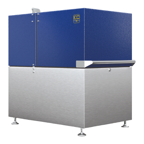
EURO-Jabelmann EURO-Sorter JKS 144/4S Guide

Operating Instructions and
Spare Parts List
For
EURO-Sorter JKS 144/4S
Wilsumer Str. 29
D-49847 Itterbeck
Tel. 0049(0)5948-9339-0
Fax 0049(0)5948-9339-25
info@euro-jabelmann.de
www.euro-jabelmann.de
Ersatzteile:
Tel. 0049(0)5948-9339-26
Fax 0049(0)5948-9339-27

2
Contents Page
Declarations of conformity 3
1. Introduction 4
2. Proper order of use 4
3. Start-up and operation 4
4. Switching elements 6
5. Maintenance and repair 7
6. Guarantee 7
7. Drawings 8
8. Spare parts 9
9. Electric schematic diagram 10

3
EG-Konformitätserklärung nach Maschinenrichtlinie 2006/42/EG Anhang II 1.A
Der Hersteller / Inverkehrbringer
EURO-Jabelmann Veurink GmbH
Wilsumer Straße 29
D-49847 Itterbeck
erklärt hiermit, dass folgendes Produkt
Produktbezeichnung: EURO-Sorter JKS 144/4 ALPHA
Fabrikat: Sortierer
Seriennummer: ____________________________________
Serien-/Typenbezeichnung: JKS 144/4 ALPHA
Beschreibung:
Der Sortierer dient dazu, Knollengewächse, wie Kartoffel oder Zwiebeln in unterschiedliche Größen zu
sortieren.
Allen einschlägigen Bestimmungen der oben genannten Richtlinie sowie den weiteren angewandten
Richtlinien (nachfolgend) - einschließlich deren zum Zeitpunkt der Erklärung geltenden Änderungen -
entspricht.
Folgende harmonisierte Normen wurden angewandt:
EN ISO 12100:2010 Sicherheit von Maschinen - Allgemeine Gestaltungsleitsätze - Risikobeur-
teilung und Risikominderung (ISO 12100:2010)
EN ISO 13857:2008 Sicherheit von Maschinen - Sicherheitsabstände gegen das Erreichen von
Gefährdungsbereichen mit den oberen und unteren Gliedmaßen (ISO
13857:2008)
Name und Anschrift der Person, die bevollmächtigt ist, die technischen Unterlagen zusammenzustellen:
EURO-Jabelmann Veurink GmbH
Herr Bosmann
Wilsumer Straße 29
D-49847 Itterbeck
Itterbeck, _____________________ _______________________________________
(Unterschrift)

4
1. Introduction
1.1 General information
Please read the operating instructions prior to the first start-up of the device. Only a careful ob-
servance of the following regulations and notes guarantees a trouble-free and accident-free applica-
tion and a long operating life.
1.2 Symbols and definitions used in the operating instructions
Caution: Danger of life and risk of injuries! - This symbol indicates dangers for body and
health through tearing and retracting chains.
Caution: Risk of injury! - This symbol denotes risks of injuries.
Caution! This symbol denotes risks for the machine, the complete plant or other values.
This symbol denotes special notes.
2. Proper order of use
The device is solely suitable for the sorting of potatoes and onions.
Any other use is not according to the regulations.
The manufacturer is not liable for damages resulting hereof and the risk is solely born by the user.
Taking notice of the instruction manual and adhering to the operation, maintenance and servicing
regulations form part of the use according to the regulations.
The machines shall only be used, serviced and repaired by personnel, who are familiar herewith and
have been advised of the dangers.
The relevant accident prevention regulations as well all other recognized safety-related, health and
safety and road safety regulations shall be adhered to.
Unauthorized changes of the machine exclude a liability of the manufacturer for the damages result-
ing hereof.

5
Technical data
Transport length: 3.30 m
Width: 1.35 m
Transport height: 1.80 m
Working height: 1.80 -2.10 m
Sifter surface: 1.40 x0.75 m
Weight 950 kg
Approx. performance: 7-9 t/h
Arrangement of sifting: 3 sieves arranged one above the other
Electro motor: 1x 1.1kW FU Controlled 230 volt
1x 0.37kW, 380 volt (sifter cleaning)
Noise reduction: measured 71 dB (A) at the ear of the operating person
while sorting.
3. Start-up and operation
This sorter is a machine wit three screens and therefore suitable for sorting into four sizes, whereas
two sizes can be sorted on an added sorting table. Oversizes and triplets will be lead out of the ma-
chine on the left and hand or right hand side out of the machine.
Before start up the accordance of the power supply with the voltage of the motors has to be
checked.
In order to reach an optimal sorting accuracy the machine is equipped with a continuous speed con-
trol (frequency control) and additional interval drive which means the rotation speed of the crank
shaft changes continuously between 0 and ful rotation speed. This low-maintenance interval drive is
electronically controlled via a timed relay in the control cabinet. The interval of the pause can be
slightly changed by turning the knurl switch on the outside of the control cabinet accordingly. The
relation pause - operation time should lie by about 1:2. Additionally the interval operation can be
switched "on" or "off" via a second switch.
The screen cleaning slide is lead via the middle belt. A good tension of the belt has to be ensured.
The screen cleaning bars should be adjusted until they hit briefly under the screen when in their
highest position.
For changing of the screen the screen cleaning slide has to be driven backwards (to the main bear-
ing). The screens can be taken out on the side after the bolts have been disengaged.
Apart from this main bearing all bearings are maintenance-free. These should be greased app. every
100 hours of operation.
For a long life and faultless operation the machine should be kept as clean as possible.
If during activation of the machine on the left hand side of the control cabinet the red indicator lamp
"rotation direction wrong" illuminates, the rotating field of the power connection is wrong. The ma-
chine does not start up. In order to change the rotating field two phases in the connecting plug
( phase inverter) have to be swapped.
In order to switch on the screen cleaning slide the switch "screen cleaning" has to be switched to
"I".

6
4. Switching elements:
Legend: Impuls Ein / Aus = Impulse On / Off, Drehfeldkontrolle = Rotary field control, Impulszeit
= Impulse period, Reiniger Ein / Aus = Cleaner On / Off, Pausenzeit = Interval period, Drehzahlre-
gelung = Speed control, Not-Aus Taster =
Emergency Off switch, Schloss = Lock, Start Taste = Start switch, Drehzahlregelung Ein / Aus =
Speed control On / Off, Hauptschalter = Main switch

7
5. Maintenance and repair
Do not place your hand into operating machine!
Never open or remove protective devices when the motor is running.
Prior to repair, maintenance and cleaning works, always switch off the motor and remove
the plug from the electrical supply!
Apply a dry cleaning of the machine in regular intervals.
5.1. Lubrication. Adjusting of chains
Regularly lubricate the lubrication points. If necessary, readjust the chains.
Switch off motor, remove power plug and open lateral panelling.
Greasing points are to be greased with standard grease.
If necessary, readjust the chains at the straining screws.
5.2. Repairs
Let repair works be carried out only by trained staff!
6. Guarantee
The warranty for material and processing in accordance with our Terms of Sales and Payments is
taken as agreed. Warranty is excluded in case of:
non proper use,
Non-adherence to the instruction manual, use of non-original spare parts and unauthorized technical
adjustment.
Period of warranty: 6 months after delivery.
Immediately report warranty claims in writing together with complete information, if possible with
the damaged part.

8
7. Drawing
A:
B:

9
8. Spare parts
N°: Designation Number Part n°
1Electro foot-motor I1.1 kW, n=1380 R/rnin.
2V-belt 2mm, continuous
3Pedestal bearing 2RASE 40
4Main bearing, compl. 3W 126-004 (I) PDA 10
5Lifting tarpaulin spring 650mm
long 3W 600-026 (4)
6Wooden spring 1,030mm long 2W 600-006 (4)
7Wooden spring 740 mm long 2W 600-006 (4)
8Wooden spring 790 mm long 4W 600-007 (4)
9Nubbed belt I0 4 x 6500
10
cylindric extension spring with
complete German eyelet 2Da=25 d=5 Lo=200
11 Wheel 10 0-Ro/65
12 Double chainwheel 5/8" x 3/8",
12/44 Z 1W 143-049 (4)
13 Chainwheel 5/8" x 3/8", 40 Z 1W 143-030 (4)
14 Chainwheel 5/8" x 3/8", 12 Z 1W 143-001 (4)
15 Chain (motor – eccentric shaft) 15/8" x 3/8", 61 members,
16 Chain (motor – rope wheel) 15/8" x 3/8",46 members,
1 straight connector
17 Lifting axis 700 mm long 2W 123-018 (3), T 1-2
18 Bearing 2W 123-018 (3), T 3-4
19 Bolt 2W 123-018 (3), T 5
20 Bearing for lifting axis 43003-4- 5 (4)
21 Gear - foot-motor 10,25 kW, n 47 V/min., SK 11
-71 S/4
22 Rubber plate for sifter cleaning, 4N 6005-1-17-3
750 x 780

10
9. Electric schematic diagram

11

12

13

14
Table of contents
Popular Industrial Equipment manuals by other brands
ABB
ABB UniGear ZS2 UniSafe 36 Installation, Operation and Maintainance Instructions

Endress+Hauser
Endress+Hauser Stamoclean CAT430 operating instructions
Pentair
Pentair AVID LP R2 Installation and operating instructions
AAF
AAF AmericanAirFilter K Installation, operation and maintenance instructions

GL
GL P103 Assembly & fitting instructions

PushCorp
PushCorp AFD1000 Series manual
