Europlex SigNET200 Series User manual
ELAB 1543
SigNET 200/300 Series
User Guide

SigNET 200/300 User Guide
2 ELAB 1543
COPYRIGHT NOTICE
Copyright © 2008 Europlex Technologies Ltd (hereby referred to as Europlex). All rights reserved. No part of this publication
may be reproduced, transmitted, stored in a retrieval system, or translated into any language or computer language in any
form or by any means electronic, mechanical, magnetic, optical, chemical, manual, or otherwise without the prior written
permission of Europlex.
Disclaimer: Europlex make no representations or warranties with respect to the contents hereof and specifically disclaim any
implied warranties of merchantability or fitness for any particular purpose. Further Europlex reserve the right to revise this
publication and to make changes from time to time in the contents hereof without the obligation of Europlex to notify any
person of any such revision.
All products or services mentioned in this manual are covered by the trademarks, service marks, or product names as
designated by the companies who market those products.
ELAB1543 SigNET 200/300 User Guide, Issue 04, May 2008
When changing or installing expanders on the SigNET 200/300 system always ensure that all
anti-static precautions are adhered to while handling connectors, wires, terminals and PCBs.
Europlex Technologies [IRL] Ltd.
Clonshaugh Business and Technology Park,
Clonshaugh,
Dublin 17,
Ireland.
Tel: +353 (0) 1 2500500
Fax: +353 (0) 1 2500592
Europlex Technologies (UK) Limited
Innovation Centre,
Cranfield University Technology Park,
University Way, Cranfield,
Bedfordshire, MK43 0BT,
United Kingdom.
Tel. +44 (0) 8700 600 140
Fax. +44 (0) 8453 307 240
E-Mail: [email protected]
Company Web Site address: www.europlex.ie
Technical Support: tech@europlex.ie
Warning: While this system is an advanced design integrated security system, it does not offer guaranteed protection
against burglary, fire or other emergency. Any alarm system, whether commercial or domestic, is subject to
compromise or failure to warn for a variety of reasons.
Therefore, good installation practices, thorough testing, and regular maintenance by the installation company and
frequent testing by the user are essential to ensure continuous satisfactory operation of the system. It is recommended
that the installation company offer a maintenance program and instruct the user with the correct procedure for use and
testing of the system.

SigNET 200/300 User Guide
ELAB 1543 3
Table of Contents
1. INTRODUCING THE SIGNET 200/300 SYSTEM...........................................................................................................4
2. USING THE KEYPAD.........................................................................................................................................................4
2.1 USING THE KEYPAD INTERFACE.......................................................................................................................................5
3. SETTING, UNSETTING, AND RESTORING THE SYSTEM........................................................................................6
3.1 SETTING THE SYSTEM:FULLSET ...................................................................................................................................6
3.2 SETTING THE SYSTEM:PARTSET A................................................................................................................................6
3.3 SETTING THE SYSTEM:PARTSET B................................................................................................................................6
3.4 FAILING TO SET THE SYSTEM...........................................................................................................................................7
3.5 FORCE SETTING THE SYSTEM...........................................................................................................................................7
3.6 UNSETTING THE SYSTEM..................................................................................................................................................7
3.7 RESTORING AN ALARM ACTIVATION (ALERT).................................................................................................................7
3.8 CODED RESTORE..............................................................................................................................................................8
3.9 USING 868MHZ WIRELESS FOB.......................................................................................................................................8
3.10 USING A PORTABLE ACE.................................................................................................................................................8
3.11 USING X10 FEATURES......................................................................................................................................................9
4. USER MENU OPTIONS....................................................................................................................................................10
4.1 INHIBITING A ZONE ........................................................................................................................................................10
4.2 ISOLATING A ZONE OR FAULT ........................................................................................................................................10
4.3 SET DATE/TIME .............................................................................................................................................................10
4.4 PERFORM TESTS.............................................................................................................................................................11
4.5 VIEWING THE EVENT LOG..............................................................................................................................................11
4.6 ENABLING THE CHIME FUNCTION ..................................................................................................................................11
4.7 CREATING SYSTEM USERS .............................................................................................................................................11
4.8 CHANGING A USER CODE...............................................................................................................................................12
4.9 USING SMS....................................................................................................................................................................12
4.10 ALLOWING ENGINEER/MANUFACTURER ACCESS ..........................................................................................................15
APPENDIX A: STANDARD USER SETTINGS .....................................................................................................................16
APPENDIX B: USER CONFIGURATION AND TEST OPTIONS ......................................................................................17
APPENDIX C: ZONE CHART .................................................................................................................................................18

SigNET 200/300 User Guide
4 ELAB 1543
1. Introducing the SigNET 200/300 System
The SigNET 200/300 system must be installed by a qualified installation engineer. When the installation has been
completed, the engineer provides users with passwords to set or unset and configure the system as required.
2. Using the Keypad
The SigNET Keypad is a wall-mounted programming interface unit that allows users to enter User Programming
menus (password protected), and to perform operational procedures (arm/disarm) on the system. The Keypad unit
includes an integral front tamper switch and has a 2 line x 16 character display. Three LEDs provide information on
AC power, system alerts, and communications status. The Keypad features easy-to-use navigation to assist in
locating required programming options, and has two context sensitive soft keys (left and right) for selecting the
required menu or program setting.
The SigNET Keypad may be factory fitted with a Portable ACE (PACE) proximity device reader and/or a wireless
module for the enrolment of wireless sensors.
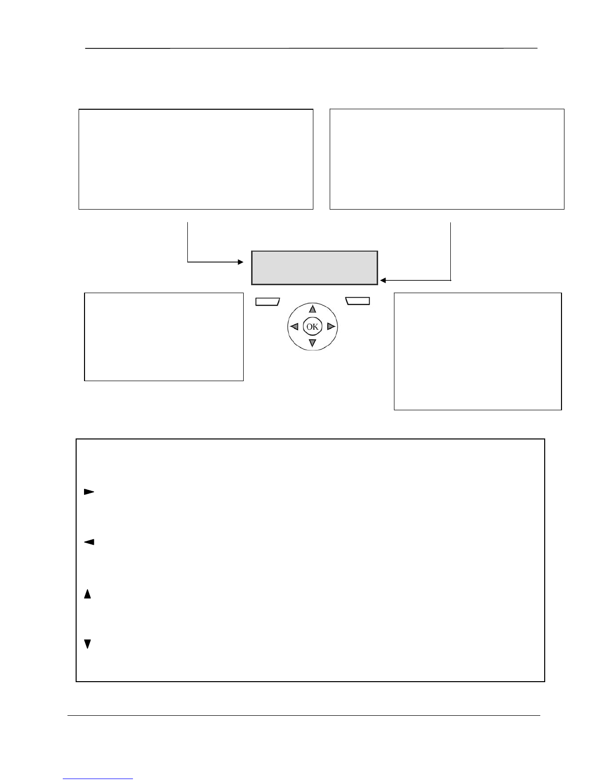
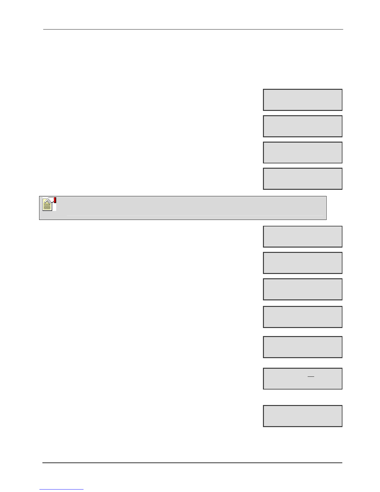
Figure 1 – SigNET Keypad
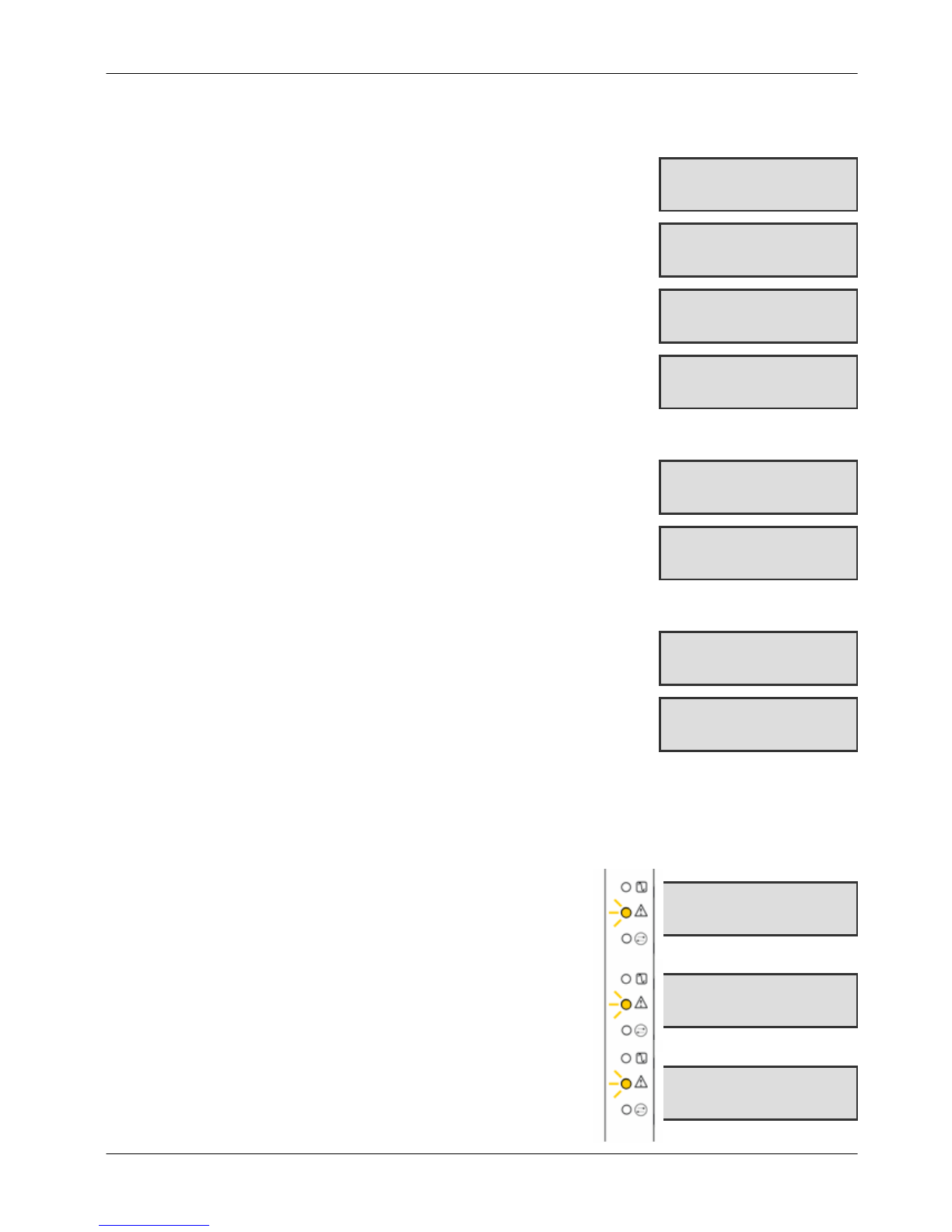
Table 1 – LED Status Indicators
LED Description
AC Mains LED
(green) Indicates presence or failure of the Mains supply
FLASHING: AC Mains fault detected
STEADY: AC Mains OK
System Alert
(yellow) Indicates a system alert
FLASHING: System Alert detected; display indicates the location and nature of the alert. If the
system is SET, no indication of system alerts is given.
OFF: No alert detected
Comms LED
(red) Indicates status of the E-BUS communications when in FULL ENGINEER programming
Programming Keys
1 x multi-functional navigation key
2 x context sensitive programming
keys (left and right)
01 MAY 08 17:00
A
C Mains LED
System Alert LED
Comms LED
Keypad
12 x alphanumeric
keys for numeric
and text data entr
y
Portable ACE
Receiver Area
Licence
Details
Installer Contact
Installer Name
Installation Date
Pull-down Information Tab
The installer contact and licence
details are located on the pull
down information tab at the rear
of the unit
SigNET 200/300 User Guide
ELAB 1543 5
2.1 Using the Keypad Interface
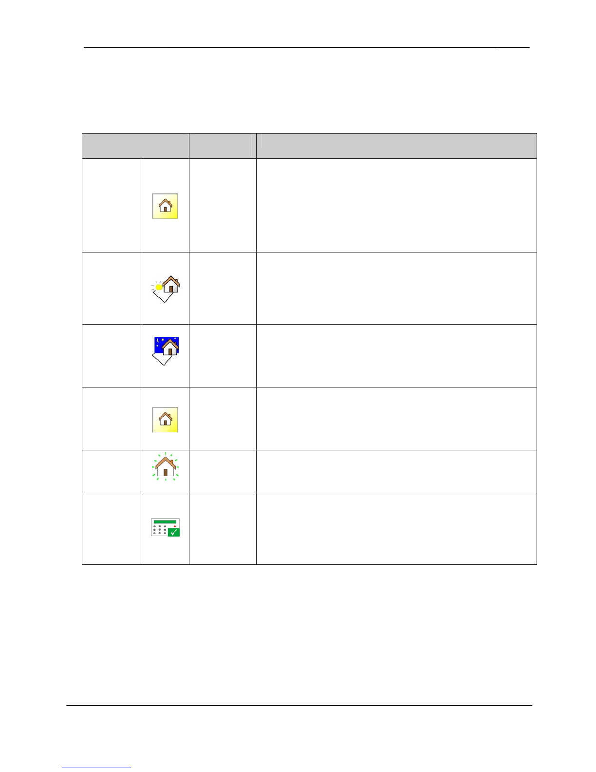
Figure 2 – Keypad Interface
MULTI-FUNCTION NAVIGATION KEY
OK The OK button acts as a SELECT key for the menu option displayed on the top line and also as an
ENTER/SAVE key for data display on the top line.
In Programming Mode, the right arrow key advances the user through the menus in the same way as pressing
the SELECT option (right soft key).
In data entry mode, press this key to move the cursor one position to the right.
In Programming Mode, the left arrow key returns the user to the previous menu level. Pressing this key when
in the top menu level exits the user from programming.
In data entry mode, press this key to move the cursor one position to the left.
In Programming Mode, the up arrow key moves the user to a previous programming option in the same menu
level. Continually press this key to scroll through all programming options available on the current menu level.
In alphanumeric mode, press this key over a lower case character to change the character to upper case.
In Programming Mode, the down arrow key moves the user to the next programming option in the same menu
level. Continually press this key to scroll through all programming options available on the current menu level.
In alphanumeric mode, press this key over an upper case character to change the character to lower case.
TOP LINE OF DISPLAY
In the normal state, displays the current date and time.
In Programming Mode, this line displays one of the
following:
→The programming feature to be selected
→The current setting of the selected feature
During an alert condition, this line displays the nature of the
current alert
BOTTOM LINE OF DISPLAY
In the normal state, this line is blank.
In Programming Mode, this line displays options available
to the user. These options align over the left and right soft
keys for selection as required.
RIGHT SOFT KEY
This key is used to select the option
presented on the right side of the bottom
line display.
Possible values are:
→SELECT to select the option
displayed on the top line
→ENTER to enter the data displayed on
the top line
→SAVE to save a setting
LEFT SOFT KEY
This key is used to select the option
presented on the left side of the
bottom line display.
Possible values are:
→EXIT to exit programming
→BACK to return to previous menu
SETUP SYSTEM
EXIT SELECT

SigNET 200/300 User Guide
6 ELAB 1543
3. Setting, Unsetting, and Restoring the System
The following functions are available to users by entering a user code; these
functions do not require menu navigation on the Keypad. User codes
comprise 4, 5, or 6 digits, depending upon the programming grade of the
system.
A user’s permission rights, i.e. ability to see menus and options available on
the SigNET 200/300 system, are programmed by the installation engineer. If
users cannot see options described in this manual, they do not have rights to
access such functionality.
When a code is entered, the digits display as asterixes and the left function
key displays the QUIT option. This is for security reasons, so codes are not
visible when entered.
After entering a code, the following options are presented: FULLSET,
PARTSET A, PARTSET B, MENUS. Scroll these options by using the
up/down arrow keys. An ellipsis (…) on accompanying graphics denotes
when there is a choice of menu selection by scrolling.
3.1 Setting the System: FULLSET
The FULLSET option provides the following functionality:
•Full protection to a building (opening of alarm zones activates alarm)
•Opening of entry/exit zones starts the entry timer. If the alarm is not
unset before the entry timer expires, the alarm is activated
To select the FULLSET option, enter a valid user code, and press SELECT
(right soft key). The second line displays the exit time and the buzzer sounds
to indicate that the user should exit the building. When the system has been
fully set, the LCD displays FULLSET on the bottom line for approximately 10
seconds.
If the alarm fails to set, see Section 3.4, Failing to Set the System.
3.2 Setting the System: PARTSET A
The PARTSET A option provides the following functionality:
•Perimeter protection to a building while allowing free movement
through the exit and access areas
•Exclusion of EXCLUDE A zones from protection
•Instant activation of alarm on selection of mode; by default there are
no exit times associated with PARTSET A
To select PARTSET A, enter a valid user code, scroll to the PARTSET A
option and press SELECT (right soft key).
If the alarm fails to set, see Section 3.4, Failing to Set the System.
3.3 Setting the System: PARTSET B
The PARTSET B option provides the following functionality:
•Perimeter protection to a building while allowing free movement
through the exit and access areas
•Exclusion of EXCLUDE B zones from protection
•Instant activation of alarm on selection of mode; by default there are
no exit times associated with PARTSET B
To select PARTSET B, enter a valid user code, scroll to the PARTSET B
option and press SELECT (right soft key).
Note
Partset A and Partset B configuration modes are dependent upon how the system has been
programmed.
…FULLSET?...
EXIT SELECT
…PARTSET A?...
EXIT SELECT
…PARTSET B?...
EXIT SELECT
…MENUS…
EXIT SELECT
…FULLSET?...
EXIT SELECT
18/04/2008 12:30
SETTING 45 SECONDS
18/04/2008 12:30
SYSTEM FULLSET
…PARTSET A?...
EXIT SELECT
18/04/2008 12:54
PARTSET A SET
…PARTSET B?...
EXIT SELECT
18/04/2008 12:55
PARTSET B SET
SigNET 200/300 User Guide
ELAB 1543 7
3.4 Failing to Set the System
The system fails to set if there is an open or fault condition detected on an alarm zone when the FULLSET or
PARTSET A/B option is selected. The Keypad displays the zone number and
description.
To set the system, locate the zone and close or fix the fault. Repeat the FULLSET
or PARTSET A/B operation.
3.5 Force Setting the System
The system can be forced to set while an alarm zone is still open. This operation
inhibits the open zone and sets the system as normal.
If a user has the right to FORCE SET the system and an alarm zone is open,
when the FULLSET or PARTSET option is selected, the Keypad buzzer beeps
and the first line of the display indicates the open zone. The user is presented with
the options to QUIT (left soft key) or FORCE (right soft key).
QUIT: Selecting this option aborts the attempt to set the system and returns the
user to User Programming.
FORCE: Selecting this option inhibits the open zone and forces the system to set.
3.6 Unsetting the System
To UNSET a system:
1. Enter a valid user code. The Keypad displays a prompt to unset the
system.
2. To UNSET the system, press SELECT (right soft key). The Keypad
display indicates that the system is unset on the bottom line of the
display for approximately five seconds. After this time has elapsed, the
bottom line is cleared.
3. If the alarm has been activated, entering the user code silences all
bells and strobes and the message PANEL DISARMED displays on the
Keypad for approximately five seconds.
4. The source of the alarm condition displays on the Keypad and the Alert
LED flashes. The Keypad continues to display the alert until the alert is
restored.
3.7 Restoring an Alarm Activation (Alert)
Alert conditions on the SigNET are indicated on the Keypad by a flashing yellow Alert LED and by activation
of the buzzer. The Keypad indicates the location and nature of the alert condition. The ability of a user to
restore alerts depends on the security grade setting of the system (in accordance with standards [1]). An alert
condition can only be restored once the fault or zone that caused the alert has been physically reset to its
normal operating state; e.g. an open zone has been closed again or a severed E-BUS connection re-
established.
Users may be restricted from using the Restore feature if an Engineer
chooses not to select ‘Restore’ within the User Rights menu for select
users. Users who cannot restore an alert receive fault messages on the
Keypad until the zone or fault condition is either inhibited or isolated.
Alarm conditions on the SigNET 200/300 are indicated on the Keypad
by a flashing yellow Alert LED (see Section 2, Using the Keypad) and
by activation of the buzzer. The Keypad displays the location and
nature of the alert condition.
To restore an alert condition triggered by a zone opening:
1. Locate the open zone (displays on the Keypad) and restore the
alarm sensor to its normal state by closing the door or window.
2. Enter a valid user code and select the RESTORE option (right
soft key). The zone causing the alert displays on the top line.
ZONE 1 OPEN
QUIT FORCE
…FORCED SET?...
BACK SELECT
18/04/2008 12:30
SETTING 45 SECONDS
18/04/2008 12:30
SYSTEM FULLSET
…UNSET?...
EXIT SELECT
SYSTEM UNSET
PANEL DISARMED
ALARM ZONE 2
FIRST ZONE
ALARM ZONE 2
Sitting Room
Sitting Room
QUIT RESTORE
ALL ALERTS
RESTORED

SigNET 200/300 User Guide
8 ELAB 1543
3. Press the right menu key to restore the alert. The message ALL ALERTS RESTORED displays and
the flashing Alert LED turns off.
For system or communications type alert conditions (Mains failure or E-BUS disconnect), locate the source of
the alert condition and check that all wires and cables are properly connected.
For a tamper alert, ensure the lids on all enclosures and devices are correctly closed. If the physical fault
cannot be restored to its normal operating state, contact the installation engineer. The alarm system still
operates by either inhibiting or isolating the fault condition.
3.8 Coded Restore
The coded restore option is only available if the Security Grade of the system is set to Grade 3 or Engineer
Configure. It provides the user with the ability to restore alert conditions that would normally only be
available to the installation engineer. To provide the user with this ability, it is necessary to protect this
feature with a code.
To perform a coded restore on the system:
1. Ensure that the zone or fault that caused the alert condition has been physically restored to
its normal operating state.
2. Contact the installer or the alarm receiving centre (ARC) before entering user programming
and selecting the coded restore feature in the menus option. (Contact details should be
available from the drop down label beneath the Keypad.)
3. Press SELECT on the Coded Restore option. A 6-digit reset code displays on the top line.
4. Provide 6-digit code to installer/ARC.
5. Receive newly generated code from installer/ARC.
6. Enter new code at the AUTH CODE prompt.
7. Press SELECT.
The message SYSTEM RESTORED displays on the top line of the display.
3.9 Using 868MHz Wireless Fob
If an 868MHz wireless receiver module (Fob) is installed and configured on the Keypad or Controller and the
user profile is configured for device and respective settings, the SigNET system enables functionality using a
868 MHz wireless fob. An authorised installation engineer configures the device and its settings, and users
are instructed for activation of the device for the following commands:
•Set/Unset
•Partset
•Clear Alerts/Restore
•X10 Functionality
3.10 Using a Portable ACE
If a PACE reader is installed and configured on the SigNET Keypad, it is functional only with users of PACE-
configured profiles.
If a Limited User’s profile is configured for such device and functionality, once presented within 1cm of the
Keypad’s receiver area, the PACE enables setting and unsetting denoted by the usual set/unset beeps.
Note
An Alert condition only displays on the Keypad when the system is UNSET. If the system is SET
when an alert condition occurs, the Keypad gives no indication of that alert condition until such
time as the system is UNSET.
Note
The coded restore feature can only be operated from the Keypad. It is not accessible from the
browser.
Note
Force setting with the RF fob: It is NOT possible to forceset the system with an RF fob even if the
user assigned to the fob has the ability to forceset. Force setting is only possible at the Keypad.
SigNET 200/300 User Guide
ELAB 1543 9
If Manager and/or Standard Users’ profiles are configured for such device and functionality, access to keypad
is allowed using the PACE. Presentation of the device within 1cm of the Keypad’s receiver area logs in the
user and prompts menu options.
For additional security measures, engineers have the option to set the PACE configurations to PIN and PACE.
This prompts and requires user code following presentation of the PACE.
3.11 Using X10 Features
X10 is a technology that allows peripheral devices, such as lights, heaters, or appliances, to be controlled by the
system and system events can be used to trigger outputs on the X10 devices. For example, a hall light could be
configured to turn on when the front door of the house is opened. Alternatively, the function can be controlled directly
at the Keypad.
X10 settings are programmed by the installation engineer and users are informed of the settings and the
corresponding keys on the Keypad or the appropriate buttons of a configured 868MHz Wireless Fob.
On the keypad, turn an X10 feature on by pressing the hash (#) key and the feature number. The corresponding
device turns on. To turn an X10 feature off, repeat the same keystrokes. The corresponding device turns off. The
installation engineer can fill in the following table for quick reference.
Table 2 – X10 Codes and Descriptions
Code # Description
#0
#1
#2
#3
#4
#5
#6
#7
#8
#9
Note
X10 uses uni-directional communication and should not be used for critical devices because
system interference can prevent the device from responding to the command.
SigNET 200/300 User Guide
10 ELAB 1543
4. User Menu Options
The following functions are available to users under MENUS on the Keypad.
In navigation mode following input of user code, the user selects one of a number of pre-defined programming
options from a list. Pressing the up/down arrow keys scrolls the list of options available for selection. An ellipsis (…)
on accompanying graphics denotes when there is a choice of menu selection by
scrolling.
4.1 Inhibiting a Zone
Zones on the system can be manually inhibited from the Keypad. Inhibiting a
zone removes that zone from the system, silently disregarded, for one alarm set
period only.
1. Press SELECT the INHIBIT option on the Keypad.
2. Scroll to the ZONES option and press SELECT (right soft key).
3. Scroll and select the required zone and toggle the setting from NOT
INHIBITED to INHIBITED using the up/down arrow keys.
4. Press SELECT (right soft key) to exit user programming.
4.2 Isolating a Zone or Fault
Zones or faults on the system can be manually isolated from the Keypad.
Isolation allows a zone to be removed from the system, silently disregarded, until
it is set for de-isolation by the user.
To isolate a zone:
1. Scroll to the ISOLATE option and press SELECT (right soft key).
2. Scroll to the ZONES option and press SELECT (right soft key).
3. A list of zones on the system displays. Select the required zone and
toggle the setting from NOT ISOLATED to ISOLATED using the up/down
arrow keys.
4. Press SELECT (right soft key) to exit User Programming.
4.3 Set Date/Time
The date and time can be manually entered on the system. The time and date
information displays on the Keypad to be used with time-related programming
features.
To program the Date and Time:
1. Scroll to the SET DATE/TIME option and press SELECT (right soft key). The
date displays on the top line.
2. To enter a new date, press the required numeric keys. To move the cursor to
the left and right, press the left and right arrow keys. Press ENTER (right soft
key) to save the new date.
3. To enter a new time, press the required numeric keys. To move the cursor to
the left and right, press the left and right arrow keys. Press ENTER (right soft
key) to save the new time.
Note
Only the Alarm, Exit/Entry, Fire Exit and Line Zone types can be inhibited on the SigNET system.
All other zone types are not displayed in the inhibit menus.
…INHIBIT…
EXIT SELECT
…ZONES…
BACK SELECT
…INHIBIITED…
BACK SELECT
…ZONE1…
BACK SELECT
…ISOLATE…
EXIT SELECT
…ZONES…
BACK SELECT
…ISOLATED…
BACK SELECT
…ZONE1…
BACK SELECT
…SET DATE/TIME…
EXIT SELECT
DATE 18/04/2008
BACK ENTER
UPDATED

SigNET 200/300 User Guide
ELAB 1543 11
4.4 Perform Tests
Tests can be performed on the system to determine if bells, buzzers, and other
audible devices operate correctly.
To perform a test on the system:
1. Scroll to the TEST option and press SELECT (right soft key).
2. Scroll and select BELL TEST, WALK TEST, or AUDIBLE OPTIONS.
3. When BELL TEST is selected, users may test each device by pressing
NEXT for external bells, strobe, internal bells, or buzzer. The device
sounds for each to verify it is operating correctly.
4. When WALK TEST is selected, users can test the operation of each alarm
device by activating the device and listening for audible beeps at the
Keypad.
4.5 Viewing the Event Log
The most recent events on the system can be viewed by selecting the EVENT LOG
option. The most recent events display on the bottom line with previous events
displaying for one second in turn.
To view the event log on the Keypad:
1. Scroll to the EVENT LOG option and press SELECT (right soft key).
The Keypad displays the recent events on the system on the bottom line display
for one second in turn.
2. To view an event from a particular date, enter the date with the numeric
keys.
4.6 Enabling the Chime Function
The chime function can be enabled or disabled on all zones where the chime has
been programmed as an audible alert feature.
To enable or disable the chime function:
1. Scroll to the CHIME option and press SELECT (right soft key).
2. Toggle between enable or disable for the chime function.
4.7 Creating System Users
In order to create a user for the system, the creator must be a Manager user type.
To create a user:
1. Scroll to the USERS option and press SELECT.
2. Scroll to ADD and press SELECT.
The system generates and displays next available user name.
3. Press SELECT for the default name and number, or enter a customized user
name and press SELECT.
4. There are three types of users available: STANDARD USER, LIMITED USER,
or MANAGER. Scroll to the preferred type and press SELECT. Note: user
profiles may be changed at any time.
The system generates a default code for each new user. To change this code,
overwrite the digits shown in the initial digits field.
5. Press SELECT to accept or enter a new user code and press SELECT.
The Keypad confirms that the new user has been created.
…TEST…
EXIT SELECT
…BELL TEST…
BACK SELECT
EXT BELL
BACK NEXT
…EVENT LOG…
EXIT SELECT
21 Apr 08 13:47
WALKTEST BY USER
DATE 18/04/2008
BACK ENTER
…CHIME…
EXIT SELECT
…ENABLED…
BACK SELECT
…USERS…
EXIT SELECT
…ADD…
BACK SELECT
…USER1…
BACK SELECT
…STANDARD USER…
BACK SELECT
CODE 1234
BACK ENTER
USER1 CREATED

SigNET 200/300 User Guide
12 ELAB 1543
4.8 Changing a User Code
If users have the right to change their user code, this can be done through the
Keypad.
Note, if the system is set for 5-digit user codes, a new 5-digit code must be entered.
The system will not accept a code with fewer numbers than it is set to receive.
To change a user code:
1. Scroll to CHANGE CODE and press SELECT (right soft key).
A randomly generated user code appears.
2. Select new code, if acceptable. Or overwrite by entering the new user code and
press ENTER (right soft key).
3. Confirm the new code, press SAVE (right soft key).
4. Press BACK (left soft key) to return to the previous screen to amend the code.
During the process if the display times out, the old code remains valid.
4.9 Using SMS
SigNET systems with modems and appropriate configuration, allow SMS
messaging. To use SMS, each user must have the appropriate user profile
rights. Notification of the following events can be sent to users as SMS
messages:
• Alarm Activation
• Confirmed Alarms
• Fault and Tamper
• Arming and Disarming (Mode Change)
• Inhibit and Isolate
• All other types of events
4.9.1 SMS Events
To receive Event notifications, SMS setup must have the phone number; the
number must be enabled for SMS; and the Events must be toggled for SMS
Event notification.
Add the phone number for SMS use:
1. Scroll to the SMS EVENTS option and press SELECT. The following
configuration options are available:
2. Add by providing phone number for receipt of event notification
(Requires three-digit country code prefix)
Edit phone number as needed. (Within this level is also enabling SMS
and selecting Reported Events.) Delete: Remove phone number as
needed
3. Press BACK to exit the SMS EVENTS menu.
Each user may set a maximum of five phone numbers for SMS receipt.
Note
Where User Duress feature is enabled, consecutive user codes (i.e. 2906, 2907) are not
permitted, as entering this code from the Keypad would activate a user duress event.
…CHANGE CODE…
EXIT SELECT
CODE 4740
BACK SELECT
…SMS EVENTS…
EXIT SELECT
…ADD…
EXIT SELECT
SMS NUMBER
353
BACK ENTER
UPDATED
UPDATED

SigNET 200/300 User Guide
ELAB 1543 13
Enable phone number for SMS [receipt] within SMS Events menu:
1. Scroll to the SMS EVENTS option and press SELECT.
2. Select EDIT.
3. Using the up/down arrow keys, scroll to the appropriate registered number
and press SELECT.
4. Scroll to ENABLE NUMBER and press SELECT.
5. Press SELECT for ENABLED [Alternatively, press SELECT for DISABLED.]
6. Press BACK to exit the SMS EVENTS menu.
The keypad displays UPDATED once the setting has been saved.
Select Events for SMS notification within SMS Events menu:
1. Scroll to the SMS EVENTS option and press SELECT.
2. Select EDIT. Using the up/down arrow keys, scroll to the appropriate
registered number and press SELECT.
3. Using the up/down arrow keys, scroll to the REPORTED EVENTS and press
SELECT.
4. Scroll and toggle ENABLED for each Event notification desired.
Events display preceded by an asterisk.
5. Press BACK to exit the SMS EVENTS menu.
4.9.2 SMS Control
Depending on the SMS authentication configured by the installation engineer,
the user’s mode of SMS may vary.
If the system SMS Authentication is set to the SMS PIN Code or Caller ID, it
is necessary to set up SMS Control:
1. Scroll to the SMS CONTROL option and press SELECT. The following
configuration options are available:
SMS CALLER ID: Provide phone number (Requires three-digit country
code prefix)
SMS PIN CODE: Provide pin number
Delete: Remove phone number as needed
2. Press BACK to exit the SMS SETUP menu.
For a complete list of SMS Commands, refer to Table 3.
Note
Beyond User Type, Engineer settings allow specific rights for functionality to be granted to each user. If a
function explained herein does not appear on User keypad menus, the user does not have permission for
that functionality. Consult with authorised installation Engineer for appropriate rights and settings.
…SMS EVENTS…
EXIT SELECT
…EDIT…
EXIT SELECT
…353123123…
BACK SELECT
ENABLE NUMBER
BACK SELECT
…SMS EVENTS…
EXIT SELECT
…EDIT…
EXIT SELECT
…353123123…
BACK SELECT
…REPORTED EVENTS…
BACK SELECT
…ALARMS…
BACK SELECT
…SMS CONTROL…
EXIT SELECT
…SMS CALLER ID…
EXIT SELECT

SigNET 200/300 User Guide
14 ELAB 1543
4.9.3 SMS Commands
Once the SMS setup and configuration is complete, SMS features may be activated. Commands, depending
on SMS configuration are sent using a code or caller ID. The type of code depends on the system SMS
Authentication. An installation Engineer provides the appropriate setting and instructions for use.
The table below provides all available SMS commands. Subsequent action and response are also provided.
SMS Commands are sent as texts to the phone number of the SIM card on the controller. (Available with
GSM modems only.)
For commands using code, the format of the text is the code followed by either a space or a full stop. Where
**** is the code and “command” is the command: ****.command or **** command.
For example, the command “HELP” is this text: **** HELP or ****.HELP
Table 3
COMMANDS (**** = code)
Using Code Using Caller ID Action Response
**** HELP
****.HELP
HELP All available commands
displayed
All available commands
**** FSET
****.FSET
FSET Fullset Alarm Time/date of system set. If
applicable, responds with open
zones/forceset zones
**** USET
****.USET
USET Unset Alarm System Unset
**** SSTA
****.SSTA
SSTA Status displayed Status of system and applicable
areas
**** LOG
****.LOG
Up to 10 recent events
displayed
Recent events
**** ENG.ON
****.ENG.ON
ENG.ON Enable Engineer access Engineer status
**** ENG.OFF
****.ENG.OFF
ENG.OFF Disable Engineer access Engineer status
**** MANA.ON
****.MANA.ON
Enable Manufacturer access Manufacturer status
**** MAN.OFF
****.MAN.OFF
Disable Manufacturer access Manufacturer status

SigNET 200/300 User Guide
ELAB 1543 15
4.10 Allowing Engineer/Manufacturer Access
When engineer or manufacturer access has been allowed, the Keypad displays
the text ENGINEER ENABLE or MANUFACT ENABLE. Once access has been
granted, the user cannot access the system until the engineer has logged off.
To allow engineer access:
1. Scroll to the GRANT ACCESS option and press SELECT (right soft
key).
2. Select the ALLOW ENGINEER option (right soft key) and select
ENABLED.
To disallow engineer/manufacturer access, follow the same path and
toggle to DISABLED and press SELECT (right soft key).
Note
Additional commands are available for X-10 functionality from the qualified installation Engineer if
the system is configured for such use.
…GRANT ACCESS…
EXIT SELECT
UPDATED
EXIT SELECT
…ALLOW ENGINEER…
EXIT SELECT
…ENABLE…
EXIT SELECT
SigNET 200/300 User Guide
16 ELAB 1543
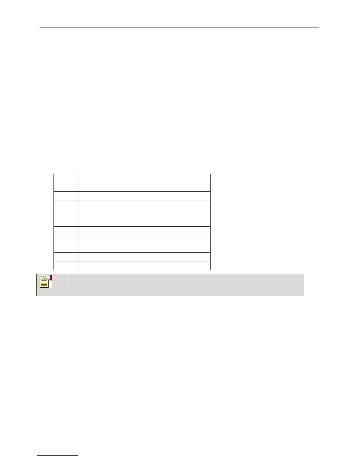
Appendix A: Standard User Settings
The operational features of the SigNET 200/300 system are described below. The installation engineer informs
users of their user rights assigned to each user profile. Depending on how the system has been programmed, users
may have rights to all or some of these features.
Operation User Profile
Default Description
FULLSET
Limited
Standard
Manager
The FULLSET operation fully sets the alarm system and provides full
protection to a building (opening of any alarm zones activates the alarm).
On selecting FULLSET, the buzzer sounds and the Keypad display
counts down the exit time period. Exit the building before this time period
has expired.
When the exit time period has expired, the system is set and opening of
entry/exit zones starts the entry timer. If the system is not Unset before
the entry timer expires, the alarm is activated.
To perform a FULLSET, see Section 3.1.
PARTSET A
Standard
Manager
The PARTSET A option provides perimeter protection to a building while
allowing free movement through the exit and access areas.
Zones that have been classified as EXCLUDE A remain unprotected in
this mode. By default, there is no exit time; the system sets instantly on
selection of this mode. An exit timer can be applied to this mode by
enabling the Partset A timed variable.
To perform a PARTSET A, see Section 3.2.
PARTSET B
Standard
Manager
The PARTSET B option applies protection to all zones except those that
have been classified as EXCLUDE B.
By default there is no exit time; the system sets instantly on selection of
this mode. An exit timer can be applied to this mode by enabling the
Partset B timed variable.
To perform a PARTSET B, see Section3.3.
FORCE SET
Standard
Manager
The FORCESET option is presented on the Keypad display when an
attempt is made to set the system while an alarm zone is faulty or still
open (the top line of the display shows the open zone).
Selecting this option sets the alarm and inhibits the zone for that set
period.
To perform a FORCESET, see Section 3.5.
UNSET
Limited
Standard
Manager
The UNSET operation unsets the alarm. This menu option is only
presented on the Keypad after an alarm has been activated and a valid
user code has been entered.
To UNSET the system, see Section 3.6.
RESTORE
Standard
Manager
The RESTORE operation restores an alert condition on the system and
clears the alert message associated with that alert condition.
An alert condition can only be restored after the zone(s) or fault(s) that
triggered the alert condition have been restored to their normal operating
state and the RESTORE option in user programming is selected for that
zone.
To RESTORE an alert, see Section 3.7.
SigNET 200/300 User Guide
ELAB 1543 17
Appendix B: User Configuration and Test Options
Operation User Profile
Default Description
ISOLATE
Manager Isolating a zone deactivates that zone until such time as the zone is de-isolated
again. All zone types on the SigNET 200/300 can be isolated.
Use of this feature to deactivate faulty or open zones should be considered carefully;
once a zone is isolated, it is ignored by the system and could be overlooked when
setting the system in the future, compromising the security of the premises.
To isolate a zone, see Section 4.2.
INHIBIT
Standard
Manager
Inhibiting a zone deactivates that zone for one alarm set period. Only alarm,
entry/exit, fire exit and line zone types can be inhibited.
This is the preferred method of deactivating a faulty or open zone as the fault or open
condition is displayed on the Keypad each time the system is being set to remind the
user to attend to that zone.
To inhibit a zone, see Section 4.1.
CHANGE
CODE
Standard
Manager
This menu option allows users to change their user codes.
To change a user code, see Section 4.8.
GRANT
ACCESS
Manager This option allows users to grant access to manufacturer and engineer programming.
To grant access, see Section 4.10.
SET DATE
/ TIME
Standard
Manager
Use this menu option to program the time and date on the system.
Ensure the time and date information is accurate; these fields are presented in the
event log when reporting system events.
To set date or time, see Section 4.3.
TEST
Standard
Manager
This menu option provides the following test features:
1. Bell test The bell test activates the external bells, strobe, internal bells, and buzzer
in turn for 5 seconds to ensure their correct operation.
2. Walk test
A walk test allows for testing of the operation of all alarm sensors on a system.
When this option is selected, the Keypad displays the number of zones to test on the
system. Activate each alarm sensor (by opening the door or window) and check for
an audible beep at the Keypad. Isolated and inhibited zones are not included in the
walk test.
3. Audible Options
This option allows users to select which devices will activate during the walk test and
which will be silent.
To perform a test, see Section 4.4.
EVENT
LOG
Standard
Manager
This menu option displays the most recent event on the Keypad display. The event
log details the time and date of each logged event.
To view log, see Section 4.5.
CHIME
Standard
Manager
All zones that have the CHIME attribute generate a short burst of audible tone on the
Keypad buzzer when they are opened (while the system is unset).
This menu option allows for enabling or disabling of the chime feature on all zones.
To enable or disable the chime feature, see Section 4.6.
SETUP
SMS
Manager This feature allows users to set up the SMS messaging service if a modem is
installed on the system.
To perform SMS, see Section 0.

SigNET 200/300 User Guide
18 ELAB 1543
Appendix C: Zone Chart
Zone # Description
This manual suits for next models
1
Table of contents
Other Europlex Security System manuals


