Carbon Monoxide Gas Alarm
12-24Vdc System
PLEASE READ AND SAVE
Dear New COSTAR®12-24SIR Owner,
Congratulations as you have taken steps to help insure the
health and life safety of you and your family. We are proud to offer
you our unique, patented CO Sensor technology that detects CO in a
manner similar to the human body’s response. The COSTAR®12-
24SIR is an ideal and low-cost way of warning you of both the acute
and chronic effects of CO poisoning.
Please read this owner’s manual carefully so you will have a
better understanding of the effects of CO poisoning and the
COSTAR®12-24SIR Alarm, as we work together pursuing a safer,
healthier indoor air quality for us all.To your good health and safety,
Mark Goldstein, Ph.D.
President
Quantum Group Inc.
WARNING: Failure to replace this product by the
“REPLACE BY DATE” printed on the alarm cover may
result in death by Carbon Monoxide poisoning. Replace
By Date is six (6) years from date of manufacture.
1.0 GENERAL D
ESCRIPTION
This CO alarm is suited for residences, motels, hotels, and commer-
cial or industrial system applications. The 12-24SIR is designed for 4-
6 wire connection to 12 or 24VDC alarm system control panels. Ref-
erence: UL Listed Household Fire and/or Burglary Panel with auxil-
iary signaling zones. Connect to signaling zones which can be desig-
nated for CO alarm use only.
2.0 PRO
DU
CTDATA
2.1 Sensitivity Setting:Unit will alarm at 150 ppm CO within 50 min-
utes.
2.2 Power:12 or 24VDC nominal, operating voltage range 10-28 Vdc
2.3 Current Draw:Standby 60 microAmp. Trouble or Alarm 25 mA,
80mA maximum.
2.4 Field Wiring:14-22 AWG
2.5 Alarm and Trouble Signal Relays Non-Latching
Contact ratings: Form”C”, 0.1A – 30Vdc
2.6 Operating Temperature:4.4° C – 37.8° C (40° F - 100° F)
2.7 Operating Humidity:7.5-95% RH
2.8 Horn (Sounder) Loudness:85 db @ 10 ft (3.3
meters)
3.0 APPRO
VALS
Listed by Underwriters Laboratories Inc. to the
Category Gas and Vapor Detectors and Sensors
(FTAM). UL Standard 2075
4.0 WH
AT YOU SHO
U
LD
KNOW ABOUT CO
Carbon monoxide (CO) is an insidious poison. It is a colorless,
odorless and tasteless gas. It is a cumulative poison. Even low
levels of CO have been shown to cause brain and other vital organ
damage in unborn infants with no effect on the mother.
The following symptoms are related to CARBON MONOXIDE
POISONING and should be discussed with ALL members of the
household:
MILD EXPOSURE
Slight headache, nausea, vomiting, fatigue (often described as
“flu–like” symptoms)
MEDIUM EXPOSURE
Severe throbbing headache, drowsiness, confusion, fast heart rate
EXTREME EXPOSURE
Unconsciousness, convulsions, cardio respiratory failure, death
Many cases of reported CARBON MONOXIDE POISONING
indicate that while victims are aware they are not well, they become
so disoriented they are unable to save themselves by either exiting the
building or calling for assistance. Also, young children and house-
hold pets may be the first affected.
Your CO alarm is designed to detect the toxic CO gas that result
from incomplete combustion, such as those emitted from appliances,
furnaces, fireplaces and auto exhaust.
A CO Alarm is NOT A SUBSTITUTE for other combustible gas,
fire or smoke alarms. This carbon monoxide alarm is designed to
detect carbon monoxide gas from ANY source of combustion.
CAUTION:This alarm will only indicate the presence of carbon
monoxide gas at the sensor. Carbon monoxide gas may be present
in other areas.
WARNING: This product is intended for use in ordinary indoor
locations of family living units. It is not designed to comply with
Occupational Safety and Health Administration (OSHA) commer-
cial or industrial standards. Individuals with medical problems
may consider using warning devices that provide audible and visu-
al signals for carbon monoxide concentrations under 30 ppm.
5.0 WH
AT YO
U
SH
O
ULD
D
O IFTH
EALARMSO
UND
S
WARNING: Activation of this device indicates the
presence of carbon monoxide (CO), which can KILL
YOU. If alarm sounds:
1) Operate reset/silence button;
2) Call your emergency services (__________________) [fire
department or 911];
3) Immediately move to fresh air – outdoors or by an open
door/window. Then, do a head count to check that all persons
are accounted for. Do not reenter the premises nor move away
from the open door/window until the emergency services respon-
ders have arrived, the premises have been aired out, and your
alarm remains in its normal condition.
4) After following steps 1-3, if your alarm reactivates within a
24-hour period, repeat steps 1-3 and call a qualified technician
(_________________) to investigate for sources of CO from fuel
burning equipment and appliances, and inspect for proper opera-
tion of this equipment. If problems are identified during this
inspection, have the equipment serviced immediately. Note any
combustion equipment not inspected by the technician and con-
sult the manufacturers’ instructions or contact the manufactur-
ers directly for more information about CO safety and this equip-
ment. Make sure that motor vehicles are not and have not been
operating in an attached garage or adjacent to the residence.
5.1 IMPORTANT CONSIDERATIONS The 12-24SIR has been
designed and is warranted to operate for six years.
5.2 The alarm will automatically sense when the level of CO in the
air falls below the danger level. You should stay outside the resi-
dence in fresh air until the alarm is silenced. When the alarm
sounds, do not stand too close to the alarm. The sound produced
by the alarm is loud because it is designed to awaken a person in
an emergency. Prolonged exposure to the alarm at a close dis-
tance may be harmful to your hearing.
6.0 D
EVELO
PING YOUR OWNCO
SAFETY PLAN
This CO alarm can quickly alert you to the presence of CO but it
cannot prevent toxic CO emissions. Please note that there are haz-
ards against which CO detection may not be effective, such as gas
leaks or explosions. The ultimate responsibility for protection
against toxic CO gas rests solely on you. Installing CO alarms is
just the first step in protecting your family from toxic CO poison-
ing. We also suggest that you create an effective, comprehensive
safety program as outlined below.
6.1 Install CO alarms properly following the instructions in this man-
ual
6.2 Develop a family escape plan and practice it with your entire fam-
ily, especially small children.
– Draw a floor plan of your home/ residence and find two ways to
exit from each room. There should be one way to get out of each
bedroom without opening the door.
– Make sure that all occupants know what the CO alarm signal
means and how they must be prepared to leave the residence by
themselves if necessary.
– Decide on a meeting place a safe distance from your house and
make sure all occupants understand where they should go and wait
if there is a dangerous CO condition.
– Conduct CO safety drills at least every 6 months to make sure
that every one, even small children, know what to do in order to
escape safely.
– Know where to go to call the Fire Department from outside your
residence.
This unit is designed to detect carbon monoxide (CO) entering its
sensing chamber. It does not sense combustible gas (such as natural
gas, propane or butane), heat, smoke or flames.
When properly located, installed, and maintained, this CO alarm is
designed to provide early warning of developing poisonous CO con-
ditions at a reasonable cost. This alarm monitors the air, and when it
senses CO, it activates its built-in alarm. It can provide precious time
for you and your family to escape from your residence before CO can
seriously injure or kill. However, such an early warning is possible
only if the alarm is located, installed, and maintained as specified in
the Owner’s Manual.
7.0 IMPO
RTANT: WH
AT YO
U
R CO
ALARM CANAND
CANNO
T D
O
WARNING: The COSTAR®Model 12-24SIR CO Alarm is not
designed for marine, RV, or aeronautical use.
NOTE: This unit contains no batteries and will not operate with-
out power.
8.0 INSTALLING
THE CO
STAR®12-24SIR FO
RRESID
ENTIALU
SE
8.1 RECOMMENDATIONS
One of the most important considerations in any CO alarm system
is the location of the alarms. Statistics of the National Fire Protection
Association (NFPA) show that most of the fatal CO occurrences hap-
pen at night while people are sleeping. Early warning of CO is best
achieved by the correct installation of CO alarms. Placement of an
alarm in a garage may cause an alarm due to CO from automotive
exhaust.
8.2 RECOMMENDED MOUNTING LOCATIONS
Put a CO alarm inside each bedroom where the occupant closes
the door while sleeping. A closed door can block particulate
smoke, but CO gas is likely to get through.
Figure 1: Recommended CO alarm
placement for single floor residence.
Figure 2: Recommended CO
alarm placement for multi-level
residence.
8.3 This CO alarm must be mounted on the wall or ceiling.
8.4 WALL LOCATION: Locate the top of the alarm 5 to 6 feet from
the
floor.
Figure 3: Recommended CO alarm mounting location is 5 to 6 feet
from floor.
8.5 CEILING LOCATION: Alarm should be mounted as close as pos-
sible to the center of a hallway or room. If this is not possible,
the edge of the alarm should be at least 4 inches from any wall.
8.6 LOCATIONS TO AVOID
Placing units where they will not operate properly causes nuisance
alarms.To avoid nuisance alarms, do not place units:
– Within 5 feet (1.5m) of any cooking appliance or furnace.
If bedroom doors are usually closed at night, alarms should be
placed in each bedroom as well as in the common hallway between
them. CO alarms may not sense CO on a different level of a residence
or building. For example, a second floor alarm may not sense a CO
leak on the first floor or in the basement.
Therefore, alarms should be placed on every level of a residence
or building. If the alarm is located outside of a bedroom, it may not
wake up a sound sleeper, especially if the bedroom door is closed or
only partly open. If the alarm is located on a different level of the res-
idence than the bedrooms, it is even less likely to wake up people
sleeping in the bedroom. Installing CO alarms may qualify you for
lower homeowner’s insurance rates, but CO alarms are not a substi-
tute for insurance. Homeowners and renters should continue to insure
their lives and property.
– Near an open window or door, because the fresh air entering the
opening may delay CO from reaching the alarm.
– In damp or very humid areas or next to bathrooms with showers.
Install detectors at least 10 feet (3 meters) away from bathrooms.
– In very cold or very hot environments or in unheated buildings
or outdoor rooms where the temperature can go below or above
the operating range of the alarm. Temperature limits for proper
operation are 4.4° C to 37.8° C (40° F to 100° F).
– Good ventilation is recommended when household cleaning sup-
plies or similar contaminants are stored or frequently used.
8.7 CONDITIONS WHICH CAN RESULT IN TEMPORARY CO
SITUATIONS:
8.7.1Excessive spillage or reverse venting of fuel burning appliances
caused by outdoor ambient conditions, such as:
i) Wind direction and/or velocity, including high gusts of wind.
Heavy air in the vent pipes (cold/humid air with extended periods
between cycles).
ii) Negative pressure differential resulting from the use of exhaust
fans.
iii) Simultaneous operation of several fuel burning appliances
competing for limited internal air.
iv) Vent pipe connections vibrating loose from clothes dryers, fur-
naces, or water heaters.
v) Obstructions in or unconventional vent pipe designs which can
amplify the above situations.
8.7.2Extended operation of unvented fuel burning devices (range,
oven, fireplace, etc.)
8.7.3Temperature inversions, which can trap exhaust gasses near the
ground.
8.7.4Car idling in an open or closed area garage, or near a home.
9.0 INSTALLATIO
NINSTRU
CTIO
NS:CAU
TIO
N! ! READ CAREFU
LLY
9.1 Select proper location
9.2 A mounting plate is provided on the back of the alarm. Remove
the mounting plate from the back of the alarm by holding the
mounting plate and twisting the alarm in the direction indicated
by the “OFF” arrow on the alarm cover.
9.3 To insure aesthetic alignment of the alarm with the hallway or
wall, the UP ARROW on the mounting plate must be :
A.) Parallel with the hallway walls when ceiling mounting
B.) Pointed upward when wall mounting
9.4 Attach the mounting plate on the wall. Be sure the UP text and
arrow are facing up. Use the screws and anchors provided to
secure the mounting plate.
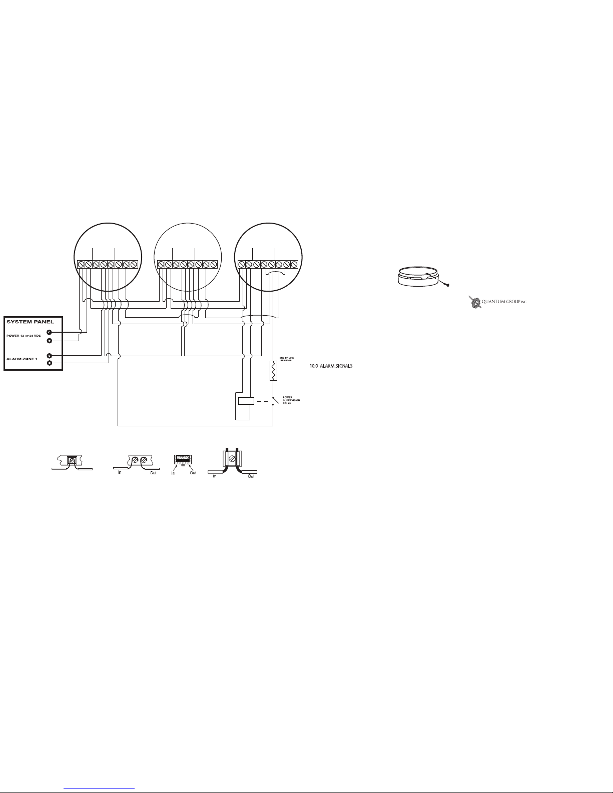
9.5 WIRING INSTALLATION
Internal terminal block for 14-22 AWG wires. 8 screw terminals
at 0.2” (5 mm) spacing.
9.5.1 Drill hole in wall or ceiling at center of plate, and pull sys-
tem wires through the hole.
9.5.2 Remove alarm cover by using the special tool provided on
the three locking tabs on the alarm base. (see figure 4)
Figure 4
9.5.3 Pull wires through hole at center of alarm base and connect
to the internal terminal block as shown on the following wiring dia-
grams. (see figure 5)
Figure 5
NOTE:The form ‘C’ relay contacts may be wired either N.O. or N.C.
according to system panel requirements. These alarms are not
designed to drive auxiliary devices