ASAHI KASEI [AKD4115-A]
<KM076403> 2006/08
- 8 -
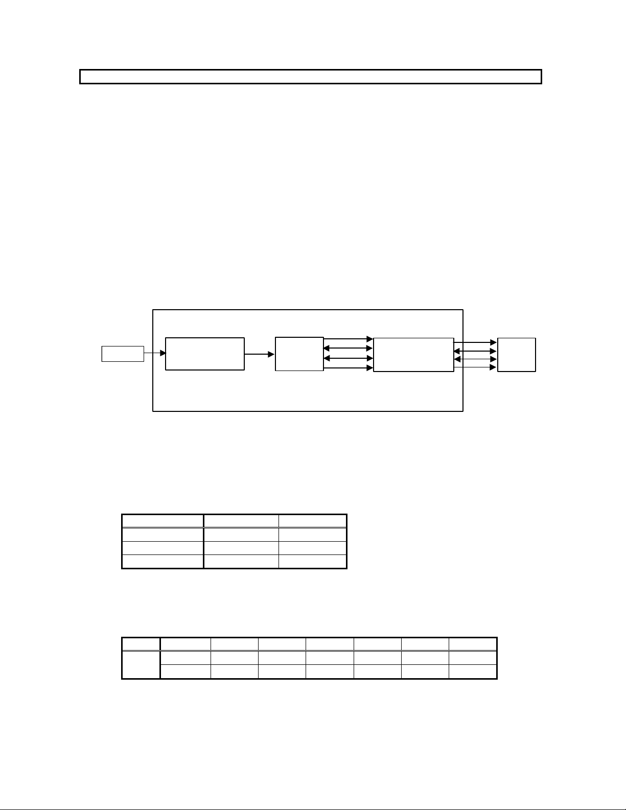
b-2. In the case of the asynchronous mode (ASYNC bit= "1" , This mode is supported in serial mode.)
The used signals are EMCK, X'tal, EBICK, ELRCK, and DAUX. These signal levels outputted / inputted from
PORT5 is 3.3V.
Clock PORT
MCLK PORT5
BICK PORT5
LRCK PORT5
DAUX PORT5
ELRCK PORT5
Table 16. Clock input and output
b-2-1. Set-up of Master clock
When EMCK is used
Output signal MSEL bit JP15
EMCK 1 EMCK
Table 17. Selection of EMCK
When X'tal is used as master clock
Output signal JP12 JP15 JP11
MCKO1 MCKO1 MCKO MCKO1
MCKO2 MCKO2 MCKO MCKO2
Table 18. Selection of MCKO1/MCKO2
b-2-2. Setup of BICK and LRCK input and output
Please set up SW 3_8 (DIT_I/O) according to the setup of audio format of AK4115 (Refer to Table 20).
JP16 and 17 are fixed to the “DC” side.
Audio format SW3_8 (DIT_I/O)
Slave mode 0 Default
Master mode 1
Table 19. DIT_I/O set-up
c. Set-up of audio data format
c-1. In case of synchronous mode.
Please refer to Table 7.
c-2. In case of asynchronous mode
ELRCK EBICK
Mode EDIF1 bit EDIF0 bit DAUX I/O I/O
4 0 0 24bit, Left justified H/L O 64fs O
5 0 1 24bit, I2S L/H O 64fs O
6 1 0 24bit, Left justified H/L I 64-128fs I Default
7 1 1 24bit, I2S L/H I 64-128fs I
Table 20. Audio data format in asynchronous mode