EuroTel ETL0310 Series User manual


EUROTEL – ITALY TV Transmitter ETL0310
Series ETL0310 TELEVISION TRANSMITTER
(INSTALLATION & USE)
TABLE OF CONTENTS
1. INTRODUCTION ................................................................................................................................................ 4
2. SCOPE.................................................................................................................................................................. 4
3. TRANSMITTER CONFIGURATIONS............................................................................................................... 4
4. COMPOSITION ................................................................................................................................................... 4
5. TECHNICAL SPECIFICATIONS ....................................................................................................................... 5
General........................................................................................................................................................................ 5
Video Input Parameters............................................................................................................................................... 5
Audio Input Parameters............................................................................................................................................... 5
I.F. Parameters............................................................................................................................................................ 5
Output Parameters ...................................................................................................................................................... 6
Transmission Quality................................................................................................................................................... 6
Dimensions and Weight ............................................................................................................................................... 6
EC (European Community) Certification and Type Approval..................................................................................... 6
6. FUNCTIONAL DESCRIPTION .......................................................................................................................... 7
General description ..................................................................................................................................................... 7
7. TRANSMITTER CONFIGURATIONS & MODEL NUMBERS ....................................................................... 8
8. INSTALLATION ................................................................................................................................................. 9
Stand Alone Mounting Procedure................................................................................................................................ 9
Controls, Displays & Connectors (front panel) ........................................................................................................... 9
Controls, Displays & Connectors (rear panel).......................................................................................................... 11
Enable IN/OUT DIN socket ....................................................................................................................................... 11
D.C. power input socket (A.C.- D.C. equipment only)............................................................................................... 11
SERIAL DATA COM (RS-232) socket ....................................................................................................................... 12
SERIAL DATA RS-485 socket.................................................................................................................................... 12
E-LINK socket ........................................................................................................................................................... 12
Auxiliary control socket............................................................................................................................................. 13
9. OPERATING PROCEDURES ........................................................................................................................... 14
First Time Operation for Stand Alone Transmitters .................................................................................................. 14
10. METERING POWER SUPPLY MODULE - MULTI-FUNCTION METERING DISPLAY ........................... 14
Alphanumeric LCD display description..................................................................................................................... 15
First level menu description ...................................................................................................................................... 15
Warning LED............................................................................................................................................................. 16
11. ALIGNMENT AND MAINTENANCE INSTRUCTIONS ............................................................................... 16
Procedure L.O.: Operation and set-up of Synthesised Local Oscillator MODM96B................................................ 17
Procedure A.G.C.-A.L.C.: Linearity pre-correction and the R.F. power output – Controller MODM33-6 .............. 18
FIGURES
Figure 1: Television Transmitter ETL0310 .......................................................................................................................... 5
Figure 2: Television Transmitter ETL0310 blocks diagram................................................................................................. 7
Figure 3: Audio input connections. .................................................................................................................................... 10
Figure 4: Enable socket and connector.............................................................................................................................. 11
Figure 5: D.C. input socket ................................................................................................................................................ 11
Figure 6: Serial Data Com in-out socket ........................................................................................................................... 12
Figure 7: Serial DataRS485 in-out socket......................................................................................................................... 12
Figure 8: E-LINK in-out socket.......................................................................................................................................... 12
Figure 9: ETL0310, rear panel of 4 W A class to 10W AB class models, A.C. mains only ................................................ 13
Figure 10: ETL0310, rear panel of 10 W A class to 50 W AB class models, A.C. mains only ........................................... 14
Figure 11: Blocks diagram for pre-correction set-up of TV Transmitters.......................................................................... 19
TABLES
Table 1: List of available products....................................................................................................................................... 4
Table 2: Transmitter modular components .......................................................................................................................... 4
Table 3: Product certification .............................................................................................................................................. 6
Table 4: Model code number................................................................................................................................................ 8
Table 5: Codes for position “9”........................................................................................................................................... 8
Table 6: Examples of model code......................................................................................................................................... 8
Table 7: Front panel control & connection devices referred to Figures 1........................................................................... 9
Table 8: Wiring of audio connector ................................................................................................................................... 10
Table 9: Rear panel connections ........................................................................................................................................ 11
Table 10: Wiring to the Auxiliary Control socket............................................................................................................... 13
Nov 02 CMAN0310ENG 1

TV Transmitter ETL0310 EUROTEL - ITALY
Technical Manual
Series ETL0310 Television Transmitter
AMENDMENT RECORD SHEET
When an amendment to this publication is incorporated, the record below is to be completed and initialled.
Release Language DESCRIPTION AUTHORITY DATE
APPROVAL RECORD SHEET
When an approval to this publication is incorporated, the record below is to be completed.
Release Signature AUTHORITY DATE
© EUROTEL S.r.l.
The information contained herein is the property of EUROTEL S.r.l. and is supplied without liability for errors or omissions and
no part may be reproduced, used or disclosed, except as authorized by contract or other written permission. The copyright
and the foregoing restriction on reproduction, use and disclosure extends to all media in which this information may be
embodied, including magnetic or electronic storage, etc.
WARNINGS
Observe safety precautions when handling this unit. This equipment operates with dangerous voltages and currents.
Always disconnect power before opening covers or removing any part or module of this unit.
2 CMAN0310ENG Nov 02

EUROTEL – ITALY TV Transmitter ETL0310
FIRST AID IN CASE OF ELECTRIC SHOCK
DO NOT TOUCH THE VICTIM WITH YOUR BARE HANDS until the circuit is broken. SWITCH OFF. If this is not possible, PROTECT
YOURSELF with DRY insulating material and pull the victim clear of the conductor. If breathing has stopped, indicated by
unconsciousness, lack of respiratory movements and a ‘blue’ look to cheeks, lips, ears and nails, START RESUSCITATION AT ONCE.
EMERGENCY RESUSCITATION: EXPIRED AIR METHOD
If possible, lay the victim on his back, with his head slightly higher than his feet. Clear the mouth and the throat of any obvious
obstruction.
Kneel on one side of the victim, level with his head. LIFT THE JAW AND TILT THE HEAD
BACK AS FAR AS POSSIBLE. (Figures 1 and 2).
Fig 1
Fig 2
Fig 3
Fig 4
One of the following may now happen:
• Breathing may begin and consciousness return.
• Breathing may begin, but consciousness may NOT return. Turn the victim on his
side and ensure that the airway is kept clear.
• Breathing may return, but be NOISY, which means that the airway is not fully
clear. Try to clear the airway.
If there is no sign of breathing:
Check that the head is still tilted back.
Take a deep breath. Pinch the victim’s nose and blow firmly into his mouth. As you do, his chest
will RISE (Figure 3).
Turn your head away and take another breath, watching for the chest to FALL (Figure 4).
Start with four quick deep breaths and then continue with one breath every five seconds (i.e. 12
times a minute). This should be continued until the victim revives or a doctor certifies death.
As consciousness returns, the victim will start to breathe on his own and a ‘pink’ colour replaces
the ‘blue’ look. This is the time to stop resuscitation. Continue to hold his chin up and so keep
the airway clear.
In the case of injuries to the mouth, it may be necessary to use mouth-to-nose resuscitation.
Seal the victim’s mouth with your cheek and blow firmly into his nose, proceeding as above.
In any case, it is ESSENTIAL to commence resuscitation WITHOUT DELAY and to send for
medical assistance immediately.
TREATMENT FOR BURNS
If the victim is also suffering from burns, then, without hindrance to resuscitation, observe the following:
• Do not attempt to remove clothing adhering to the burns.
• If possible, alleviate the pain from the burn part by immersing in cold water.
• If help is available or as soon as resuscitation is no longer required, the wound should be covered with a DRY clean
dressing.
• Oil and/or grease, in any form, SHOULD NOT be applied. If severely burnt, get the victim to hospital immediately.
Nov 02 CMAN0310ENG 3

TV Transmitter ETL0310 EUROTEL - ITALY
1. INTRODUCTION
The Series ETL0310 Television (TV) Transmitter receives at its inputs Video and Audio programme signals, processes them at standard
I.F. frequency, converts the I.F. signal to the desired transmitting R.F. channel and amplifies the R.F. signal to a power suitable for
Broadcasting or for driving external high power Amplifiers. The TV Broadcasting Transmitter ETL0310 is supplied in two different
versions, depending on the band-pass R.F. output filter. If the Transmitter is to be connected directly to the transmitting antenna, the unit
is supplied with a band-pass filter installed into the chassis (UHF) or outside the chassis (VHF). In this case the model has a TX suffix,
as explained in Section 7. If the Transmitter is used as Exciter for higher power stages, then the band-pass filter is omitted. A complete
selection of options, covering R.F. output, band of operation, TV standards and power supplies, together with ordering information, is
given in Section 7.
2. SCOPE
The scope of this manual is to provide information on the use and operation of the Series ETL0310 TV Transmitter. This manual covers
all Transmitters having outputs in Band III VHF and Bands IV & V UHF. Most of the present information can be used also for
Transmitters having outputs in Band I VHF. The technical information available for the ETL0310 Series Transmitters is given in two
TECHNICAL MANUALS. The first MANUAL, concerns “INSTALLATION & USE”, while the second MANUAL, “TECHNICAL DATA”,
provides in-depth technical information, such as special alignment procedures, schematic diagrams, parts layouts and parts lists. Unless
a special order is made, only the “INSTALLATION & USE” handbook is normally shipped with the equipment.
3. TRANSMITTER CONFIGURATIONS
Depending on the R.F. Amplifiers installed after the Up-Converter, several power outputs and performance configurations are possible,
according to the final application. Class “A” equipment has been designed to drive higher power external R.F. Amplifiers, either solid
state or tube. With class “A” Exciters, most of the pre-correction operational margin can be used to compensate for the distortion of the
R.F. Amplifiers being driven. Class “AB” equipment, delivering higher power in the same size, is better suited for stand-alone operation
with direct connection to the transmitting antenna. In this case the built-in pre-correction is used to compensate the internal R.F.
Amplifiers.
Table 1: List of available products
DESCRIPTION BAND R.F. W CLASS R.F. MODULES MODEL
UHF TV Transmitter IV-V 4 “A” MOE138AA ETL0310TA..
UHF TV Superdriver Transmitter IV-V 10 “A” MOE138NA+MOE140A
ETL0310TC..
UHF TV Transmitter IV-V 50 “AB” MOE138NA+MOE140C ETL0310TH..
VHF TV Transmitter III 10 “A” MOE155A ETL0310TF..
VHF TV Transmitter III 50 “AB” MOE155C ETL0310TG..
VHF TV Transmitter I 10 “A” MOE156A ETL0310TR..
VHF TV Transmitter I 50 “AB” MOE156C ETL0310TQ
4. COMPOSITION
The Series ETL0310 TV Transmitter consists of seven plug-in modules mounted in a standard 3 U 19” rack cabinet. In addition to the
seven plug-in modules, the R.F. Power amplifier(s) are mounted on a heat sink on the rear panel, and a switch mode Power Supply is
mounted on the cabinet wall. The plug-in modules are interfaced by a motherboard through 96-pin type connectors on each card,
equipped, when necessary, with coaxial sockets. The other modules are hard wired into the chassis. All the available modules are
shown below.
Table 2: Transmitter modular components
NORMAL CONFIGURATION MODULES NOTES UHF BIV-V VHF BIII
Video Processor (*) MODM23A MODM23A
Sound Modulator (*) MODM25A MODM25A
Vision Modulator (*) MODM24B MODM24B
A.G.C. - A.L.C. Controller (*) MODM33-6 MODM33-6
Synthesized Local Oscillator (*) MODM 96B MODM96BV3
Up Converter (*) MODM41B MODM41BV3
Metering & Power Supply Unit (+5 V, ±15 V) (*) (**) MODM206 MODM206
Switch Mode Power Supply Unit for R.F. Amplifiers (**) MOE104A10 MOE104A10
OTHER AVAILABLE MODULES NOTES UHF BIV-V VHF BIII
IRDETO system, scrambler adapter (****) MOE77 MOE77
DC fed Power Supply (+5 V, ±15 V, +V for R.F.
Amplifiers)
(***) MOE107 MOE107
Metering (to be used with DC fed Power Supply) (***) MODM27-4 MODM27-4
* Plug in module. ** A.C. fed configuration. *** D.C. fed configuration. **** Plug-in extender type circuit board.
4 CMAN0310ENG Nov 02

EUROTEL – ITALY TV Transmitter ETL0310
Figure 1: Television Transmitter ETL0310
5. TECHNICAL SPECIFICATIONS
General
Primary power........................................................................ 230/240/127/110 V a.c. ±15%, 47 to 60 Hz
Power options ........................................................................+24 V d.c. +20%, -10%
...............................................................................................+48 V d.c., ±20%
Power consumption ...............................................................100W max. full power, 40W max., st-by
(4 W analog and 2W digital RF output power models)
...............................................................................................200W max. full power, 40W max., st-by
(10 W analog and 4W digital RF output power models)
...............................................................................................250W max. full power, 40W max., st-by
(50 W analog and 20W digital RF output power models)
Operating temperature range................................................. 0°C to +45 °C.
Storage temperature range....................................................-10 °C to +70 °C.
Protections & alarms (depending on model)..........................Over voltage (crowbar), over-current,
high HS temperature, excessive reflected power,
low output power..
Video Input Parameters
Number of inputs....................................................................2 with automatic switch
Cross talk attenuation between inputs...................................>56 dB up to 5 MHz
Input signal level ....................................................................1 V p.p.
Input manual gain adjustment................................................± 3 dB
Input impedance ....................................................................75 Ω, unbalanced
Input return loss .....................................................................>30 dB
Video clamping ......................................................................Sync tip or back porch selectable
White clipping set at...............................................................95% of modulation depth
Audio Input Parameters
Number of inputs....................................................................2 with automatic switch
Input signal level ....................................................................+8 dBU at ±50 KHz pk. dev.
Input manual gain adjust........................................................+10/-3 dB
Input impedance ....................................................................600 Ωor >3 kΩ
Test tone nominal frequency..................................................400 Hz
I.F. Parameters
Vision Intermediate Frequency .............................................. 38.9 MHz or as per Standard specified.
I.F. Filter.................................................................................SAW acoustic device.
Different specifications...........................................................EuroTel can provide most TV Standards.
Nov 02 CMAN0310ENG 5

TV Transmitter ETL0310 EUROTEL - ITALY
Output Parameters
Output frequency range .........................................................BANDS IV-V: 470-860 MHz
BAND III: 174-250 MHz
BAND I 47-90 MHz
Output impedance..................................................................50 ohm, unbalanced
Video S/N unified weighted....................................................>62 dB
Audio S/N ratio.......................................................................>60 dB @ 50 KHz deviation
Permissible VSWR.................................................................<1.5
In-band Intermodulation Products..........................................<60 dBc (-8,-10,-16 dB) @ rated output
Spurious suppression ............................................................>60 dB
Harmonic suppression ...........................................................>60 dB
Long term output frequency stability ......................................<0.5 PPM / 6 months
Transmission Quality
Differential Gain error.............................................................<3%
Differential Phase error ..........................................................<3°
Luminance non-linearity.........................................................<5%
ICPM ......................................................................................<3°
Video Amplitude/freq. response.............................................<±0.5 dB within the vision band
Group Delay tolerance ........................................................... <±30 ns
Audio Distortion......................................................................< ± 0.5 % at 1kHz
Audio Amplitude freq. response.............................................< ± 0.5 dB, 40Hz to 15KHz
Dimensions and Weight
Dimensions ............................................................................Std. 19” frame, 482 W x470 D x 135 H, mm.
Weight for 2 W output models................................................12 kg. approx.
Weight for higher power output models .................................15 kg. approx.
EC (European Community) Certification and Type Approval
The ETL0310 TV Transmitter family conforms to Norm prETS 300-339, for TV Broadcasting, according to European Council Directive
89/336/EEC and to the Italian Legislative Decree N°476/1992. This Equipment has obtained the relevant Official Certificate of
conformance N° EMC/97/046 of 07-04-97.
The following table lists the type approvals for the various models of the family and the relevant certificate numbers as of March 1999.
Where the “Certificate” position has not been filled in, the equipment is in the process of being certified. For an up to date situation
please contact EuroTel.
Table 3: Product certification
Model Frequency band R.F. Power W Certificate
ETL0310TF… VHF Band III 10 0003541 of 8/2/99
ETL0310TA… UHF Band IV-V 4 0003543 of 8/2/99
ETL0310TB… UHF Band IV-V 10 0003550 of 8/2/99
ETL0310TC.. UHF Band IV-V 10 0003549 of 8/2/99
6 CMAN0310ENG Nov 02
EUROTEL – ITALY TV Transmitter ETL0310
6. FUNCTIONAL DESCRIPTION
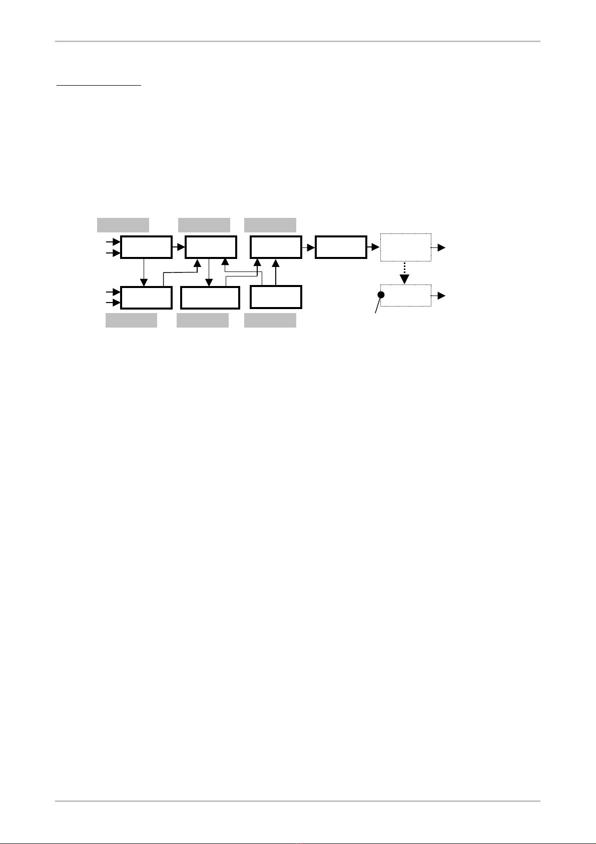
General description
The Series ETL0310 Television (TV) Transmitter accepts at its input the Video programme signal and the Audio programme signal. The
Video signal amplitude modulates the I.F. (Intermediate Frequency) Vision Carrier. The Audio signal frequency modulates the I.F. Sound
Carrier. The Vision and Sound I.F. carrier signals are then combined in the Vision Modulator module. The composite signal is processed
in the A.G.C. - A.L.C. Controller module and then converted to the specified output frequency by the Up Converter module. Output can
be any standard TV Channel in Band IV-V, in Band III or Band I.
Signals Video 1 IN and Video 2 IN enter the Video Processor module where a detector looks for the presence of Video 1. The detector
generates two signals labelled Command -1 and Command -2 which are used in the Audio section to select the Audio 1 or Audio 2
inputs of the Sound Modulator module.
Signals Audio 1 IN and Audio 2 IN are connected to the input of the Sound Modulator module where they are selected by means of the
command signals generated by the Video Processor module, as described above.
R.F. Output
Oscillator
MODM25A
MODM33
-
6
MODM96B
MODM41
MODM24B
MODM23A
Only in stand-alone transmitters
Band-pass
Filter
A.G.C. - A.L.C.
Controller
Vision
Modulator
Local
Up
Converte
r
R.F.
Am
p
lifie
r
Audio 1 IN
Audio 2 IN
R.F. Output
Video 1 IN
Video 2 IN
Additional R.F.
Amplifiers
Sound
Modulator
Video
Processor
Figure 2: Television Transmitter ETL0310 blocks diagram
The Sound Modulator module also receives the 38.9 MHz (or the vision frequency specified by the standard in use) reference signal
coming from the Vision Modulator, and sends the I.F. Sound Carrier output signal to the Vision Modulator module where it is added to
the I.F. Vision Carrier. The tone On/Off switch located on the front panel of the module is used to enable or disable an internal 400 Hz
test tone generator. The Sound Modulator generates D.C. metering signals for Sound level and for Sound carrier deviation, which are
sent to the metering unit, for display on the front panel analogue meter.
The Vision Modulator module receives the Video signal coming from the Video Processor and the Sound Carrier coming from the Sound
Modulator. The Video signal amplitude modulates the I.F. Vision carrier. Finally the composite I.F. signal made with the modulated
Sound and Vision carriers is sent to the A.G.C. - A.L.C. Controller module. The Carrier frequency IN/OUT socket can be used as monitor
of the internal oscillator or as external oscillator input.
The I.F. frequency PLL high stability circuit receives the 5 MHz reference frequency from the Local Oscillator Synthesiser module and
locks the I.F. Vision carrier generator of the Vision Modulator module to the reference of the Synthesised Local Oscillator. Therefore all
carrier frequencies within the Transmitter are locked to a single reference.
The I.F. signal output from the Vision Modulator module enters the A.G.C. - A.L.C. Controller module that incorporates several signal
processing circuits and devices, as follows :
• The A.G.C. section keeps the I.F. level in the A.G.C. - A.L.C. Controller module constant.
• The A.L.C. section keeps the output R.F. signal at constant level by varying the amount of I.F. signal fed to the Up Converter
module.
• Switches A.G.C. / m.g.c and A.L.C. / m.l.c. are used for testing and alignment.
• Switch PREC. ON/OFF controls the insertion of the linearity pre-corrector for the output stages. Pre-correction is made at I.F.
frequency.
• Screwdriver controls directly accessible from the front panel of the A.G.C. – A.L.C. Controller allow easy adjustment of the R.F.
output power, either in manual mode (open loop) or in A.L.C. mode (closed loop).
After this processing, the I.F. signal leaves the A.G.C. - A .L.C. Controller module and enters the Up Converter module, which also
receives the appropriate conversion signal from the Local Oscillator module at a frequency above the transmitted vision carrier
frequency. The difference between conversion signal and transmitted vision frequency is the value of the I.F. frequency specified by the
standard in use.
The R.F. OUT signal output from the Up Converter Module is sent to the R.F. Amplifier stages. The basic Transmitter has a power
output of 4 W. Different R.F. Amplifier modules are installed to achieve the required power output. Amplifiers are based on LDMOS
technology.
An output band-pass filter is supplied if the Transmitter is specified for stand-alone operation, (without an external R.F. output amplifier).
The A.C. ONLY mains fed Transmitter has a Power Supply arrangement that works as follows: the On/Off switch on the front panel turns
the equipment on by controlling the A.C. input to the mains transformer and a green LED is lit when the mains voltage is enabled. This
transformer feeds rectifiers that provide raw D.C. power to two different power supplies. The first supply is the Metering - Power Supply
module that provides the + 5 V and ± 15 V D.C. The second supply module is a Switch Mode Power Supply that generates the D.C.
voltage needed by the R.F. power amplifiers.
Nov 02 CMAN0310ENG 7

TV Transmitter ETL0310 EUROTEL - ITALY
The A.C. - D.C. fed Power Supply option allows operation from 220/230 V mains as well as + 24 V D.C. or + 48 V D.C. (depending on
option). In this case the input D.C. voltage is used by a switch mode power supply to generate the + 5 V, ± 15 V and the D.C. voltage
used by the R.F. Amplifiers. The ON/OFF switch on the front panel controls the A.C. & D.C. input power. A yellow LED indicator turns on
when the ON/OFF switch is enabled.
The metering unit is used to monitor signals and supply voltages and provides the following additional features.
• Protection against excessive R.F. drive to the final R.F. Power Amplifier.
• Protection to the final R.F. Power Amplifier for excessive reflected power.
• Alarm for low output power.
Additionally, alarms corresponding to the above conditions are also provided, by means of hard-wired relay contacts, to the Auxiliary
Control Connector located on the rear apron of the Transposer.
7. TRANSMITTER CONFIGURATIONS & MODEL NUMBERS
The model number of the ETL0310 Transmitter is a 15-position code as follows:
Table 4: Model code number
1 2 3 4 5 6 7 8 9 10 11 12 13 14 15
E T L 0 3 1 0 T
power
&
band
freq.
genera
tion
I.F.
PLL
- TV Std. spare
or
T
spare
or
X
Positions 1to 8are fixed and never change.
Position 9specifies power output, band of operation and operating class of final R.F. Amplifier with the following letter code. Blank
spaces are reserved to equipment on special order or under development.
Table 5: Codes for position “9”
Po W Band Class Position 9
4 UHF IV-V “A” A
10 UHF IV-V “A” C
50 UHF IV-V “AB” H
10 VHF III “A” F
50 VHF III “AB” G
10 VHF I “A” R
50 VHF I “AB” Q
Position 10 defines type of frequency generation. EuroTel now only supplies Synthesised Local Oscillators as standard equipment, so
that there is always Sin this position.
Position 11 defines whether or not the I.F. PLL circuitry is included or not. Being included as standard equipment, there is always Pin
this position.
Position 12 is a separation mark: - .
Position 13 defines the TV Standard and is not used for standards B and G. For other standards such as M, K, Ietc., then the
corresponding letter is used.
Positions 14 and 15 are spare and/or used when the output band-pass filter is built-in, for direct connection to the antenna. In this case
the letters Tand X are used.
IMPORTANT: when a position is not used, its place is taken by the next position, in order to always form a code with no gaps.
NOTE: Equipment with R.F. output up to 10 W can optionally work off D.C. supplies (+ 24 or + 48 V D.C.). Relevant options, to be
added after the 15-position code are:
• 220V A.C. & + 24 V D.C.: OPT. 0016.
• 220V A.C. & + 48 V D.C.: OPT. 0015.
Table 6: Examples of model code
Description Code
UHF Band IV-V, 10 W Synthesised TV Transmitter, Std. M, for driving Solid State R.F. Amplifier ETL0310TCSP-M
UHF Band IV-V, 50 W Synthesised TV Transmitter, Standard G, B pass filter installed ETL0310THSP-TX
UHF Band IV-V, 50 W Synthesised TV Transmitter, Standard M, B pass filter installed ETL0310THSP-MTX
UHF Band IV-V, 4 W Synthesised TV Transmitter, Std. G, B pass filter installed ETL0310TASP-TX
VHF Band III, 10 W Synthesised TV Transmitter, Standard I, B pass filter installed ETL0310TFSP-ITX
8 CMAN0310ENG Nov 02

EUROTEL – ITALY TV Transmitter ETL0310
8. INSTALLATION
The Series ETL0310 Television (TV) Transmitter is constructed in a 3U drawer that can be mounted in a 19” standard rack cabinet. The
Transmitter can be supplied for stand-alone service, or for direct connection to the antenna: (TX suffix). In this case a band-pass filter is
internally (UHF output) or externally (VHF output) installed. When the Transmitter is supplied for driving an external R.F. Amplifier, the
band-pass filter is omitted.
NOTE: When the Transmitter is intended for use with scrambled TV signals using sync suppression techniques, such as IRDETO or M-
NET type signals, the sync pulse is missing and the Transmitter has been programmed to disable (by means of internal Jumpers) all
pulse driven circuitry. In such Transmitters the “Economy” circuitry is disabled.
Stand Alone Mounting Procedure
Check that all the plug-in modules are correctly inserted and fastened to the drawer. Insert the drawer in its selected place in the cabinet
(if available) and fasten with four rack screws (not supplied). Leave at least 1U of free space above and below the Transmitter to obtain
adequate cooling. Make sure the front panel mounted ON/OFF switch is in the “OFF” position.
Connect the R.F. “N” type plug from the Transmitting Antenna cable to the R.F. OUTPUT socket of the Transmitter, this socket is
located on the rear panel.
Connect the main video programme signal to the VIDEO 1 IN socket of the Transmitter. Connect (if available) the secondary video
programme signal to the VIDEO 2 IN socket of the Transmitter. These sockets are located on the front panel of the Video Processor
plug-in module.
Connect the main Audio programme signal to the AUDIO 1 IN socket of the Transmitter. Connect (if available) the secondary Audio
programme signal to the AUDIO 2 IN socket of the Transmitter. These sockets are located on the front panel of the Sound Modulator
plug-in module.
Connect the 220 V A.C. plug into the A.C. receptacle located on the rear panel of the Transmitter.
The green led “Driver enabled” on the A.G.C.- A.L.C. Controller front panel lights when the Transmitter is enabled to transmit (internally
or externally), and the Local Oscillator is locked.
NOTE: The jumper J1 in the A.G.C-A.L.C. Controller module sets the enabling function as follows:
• Jumper J1 positioned in Ext. position: Transmitter is enabled to transmit with external voltage.
• Jumper J1 positioned in Int. position: Transmitter is enabled to transmit as soon as the mains switch is actuated.
NOTE: The Auxiliary control socket carries several relay contacts for various alarm conditions. Please refer to Table 10 for wiring
information.
First time operation and other relevant instructions are given in Section 9, OPERATING PROCEDURES, following.
Controls, Displays & Connectors (front panel)
Table 7: Front panel control & connection devices referred to Figures 1
PLUG-IN ITEM DESCRIPTION
VIDEO PROCESSOR VIDEO 1 IN BNC socket, main (preferred) video input
Gain trimmer Screwdriver adjustment of video 1 gain.
VIDEO 2 IN BNC socket, secondary video input.
Gain trimmer Screwdriver adjustment of video 2 gain.
Video 1 present (green) Lit when video 1 and audio 1 are selected
Switch position (yellow) Lit when video 2 and audio 2 are selected
White clipping (red) Lit in white clipping
SOUND MODULATOR AUDIO 1 IN DIN socket, main (preferred) audio input.
Gain trimmer Screwdriver adjustment of audio 1 gain.
Audio 2 IN DIN socket, secondary audio input.
Gain trimmer Screwdriver adjustment of audio 2 gain.
Sound C.er OUT SMB socket. Outputs the frequency modulated I.F. sound
carrier to Vision Modulator SOUND 1 IN.
Carrier on LED (green) Lit when the sound carrier is locked to the vision carrier and the
sound carrier is enabled.
Tone ON/OFF Switches audio test tone on and off.
VISION MODULATOR SOUND 1 IN SMB socket. Inputs the modulated sound carrier.
Level Screwdriver adjustment of the vision-sound level ratio.
SOUND 2 IN SMB socket. Inputs external dual sound or Nicam carrier.
Level Screwdriver adjustment of the Sound 2 input sensitivity.
I.F. OUT BNC socket. Outputs the composite I.F. signal.
I.F. OUT BNC socket. Outputs the composite I.F. signal for monitoring.
C.er freq. in/out BNC socket. Depending on internal Jumpers: a) vision carrier
frequency monitor or b) external vision carrier input.
Nov 02 CMAN0310ENG 9

TV Transmitter ETL0310 EUROTEL - ITALY
A.G.C.–A.L.C. CONTROLLER A.G.C. on/off Switches Automatic Gain Control on or off.
m.g.c. trimmer Screwdriver adjustment of I.F. gain in manual mode.
m.l.c. trimmer Screwdriver adjustment of I.F. output level in manual mode.
A.L.C. ON/OFF Switches Automatic Level Control on or off.
a.p.l. LED (yellow) Lit when the Average Power Limiter is in operation.
Carrier loss LED (red) Lit for insufficient level of I.F. input signal to the module.
Economy LED (red) Lit in stand-by, waiting for a video modulated I.F. carrier.
Driver enabled LED (green) Lit when the L.O. is locked and Transmitter is enabled.
I.F. MONITOR BNC socket. Monitors processed I.F. output.
I.F. OUT BNC socket. Outputs processed I.F. to Up Converter.
I.F. IN BNC socket. Inputs composite I.F. signal to be processed.
PREC. on/off Switches pre-correction circuits in or out.
Trimmers K1, K2 & K3 Screwdriver adjustments of pre-correction circuits.
Power trimmer Screwdriver adjustment for setting R.F. output in A.L.C. mode.
UP CONVERTER L.O. IN BNC socket. Inputs R.F. signal from Synthesised L.O.
I.F. IN BNC socket. Inputs I.F. signal from A.G.C. – A.L.C. Controller.
SYNTHESISED L.O. L.O. OUT BNC socket. Outputs R.F. L.O. signal to Up Converter.
L.O. MONITOR BNC socket. Outputs R.F. L.O. signal for monitoring purposes.
UP, DWN. & SEL. Push buttons to operate display & synthesiser.
Display Provides complete L.O. parameter info. Refer to Section 10.
MULTIMETER-PSU Display Displays many working parameters.
ALARM LED (red) When lit, this LED indicates that one alarm has occurred.
WARNING LED (yellow) Indicates one or more warning conditions in act, if blinking
indicates alarm or warning stored in the EEPROM non-volatile
memory.
LINE LED (green) Lit when A.C. power has been switched on.
SELECT Controls the menu levels and is menu driven, as explained in
detail in the “MENU DESCRIPTION” following.
~
Normally controls the lower row of the display and is menu
driven.
~ Normally controls the upper row of the display and is menu
driven.
PREV. Controls the menu levels and is menu driven, as explained in
detail in the “MENU DESCRIPTION” following.
(A.C. – D.C. Equipment only) D.C. LINE LED Lit when D.C. power has been switched on.
Power ON/OFF Main switch on.
Audio input connections
1
2
3
Table 8: Wiring of audio connector
CONNECTION PIN 1 PIN 2 PIN 3
Balanced Audio Input Ground Audio Input
Unbalanced Audio Input Ground Ground
Figure 3: Audio input connections.
10 CMAN0310ENG Nov 02

EUROTEL – ITALY TV Transmitter ETL0310
Controls, Displays & Connectors (rear panel)
According to power supply used and to R.F. output power, different versions of the back panel are used. The controls and connectors
on the rear panel are as follows:
Table 9: Rear panel connections
REAR PANEL ITEM DESCRIPTION
SIGNALS AND EXTERNAL
CONNECTIONS
ENABLE IN/OUT Din type socket used to send the enable voltage to an
external R.F. power amplifier and to receive the “ready
signal” from an external R.F. power amplifier.
AUX. CONTROL D type 25-pin socket. Provides status signals and accepts
external control signals.
REF.in (5/10MHz) BNC socket for external reference frequency input.
REF.out (5/10MHz) BNC socket for output of internal 5 MHz reference
frequency for Precision Offset operation. Not mounted on
standard equipment.
ALC in (P 203) BNC socket for A.L.C. input from external R.F. Amplifiers.
R.F. monitor BNC socket for R.F. monitor
RS485 Type “D”, 9-pin socket. Makes RF Amplifier parameter
data available for display on an external PC or monitoring
system. (RS-485 format)
E-LINK Type “D”, 9-pin socket, to be connected to the external
amplifier.
R.F. OUT Type “N” socket. R.F. output to the transmitting antenna or
to an external R.F. Amplifier.
A.C. POWER INPUT
INTERCONNECTION
LINE IN A.C. mains socket.
FUSES A.C. mains fuses.
D.C. POWER INPUT
INTERCONNECTION
D.C. POWER IN D.C. power input socket.
FUSE D.C. input fuse.
FUSE D.C. input fuse.
Enable IN/OUT DIN socket
Pin 1: + 15 V. Enable output to external R.F. Amplifier.
Pin 2: Ground.
Pin 3: + 10 V (nominal). Transmitter ENABLE input.
Socket seen from
back panel of
equipment
3
2
1
Figure 4: Enable socket and connector
This socket is used: (a) to enable the Transmitter with an external command of +10 V nominal and (b) to co-ordinate the operation of the
Transmitter with an external R.F. Amplifier, by means of an inter-connection cable supplied with the equipment.
When the Transmitter is programmed for stand-alone operation, it is self-enabled by an internal Jumper (J1) connection on module
MODM33-6. With this connection the Transmitter will turn on as soon as the front panel ON-OFF switch is set to “ON”.
D.C. power input socket (A.C.- D.C. equipment only)
Pin 1: Positive supply voltage.
Pin 2: Negative supply voltage
Pin 3: Not used.
Pin 4: Ground.
Socket seen from
back panel of
equipment
3
2
1
Figure 5: D.C. input socket
This socket is installed only in A.C. – D.C. (24 or 48 V) equipment and is used to input the D.C. supply.
NOTE: If supply voltage polarity is reversed in 24 V equipment, D.C. fuses located on the rear panel will immediately fail, protecting the
equipment. Accidental polarity inversion in 48 V equipment has no consequence, because a series protection diode is installed: the
Transmitter will not work until the polarity is reversed.
Nov 02 CMAN0310ENG 11

TV Transmitter ETL0310 EUROTEL - ITALY
SERIAL DATA COM (RS-232) socket
Figure 6: Serial Data Com in-out socket
PIN DESCRIPTION
1 Not connected.
2 TX out
3 RX in
4 RX c.er
5 Ground.
6 Not connected.
7 Not connected.
8 TX c.er
9 Not connected.
SERIAL DATA RS-485 socket
Figure 7: Serial DataRS485 in-out socket
PIN DESCRIPTION
1 TX Data +
2 TX Data -
3 RX Data -
4 RX Data +
5 Ground.
6 Not connected.
7 Not connected.
8 Not connected.
9 Not connected.
E-LINK socket
Figure 8: E-LINK in-out socket
PIN DESCRIPTION
1 Not connected.
2 CAN low
3 GND
4 Not connected.
5 Shield
6 Not connected.
7 CAN high
8 Not connected.
9 Not connected.
12 CMAN0310ENG Nov 02

EUROTEL – ITALY TV Transmitter ETL0310
Auxiliary control socket
This is a 25-pin DIN type socket, which may be used to make external connections, as shown in Table 10 below.
Table 10: Wiring to the Auxiliary Control socket
PIN DESCRIPTION
1 + 15V enable output. Enables external R.F. Amplifier.
2 Ground.
3 Common contact of “Economy” relay.
4 Contact of “Economy” relay: closes in “Economy”, e.g. no vision programme input.
5 Contact of “Economy” relay: opens in “Economy”, e.g. no vision programme input.
6 Video input loss signal, closed to GND in alarm condition
7 Contact of Sound Carrier alarm: open in normal, closed to ground in alarm.
8 Not used in Transmitter, only used for ETL0290 Transposers.
9 Signal: Up Converter L.O. locked to internal reference and operating normally.
10 Ground.
11 Not connected
12 Not connected.
13 Not connected.
14 External enable input. +10 V (nominal) input to enable Transmitter by remote command.
15 Ground.
16 Spare
17 Carrier loss signal: indicates loss of I.F. signal at A.G.C. - A.L.C. Controller input.
18 Contact of Vision Carrier alarm: open in normal, closed to ground in alarm.
19 Configurable alarm, common contact.
20 Configurable alarm contact, closed in alarm condition. (Default = low power alarm)
21 Configurable alarm, closed in alarm condition.
22 Configurable alarm. Common contact.
23 Ground.
24 Up Converter Loop (special applications).
25 Ground.
RF monitor
E-LINK
RS485
Spare
R.F. Output
A
LC IN (P203)REF.IN
REF.out
ENABLE
IN/OUT
LINE IN
(MAINS)
FUSES
(push out)
AUX. CONTROL
Figure 9: ETL0310, rear panel of 4 W A class to 10W AB class models, A.C. mains only
Nov 02 CMAN0310ENG 13

TV Transmitter ETL0310 EUROTEL - ITALY
E-LINK
REF.out RF monitor
R.F. OUTPUT
RS485
A
LC IN (P203)
REF.IN
ENABLE
IN/OUT
LINE IN
(MAINS)
FUSES (push out)
AUX. CONTROL
Figure 10: ETL0310, rear panel of 10 W A class to 50 W AB class models, A.C. mains only
9. OPERATING PROCEDURES
CAUTION
In any case, but especially when driving external R.F. Power Amplifiers which are within the A.L.C. control loop, do not
attempt to remove and then re-insert the front panel coaxial interconnecting cables while the equipment is in operation.
Although suitable protection circuitry is in place, sudden loss and re-application of R.F. drive causes transients that may
damage one or more R.F. amplification stages.
In any case, but especially when driving external R.F. Power Amplifiers which are within the A.L.C. control loop, do not
change position of the switch A.G.C. – m.g.c. while the equipment is in operation. Although suitable protection circuitry is
in place, very high and sudden variations of R.F. drive cause transients that may damage one or more R.F. amplification
stages.
First Time Operation for Stand Alone Transmitters
Place the A.G.C. switch in the “ON” position. Place the A.L.C. switch in the “ON” position. Place the PREC. (pre-correction) switch in the
“ON” position. Place the Tone switch in the “OFF” position. Place the enphasis switch in the “ON” position The Transmitter is now ready
to be switched on.
Turn the ON-OFF switch to “ON”. On turn on the front panel display of the L.O. Synthesiser shows the SELF-TEST sequence. The
Synthesiser then shows the programmed-in channel number and the equipment starts normal operation.
Check that the “Video 1 present” on the VIDEO PROCESSOR module is on, indicating detection of Video signal at VIDEO IN 1.
Check that the “Pix carrier alarm” on the VISION MODULATOR module is extinguished, indicating vision carrier oscillator working and
loked.
Check that the “carrier on” green LED on the SOUND MODULATOR module is lit, indicating that the Sound Carrier is locked to the
Vision Carrier frequency, hence Transmitter is internally enabled.
Check that the CARRIER LOSS red LED is extinguished, indicating presence of I.F. signal at the I.F. input connector of the A.G.C. -
A.L.C. Controller module.
Check that the DRIVER ENABLED green LED is lit, indicating that the Up Converter Local Oscillator is locked and that the D.C. supply
to the output R.F. Amplifier is enabled. Verify that the red ECONOMY LED and that the yellow a.p.l. LED are extinguished.
Check the channel display on the L.O. for the Up Converter module (sixth from left) to conform to the desired output channel. If different,
follow the channel changing procedures outlined in Procedure L.O., following. Also check for channel Offset, if used, following the
already mentioned procedures.
Using the Metering Power Supply module, check Video level, Sync. level, Audio level, Deviation level, R.F. output power and supply
voltages. R.F. output power can be adjusted by turning the POWER screwdriver control on the A.G.C. - A.L.C. Controller panel.
10. METERING POWER SUPPLY MODULE - MULTI-FUNCTION METERING DISPLAY
14 CMAN0310ENG Nov 02

EUROTEL – ITALY TV Transmitter ETL0310
Alphanumeric LCD display description
Below we list the parameters displayed in an order that is logical and may not correspond to the actual sequence. The two rows of the
alphanumeric LCD display can be indifferently configured to show one of the following quantities.
Push the lower button ~ Sets the quantity to be shown in the upper row, or row #1.
Push the upper button ~Sets the quantity to be shown in the lower row, or row #2.
Vsupply 1 = 5 V Shows the regulated output voltage of the power supply.
Vsupply 2 = 15 V Shows the regulated output voltage of the power supply.
Vsupply 3 = -15 V Shows the regulated output voltage of the power supply.
Vsupply 4 = 28 V Shows the regulated output voltage of the power supply.
VideoLev = ....V Shows the Video level
Sinc Lev = ....V Shows the Video Sinc. level
Aud1 = .... Shows the Audio 1 level
AudDev1 = ....Kz Shows the sound carrier 1 peak deviation.
Aud2 = .... Shows the Audio 2 level
AudDev2 = ....Kz Shows the sound carrier 2 peak deviation.
HS temp = ....°C Shows the temperature of the heat sink.
FWD peak = ....W Shows the forward peak output power of the Vision carrier.
FWD avrg = ....W Shows the forward average output power of the Vision carrier.
RFL peak = ....W shows the reflected peak output power of the Vision carrier
RFL avrg = ....W Shows the reflected average output power of the Vision carrier.
RX Field = ....dBm Shows the RX field in dBm.
First level menu description
To set any particular menu, repeatedly push the SELECT button, until the required menu title appears. Then the required action is
selected pushing →. Finally the selected action is stored by pushing SELECT a second time. Pushing SELECT a third time brings up the
next menu and so on. For more detail see examples in the next pages.
⇒
⇒
⇒
⇒
⇒
⇒
⇒
⇒
⇒
⇒
⇒
⇒
⇒
First level menu
Display contrast (Changes the alphanumeric LCD display contrast)
Display contrast +
Display contrast -
Vision Frequency (Shows approximately the frequency of the Vision carrier at
witch the amplifier is working)
View warning log (Shows the last warning conditions)
View warning log +
View warning log –
Clear (Clears the non-volatile RAM memory)
View alarms log (Shows the last alarm conditions)
View alarms log +
View alarms log –
Clear (Clears the non-volatile RAM memory)
Nov 02 CMAN0310ENG 15
TV Transmitter ETL0310 EUROTEL - ITALY
⇒
⇒
⇒
⇒
⇒
Store LCD view
Clic sel to store
Turn PWR ON/OFF (Configure the R.F. output power enable)
Output PWR= ON (R.F. output Amplifier enabled)
Output PWR= OFF (R.F. output Amplifier disabled)
Warning LED
The yellow WARNING LED is normally dark. It turns on to indicate that one or more operating parameters have risen above the normal
limiting values. This LED blinks if some past warnings and alarms are stored in the EEPROM non volatile memory of the
microprocessor.
To clear this LED the alarm and warning memories have to be cleared. This can be done only during normal operation and when no
warning or alarm conditions exist. To clear the memories, proceed as follows.
• Repeatedly push the SELECT button, until “View warning log.” appears.
• Push button →to enter this menu.
• Push CLR. The display will show: “** Cleared **”.
• Then repeatedly push the SELECT button, until “View alarms log.” appears.
• Push button →to enter this menu.
• Push CLR. The display will show “** Cleared **”. At this point the yellow WARNING LED will go off.
11. ALIGNMENT AND MAINTENANCE INSTRUCTIONS
In this section we give detailed maintenance and alignment procedures. When an external R.F. Amplifier is used, also refer to the
technical manual of the Amplifier for details.
Table 11: Alignment & Maintenance information
DESCRIPTION MANUAL SECTION MODULE
Change Transmit channel, Up-Converter This manual Up Converter MODM41B
Change Transmit channel, Local Oscillator This manual Procedure L.O. MODM96B
Change Transmit channel, Output Filter (UHF) This manual Output Filter ETL2133XX
Change Transmit channel, Output Filter (VHF) This manual Output Filter ETL2130XX
Change Transmit channel, external R.F. Amplifier R.F. Amplifier Amplifier manual
Linearity pre-correction This manual Procedure A.G.C.-A.L.C. MODM33-4
Setting up the Protection-Alarms module This manual Protection & Alarms MODM134
Setting up the Frequency Offset This manual Procedure L.O. MODM96B
To change the Transmit channel, when the Transmitter is in stand-alone configuration, four different procedures must be followed:
• Re-tune channel filter located in Up-Converter plug-in MODM41.
• Change operating channel of the Local Oscillator plug-in MODM96B.
• Re-tune output R.F. band-pass filter.
• Re-set R.F. output power and pre-correction.
To change the Transmit channel, when the Transmitter drives an external R.F. Amplifier, five different procedures must be followed:
• Re-tune channel filter located in Up-Converter plug-in MODM41.
• Change operating channel of the Local Oscillator plug-in MODM96B.
• Change the operating band of the external R.F. Amplifier, if applicable (software command).
• Re-tune output R.F. band-pass filter in the external R.F. Amplifier.
• Re-set R.F. output power and pre-correction.
To change the offset:
• PROCEDURE L.O.: Change offset of Local Oscillator plug-in MODM96B.
16 CMAN0310ENG Nov 02

EUROTEL – ITALY TV Transmitter ETL0310
Procedure L.O.: Operation and set-up of Synthesised Local Oscillator MODM96B
Normal operation: start-up sequence
Note: The front panel is equipped with an alphanumeric display and three pushbuttons: UP, DWN. and SEL.
O At turn on the front panel display shows the following sequence: EUROTEL – BUILD DATE.
The display then shows: L.O. CHANNEL = CH “NN”, where “NN” represents the working channel number. Then the display
automatically locks to: CH “NN” and normal operation begins.
Normal operation: gathering information from the alphanumeric display
Pushing UP once the ACTUAL OFFSET IN Hz, comes on the display. After a few seconds, the display reverts back to the operating
channel number. This is the nominal operating frequency offset set by the Microprocessor circuitry.
Next push of UP button: VCO LOOP VOLTAGE. This voltage is typically from 6.0 to 8.0 V, but any value between 2.0 and 12.0 V does
not impair Synthesizer performance.
Next push of UP button: REF D.C..: Shows the dc voltage to the internal reference crystal oscillator.
Pushing UP once the L.O. FREQUENCY, comes on the display. After a few seconds, the display reverts back to the operating channel
number. This is the nominal operating frequency set by the Microprocessor circuitry.
Next push of UP button: COUNT ERR. Shows the number error of the internal frequency counter, must be less than +- 2
All the following readings are obtained by pushing the UP button quickly, before the display reverts to the channel number.
Channel set-up instructions
This procedure begins with the Equipment switched off and the Local Oscillator installed on the extension board. Push SELECT, then
switch the Equipment on and verify the previously described turn-on sequence. Release the SELECT pushbutton.
Push SELECT again to enter the set-up menu. Display shows: SELECT FUNCTION. We are now inside the modification menu and with
every new actuation of the SELECT button, we enter into a new modification function.
Push SELECT again: you now have entered the OFFSET menu. Display shows: SET LO OFFSET.
Push SELECT again: you now have entered the INTERNAL REFERENCE menu. Display shows: INT REF ADJ.
Push SELECT again: you now have entered the CHANNEL menu. Display shows: SET LO CHANNEL.
Push UP to activate the CHANNEL menu. Display shows the NN number, corresponding to the previously entered channel.
Now push UP or DWN to select the desired CHANNEL NUMBER.
Once you have reached the desired channel, push SELECT to store the channel in the memory. The display shows STORED and then
“- - -“.
After approximately 10 seconds, the display shows the LOOP VOLTAGE of the Phase Locked Loop. The display shows: VCO LOOP =
R.R.
The VCO must now be tuned to bring the system into lock. Locate the cylindrical trimmer capacitor C88 on the PCB, under the VCO
shield box, and carefully adjust for a LOOP VOLTAGE of approximately 7 V. Turn C88 clockwise to increase and counter-clockwise to
decrease the tuning voltage.
Now switch the equipment off and on again to exit the set up menus and to revert to normal operation. Turning the equipment back on
will show the normal start up sequence, which will end by displaying the newly set channel number.
Internal Reference Frequency adjustment
NOTE: This adjustment is done without applying the reference frequency.
The pushbutton that allows to access the modification functions is the SELECT pushbutton.
Push the SELECT pushbutton few times till the INT REFERENCE ADJ menu will appear
Push the UP pushbutton to activate the function: a voltage from 0 to 12V showing the tuning voltage of the internal reference crystal
oscillator, will appear.
Push the UP or DWN pushbutton to adjust the internal frequency, checking the output frequency of the local oscillator through a
frequency counter.
Once the frequency has been set to the desired value, push the SELECT pushbutton to store it. The alphanumeric display will show
STORED, and after few seconds the display will automatically return to show the operating channel.
If the oscillator is externally locked (or internally locked as in the down converter LO case) the display will show DC LOCK VALUE
followed by the V.C.X.O. loop tuning voltage, pushing select again this voltage will be stored as reference voltage.
Nov 02 CMAN0310ENG 17

TV Transmitter ETL0310 EUROTEL - ITALY
Offset set-up instructions
IMPORTANT NOTE: The desired value of frequency offset is selected in Hz, the circuit will choose the closest possible frequency.
This procedure doesn’t require to pull out the Local Oscillator module and/or the use of the extension card since this function can be
accessed from the front panel. Furthermore the OFFSET function doesn’t require the turn-off and subsequent turn-on of the equipment
to assess the function, but it can always be used with the equipment in operative condition.
Push the SELECT pushbutton to enter the set-up menu. The SELECT FUNCTION reading will appear.
Push once again the SELECT pushbutton: we are now in the OFFSET function. The reading SET LO OFFSET will appear.
Push the UP pushbutton to activate the menu. The display will show “0”.
Now it is necessary to set the required value of Offset digit by digit in Hz, starting from first most significant digit up to the last, finally it
has to be defined if the value will be positive or negative.
Push the UP or DOWN pushbutton to select the most significant digit and subsequently push the SELECT pushbutton to confirm.
Continue with the same criteria by pushing the UP or DOWN pushbutton to select ,and the SELECT pushbutton to confirm all other
digit up to the last.
Finally push the UP or DOWN pushbutton to choose the sign of the set value by selecting “+” if the value is positive or “–“ if the value
is negative and then push SELECT to confirm.
The alphanumeric display will show the reading STORED, after few more seconds the display will automatically return to show the
operative channel.
Example CH45 UHF Std G:
Requested Offset value: +10450 Hz
• Enter the menu SET LO OFFSET and push the UP pushbutton
• Select the digit 1 through the UP or DOWN pushbutton, and then push SELECT
• Select the digit 0 through the UP or DOWN pushbutton, and then push SELECT
• Select the digit 4 through the UP or DOWN pushbutton, and then push SELECT
• Select the digit 5 through the UP or DOWN pushbutton, and then push SELECT
• Select the digit 0 through the UP or DOWN pushbutton, and then push SELECT
• Select + through the UP or DOWN pushbutton, and then push SELECT
• The display shows STORED.
Maintenance instructions
Jumper controls the operation of the internal reference VC.X.O. and is factory set.
Socket P8: programming serial port
Jumper P7, P10: position 2-3: normal operation;
position 1-2: microprocessor programming mode.
Jumper P3: with this solder jumper closed connection, the V.C.X.O. control terminal is brought outside the plug-in. This jumper is
normally used when the plug-in has to work in connection with Reference Processor module MODM102T in transposer operation
Precision Offset mode.
Procedure A.G.C.-A.L.C.: Linearity pre-correction and the R.F. power output – Controller MODM33-6
General guidelines
In a Television Transmitter, the linearity/phase pre-correction compensates the linearity/phase distortion of R.F. power amplifiers by
introducing a symmetrical and contrary distortion at I.F. level. The following points must be considered, when looking at pre-correction of
R.F. Amplifiers, because the distortion of amplifiers working in class “A” is different from the distortion generated by amplifiers in class
“AB”.
Amplitude distortion in class “A” amplifiers has in general the nature of signal compression and prevails at the maximum amplitude of
the R.F. modulated signal (i.e. at the level of the sync pulses and of the black). Phase distortion is in general low or very low.
Amplitude and phase distortion in class “AB” amplifiers appear at all levels of amplitude of the R.F. modulated signal. Therefore a
certain set of pre-correction parameters is valid for a certain R.F. power output. If output level is increased or decreased, pre-correction
must be re-adjusted. Hence the importance for an accurate and stable A.L.C., which will keep R.F. output constant regardless of system
gain variations.
18 CMAN0310ENG Nov 02
EUROTEL – ITALY TV Transmitter ETL0310
The theoretical consequence from the above is that the positioning of the pre-correction trimmers will be different, depending on the
operating class of the R.F. amplifier to be corrected. In practice the difference is not as great as it could be expected, because normally
R.F. Amplifiers consist at least of a driver stage (that can be in class “A” or in class “AB”) followed by a final stage, that generally works
in class “AB”. Therefore the Operator needs to compensate the result of a “Mixture” of operating modes.
The pre-correction devices are three front panel accessible multi-turn resistive trimmers, K1, K2 and K3. Six more pre-correction devices
are associated to K1, K2 and K3. These control the amplitude of the pre-correction signal and its phase, as explained below. With
reference to the P.C. board parts placement diagram of MODM33 plug-in:
• K1 together with S1 (Amplitude) and PH1 (Phase) controls the BLACK linearity zone.
• K2 together with S2 (Amplitude) and PH2 (Phase) controls the GRAY linearity zone.
• K3 together with S3 (Amplitude) and PH3 (Phase) controls the WHITE linearity zone.
In general the settings are not very critical, when pre-correcting pure class “A” R.F. amplifiers. A small amplitude correction at white
level, K3, followed by a greater correction at grey level K2 and a deep correction at black level K3. Phase corrections will be small. The
ideal procedure is to always start with white (K3-S3-PH3), then grey (K2-S2-PH29) and finally black (K1-S1-PH1). The prevailing
correction, with class “AB” R.F. amplifiers, is white (K3-S3-PH3), followed by grey (K2-S2-PH2) and finally black (K1-S1-PH1). Phase
corrections will also play a greater role.
Pre-correction & R.F. power output adjustment procedure
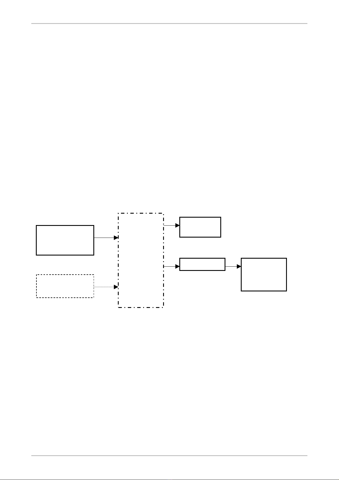
The most sensitive and accurate pre-correction is achieved by doing the adjustments while observing the intermodulation products at all
amplitude levels of the vision carrier, suitably demodulated from an R.F. sample taken at the output of the R.F. amplifier. The video
carrier is modulated with a grey staircase signal, complete with the chrominance signal. If intermodulation is low and the intermodulation
products are hardly visible, something which may happen, depending also on the test instrumentation, a second sound carrier can be
added using the SOUND 2 input of the Vision Modulator plug-in.
chrominance signal
Video Measurement
Set.
VM 700
or equivalent
R.F. Demodulator
Dummy Load
TV Transmitter
under test
ADJUSTMENTS:
K1-S1-PH1
K2-S2-PH2
K3-S3-PH3
Second Sound Carrier
Generator. (Only if
necessary)
Video Signal Generator.
Staircase with
Figure 11: Blocks diagram for pre-correction set-up of TV Transmitters
With reference to blocks diagram above:
• Connect a Video Signal Generator at the video input (#1) of the Exciter.
• Connect the output of the Transmitter (Exciter alone, or Exciter + R.F. Amplifier, in case of composite units) to a dummy load.
• Connect the R.F. MONITOR output of the Exciter, or of the R.F. Amplifier, to the Demodulator.
• Connect the output of the Demodulator to a Video Measurement Set, such as, for example, the Tektronix VM700, or to another
analogue Waveform Monitor. It is essential that the Video Measurement Set be equipped with a Differential Step Filter, as this
device enhances the display of the intermodulation products that have to be minimised.
NOTE: If the Transmitter was factory aligned on the same channel and for the same R.F. power output, only a small touch-up of
trimmers K1, K2 and K3 is required. A small correction will also be needed after the replacement of a faulty R.F. device, and/or for a
small frequency change, and/or for change in R.F. power output. In these cases, it will not be necessary to extract the MODM33 plug-in
to gain access to the internal trimmers.
Nov 02 CMAN0310ENG 19
Table of contents
Other EuroTel Transmitter manuals


Popular Transmitter manuals by other brands

Baker Hughes
Baker Hughes Panametrics HygroPro user manual

Sennheiser
Sennheiser SR 2000 IEM Brochure & specs

BBC Bircher
BBC Bircher XRF-T.2 Original operating instructions

Yamaha
Yamaha YIT-W12 owner's manual

Omnitronic
Omnitronic TM-1000 operating instructions

GPS
GPS GPS-FC-3T-BAS Installation, operation & maintenance manual


