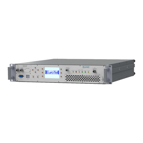
EuroTel ETLU4G03 User manual


ETLU4G03 Rev. 003
Page 2 CMANU4G03 Jul 2013

Rev. 003 ETLU4G03
Operating an Technical Manual
Operating an Technical ManualOperating an Technical Manual
Operating an Technical Manual
2 kW (RMS) DTV / 5 kW ATV
2 kW (RMS) DTV / 5 kW ATV 2 kW (RMS) DTV / 5 kW ATV
2 kW (RMS) DTV / 5 kW ATV
UHF B IV-V RF AIR-COOLED TV TRANSMITTER ETLU4G03
UHF B IV-V RF AIR-COOLED TV TRANSMITTER ETLU4G03UHF B IV-V RF AIR-COOLED TV TRANSMITTER ETLU4G03
UHF B IV-V RF AIR-COOLED TV TRANSMITTER ETLU4G03
TABLE OF CONTENTS
TABLE OF CONTENTSTABLE OF CONTENTS
TABLE OF CONTENTS
Section A- GENERAL INFORMATION..............................................................................................5
I - AMENDMENT RECORD SHEET............................................................................................5
II - APPROVAL RECORD SHEET................................................................................................5
Section B- SAFETY INSTRUCTIONS...............................................................................................6
1 ) GENERAL INSTRUCTIONS...........................................................................................6
2 ) AC LINE HAZARDS......................................................................................................6
3 ) RF HAZARDS...............................................................................................................7
4 ) FIRE RISK....................................................................................................................7
5 ) HANDLING BERYLLIUM OXIDE CERAMICS..................................................................7
6 ) FIRST AID IN CASE OF ELECTRIC SHOCK....................................................................8
7 ) EMERGENCY RESUSCITATION: EXPIRED AIR METHOD................................................8
8 ) TREATMENT FOR BURNS.............................................................................................8
Section C- SYSTEM DESCRIPTION, INSTALLATION AND TECHNICAL SPECIFICATIONS.......10
I - INTRODUCTION................................................................................................................10
II - FUNCTIONAL DESCRIPION................................................................................................10
III - ENERGY DISTRIBUTION AND COOLING...........................................................................12
IV - THEORY OF OPERATION OF ETLU4G03 TV TRANSMITTER ...............................................13
V - COMPOSITION OF ETLU4G03 TV TRANSMITTER ..............................................................14
VI - INSTALLATION OF ETLU4G03 TV TRANSMITTER................................................................15
1 ) ETLU4G03 TV Transmitter: connections an mo ule installation....................................15
2 ) Other connections.......................................................................................................15
3 ) First time operation of ETLU4G03................................................................................16
VII - TECHNICAL SPECIFICATIONS OF ETLU4G03 TV TRANSMITTER........................................18
1 ) General......................................................................................................................18
2 ) Output Parameters......................................................................................................18
3 ) Linear istortion..........................................................................................................18
4 ) Non linear istortion...................................................................................................18
Section D- MAINTENANCE & ALIGNMENT INSTRUCTIONS........................................................19
I - ETLU4G03 TRANSMITTER UNIT...........................................................................................19
1 ) Changing R.F. Output Power of the transmitter unit.......................................................19
2 ) Replacement an configuration of ETL0474G R.F. Amplifier mo ule.............................20
Section E- WEB INTERFACE............................................................................................................22
1 ) Summary WEB page...................................................................................................23
2 ) Supervisor WEB page..................................................................................................24
3 ) Log page....................................................................................................................25
4 ) Amplifier page............................................................................................................26
5 ) GSM (option) WEB page..............................................................................................27
Section F- LAYOUT ASSEMBLY AND CIRCUIT DIAGRAMS.........................................................29
I - MAINFRAME AND WIRING DIAGRAM..................................................................................29
1 ) ETLU4G03 WIRING DIAGRAM....................................................................................29
II - MAINS TRANSFORMER AND ENERGY DISTRIBUTION..........................................................31
1 ) Schematic iagram.....................................................................................................31
Jul 2013 CMANU4G03 Page 3
33
3

ETLU4G03 Rev. 003
TABLE OF ILLUSTRATIONS
TABLE OF ILLUSTRATIONSTABLE OF ILLUSTRATIONS
TABLE OF ILLUSTRATIONS
Figure 1: ETLU4G03 TV Transmitter – front view..........................................................................11
Figure 2: ETL0474G R.F. Amplifier module – rear view................................................................12
Figure 3: ETLU4G03 TV TRANSMITTER - functional blocks diagram........................................13
Figure 4: WEB interface: RF Output page......................................................................................19
Figure 5: WEB interface: Login page..............................................................................................22
Figure 6: WEB interface - Summary page.......................................................................................23
Figure 7: WEB interface: Supervisor page.....................................................................................24
Figure 8: WEB interface: Log page.................................................................................................25
Figure 9: WEB interface: Amplifier page........................................................................................26
Figure 10: WEB interface - GSM page.............................................................................................27
Page 4 CMANU4G03 Jul 2013

Rev. 003 ETLU4G03
Section A-
Section A-Section A-
Section A-GENERAL INFORMATION
GENERAL INFORMATIONGENERAL INFORMATION
GENERAL INFORMATION
I -
I - I -
I - AMENDMENT RECORD SHEET
AMENDMENT RECORD SHEETAMENDMENT RECORD SHEET
AMENDMENT RECORD SHEET
When an amen ment to this publication is incorporate , the recor below is to be complete an
initiale .
Release
ReleaseRelease
Release Language
LanguageLanguage
Language DESCRIPTION
DESCRIPTIONDESCRIPTION
DESCRIPTION AUTHORITY
AUTHORITYAUTHORITY
AUTHORITY DATE
DATEDATE
DATE
II -
II - II -
II - APPROVAL RECORD SHEET
APPROVAL RECORD SHEETAPPROVAL RECORD SHEET
APPROVAL RECORD SHEET
When an approval to this publication is incorporate , the recor below is to be complete .
Release
ReleaseRelease
Release Signature
SignatureSignature
Signature AUTHORITY
AUTHORITYAUTHORITY
AUTHORITY DATE
DATEDATE
DATE
© EUROTEL S.p.A.
© EUROTEL S.p.A.© EUROTEL S.p.A.
© EUROTEL S.p.A.
The inform tion cont ined herein is the property of EUROTEL S.p.A. nd is supplied without li bility
The inform tion cont ined herein is the property of EUROTEL S.p.A. nd is supplied without li bility The inform tion cont ined herein is the property of EUROTEL S.p.A. nd is supplied without li bility
The inform tion cont ined herein is the property of EUROTEL S.p.A. nd is supplied without li bility
for errors or omissions nd no p rt m y be reproduced, used or disclosed, except s uthorized by
for errors or omissions nd no p rt m y be reproduced, used or disclosed, except s uthorized by for errors or omissions nd no p rt m y be reproduced, used or disclosed, except s uthorized by
for errors or omissions nd no p rt m y be reproduced, used or disclosed, except s uthorized by
contr ct or other written permission. The copyright nd the foregoing restriction on reproduction, use
contr ct or other written permission. The copyright nd the foregoing restriction on reproduction, use contr ct or other written permission. The copyright nd the foregoing restriction on reproduction, use
contr ct or other written permission. The copyright nd the foregoing restriction on reproduction, use
nd disclosure extends to ll medi in which this inform tion m y be embodied, including m gnetic
nd disclosure extends to ll medi in which this inform tion m y be embodied, including m gnetic nd disclosure extends to ll medi in which this inform tion m y be embodied, including m gnetic
nd disclosure extends to ll medi in which this inform tion m y be embodied, including m gnetic
or electronic stor ge, etc.
or electronic stor ge, etc.or electronic stor ge, etc.
or electronic stor ge, etc.
Jul 2013 CMANU4G03 Page 5
55
5

ETLU4G03 Rev. 003
Section B-
Section B-Section B-
Section B-SAFETY INSTRUCTIONS
SAFETY INSTRUCTIONSSAFETY INSTRUCTIONS
SAFETY INSTRUCTIONS
1 )
1 ) 1 )
1 ) GENERAL INSTRUCTIONS
GENERAL INSTRUCTIONSGENERAL INSTRUCTIONS
GENERAL INSTRUCTIONS
Observe the following safety precautions when han ling this unit. This equipment operates with
angerous voltages an currents.
•All electrical installations an connections are to be carrie out only by skille personnel.
•When outfitting operating rooms as well as setting up an operating electrical equipment follow the
relevant national an international safety instructions an regulation.
•When setting up the rack observe the relevant safety precautions for the prevention of acci ents.
These precautions especially relate to: anger of getting crushe when working with loa s, anger of
falling off la ers while working, anger of getting hurt or injure when lifting heavy loa s.
•Always isconnect power before opening covers or removing any part or mo ule of this transmitter
unit.
•Prior to checking out or working on the switch mo e supply, isconnect all the R.F. power amplifiers.
•Some of the R.F. power amplifier transistors are encase in Beryllium Oxi e (BeO). This substance is
harmless as is, but becomes very angerous if groun to a pow er. These evices, once faile ,
cannot be ispose of by normal means an special proce ures of isposal must be observe .
•In any case, but especially when the RF Power Amplifier is operating,
In any case, but especially when the RF Power Amplifier is operating, In any case, but especially when the RF Power Amplifier is operating,
In any case, but especially when the RF Power Amplifier is operating, o not attempt
o not attempto not attempt
o not attempt to remove
to remove to remove
to remove
an then re-insert the rear panel coaxial interconnecting cables of the EXCITER. Although suitable
an then re-insert the rear panel coaxial interconnecting cables of the EXCITER. Although suitable an then re-insert the rear panel coaxial interconnecting cables of the EXCITER. Although suitable
an then re-insert the rear panel coaxial interconnecting cables of the EXCITER. Although suitable
protection circuitry is in place, su en loss an re-application of RF rive causes transients that
protection circuitry is in place, su en loss an re-application of RF rive causes transients that protection circuitry is in place, su en loss an re-application of RF rive causes transients that
protection circuitry is in place, su en loss an re-application of RF rive causes transients that
may amage one or more RF amplification stages.
may amage one or more RF amplification stages.may amage one or more RF amplification stages.
may amage one or more RF amplification stages.
2 )
2 ) 2 )
2 ) AC LINE HAZARDS
AC LINE HAZARDSAC LINE HAZARDS
AC LINE HAZARDS
Voltage values Vrms > 30V AC or V > 60V DC are potential hazar . Take appropriate measures to
avoi any anger when working with hazar ous voltages.
Never work on live parts. It is only permissible to work on live parts un er exceptional circumstance an
if special safety precautions have been taken.
Power Supply
Power SupplyPower Supply
Power Supply
Prior to connecting power supply ensure that the AC line ata on the pro uct matches the ata of the
available supply. Fuses or other evices in the supply circuit must guarantee overloa an short-circuit
protection.
The user is responsible for correct fuse protection.
Emergency off
Emergency offEmergency off
Emergency off
On the front panel the transmitter is equippe with an emergency push-button that open the power
mains circuit when enable turning off the transmitter unit.
Page 6 CMANU4G03 Jul 2013

Rev. 003 ETLU4G03
Replacement of fuses
Replacement of fusesReplacement of fuses
Replacement of fuses
The transmitter fuses accessible in the operator area may be replace with the transmitter turne off.
They shoul be replace only by fuses with the same electrical specifications
The protective switches accessible in the operator area may be actuate . If their response range can be
a juste , the setting performe by the manufacturer shoul not be mo ifie .
3 )
3 ) 3 )
3 ) RF HAZARDS
RF HAZARDSRF HAZARDS
RF HAZARDS
In the transmitter, high-energy RF circuits are fe through common RF connectors (eg N). Depen ing on
the output power, the transmitter outputs are fitte with screw-in RF lines or wavegui es.
CAUTION!
CAUTION!CAUTION!
CAUTION!
•Never unscrew RF lines when the transmitter is in operation.
•Never open mo ules when the transmitter is in operation.
If RF lines which are in operation are isconnecte , electric arcs may be generate an cause burns an
eye injuries.
•Never put the transmitter into operation when RF lines are open-circuite .
4 )
4 ) 4 )
4 ) FIRE RISK
FIRE RISKFIRE RISK
FIRE RISK
There is a risk of fire presente by any live electrical if there is sufficient energy conversion which is the
case with ra io transmitters.
Preventive measures on-site can re uce fire hazar s to a large extent an effectively re uce the fire
sprea ing.
CAUTION!
CAUTION!CAUTION!
CAUTION!
•On installing the transmitter, the user shall ensure that no combustible materials are store ro fitte
beneath or above the cable entry.
Firefighting must be performe only with special equipment (eg breathing apparatus with air bottle) in
or er to avoi inhalation of harmful fumes, gases an ust pro uce by combustion.
5 )
5 ) 5 )
5 ) HANDLING BERYLLIUM OXIDE CERAMICS
HANDLING BERYLLIUM OXIDE CERAMICSHANDLING BERYLLIUM OXIDE CERAMICS
HANDLING BERYLLIUM OXIDE CERAMICS
Parts containing BeO ceramics are not a health hazar provi e that safety regulations are followe .
CAUTION!
CAUTION!CAUTION!
CAUTION!
Parts ma e from BeO ceramics shall not be machine , score , crushe , broken, heate nor
san blaste . BeO ust passes through all common filtering system inclu ing conventional apparatus
filters.
Parts ma e from BeO ceramics shall not be opene nor estroye .
Jul 2013 CMANU4G03 Page 7
77
7

ETLU4G03 Rev. 003
6 )
6 ) 6 )
6 ) FIRST AID IN CASE OF ELECTRIC SHOCK
FIRST AID IN CASE OF ELECTRIC SHOCKFIRST AID IN CASE OF ELECTRIC SHOCK
FIRST AID IN CASE OF ELECTRIC SHOCK
DO NOT TOUCH THE VICTIM WITH YOUR BARE HANDS until the circuit is broken. SWITCH OFF. If this
is not possible, PROTECT YOURSELF with DRY insulating material an pull the victim clear of the
con uctor. If breathing has stoppe , in icate by unconsciousness, lack of respiratory movements an a
‘blue’ look to cheeks, lips, ears an nails, START RESUSCITATION AT ONCE.
7 )
7 ) 7 )
7 ) EMERGENCY RESUSCITATION: EXPIRED AIR METHOD
EMERGENCY RESUSCITATION: EXPIRED AIR METHODEMERGENCY RESUSCITATION: EXPIRED AIR METHOD
EMERGENCY RESUSCITATION: EXPIRED AIR METHOD
•If possible, lie the victim on his back, with his hea slightly higher than his
feet. Clear the mouth an the throat of any obvious obstruction.
•Kneel on one si e of the victim, level with his hea . LIFT THE JAW AND
TILT THE HEAD BACK AS FAR AS POSSIBLE. (Figures 1a an 1b).
•One of the following may now happen:
⇒Breathing may begin an consciousness return.
⇒Breathing may begin, but consciousness may NOT return. Turn the
victim on his si e an ensure that the airway is kept clear.
⇒Breathing may return, but be NOISY, which means that the airway is
not fully clear. Try to clear the airway.
•IF THERE IS NO SIGN OF BREATHING
⇒Check that the hea is still tilte back.
⇒Take a eep breath.
⇒Pinch the victim’s nose an blow firmly into his mouth. As you o, his
chest will RISE (figure 2).
⇒Turn your hea away an take another breath, watching for the chest
to FALL (figure 3).
•Start with four quick eep breaths an then continue with one breath every
five secon s (i.e. 12 times a minute). This shoul be continue until the
victim revives or a octor certifies eath.
•As consciousness returns, the victim will start to breathe on his own an a
‘pink’ color replaces the ‘blue’ look. This is the time to stop resuscitation.
Continue to hol his chin up an so keep the airway clear.
•In the case of injuries to the mouth, it may be necessary to use mouth-to-
nose resuscitation. Seal the victim’s mouth with your cheek an blow firmly
into his nose, procee ing as above.
•In any case it is ESSENTIAL to commence resuscitation WITHOUT DELAY an to sen for me ical
assistance imme iately.
8 )
8 ) 8 )
8 ) TREATMENT FOR BURNS
TREATMENT FOR BURNSTREATMENT FOR BURNS
TREATMENT FOR BURNS
If the victim is also suffering from burns, then, without hin rance to resuscitation, observe the following:
•Do not ttempt to remove clothing dhering to the burns.
Do not ttempt to remove clothing dhering to the burns.Do not ttempt to remove clothing dhering to the burns.
Do not ttempt to remove clothing dhering to the burns.
Page 8 CMANU4G03 Jul 2013

Rev. 003 ETLU4G03
•If possible, alleviate the pain from the burn part by immersing in col water.
•If help is available or as soon as resuscitation is no longer require , the woun shoul be covere
with a DRY clean ressing.
•If help is available or as soon as resuscitation is no longer require , the woun shoul be covere
with a DRY clean ressing.
Jul 2013 CMANU4G03 Page 9
99
9

ETLU4G03 Rev. 003
Section C-
Section C-Section C-
Section C-SYSTEM DESCRIPTION, INSTALLATION AND
SYSTEM DESCRIPTION, INSTALLATION AND SYSTEM DESCRIPTION, INSTALLATION AND
SYSTEM DESCRIPTION, INSTALLATION AND
TECHNICAL SPECIFICATIONS
TECHNICAL SPECIFICATIONSTECHNICAL SPECIFICATIONS
TECHNICAL SPECIFICATIONS
I -
I - I -
I - INTRODUCTION
INTRODUCTIONINTRODUCTION
INTRODUCTION
•The series ETLU4G03 TV Transmitter provi es linear, class “AB” amplification of R.F. TV signal in
the stan ar UHF ban s IV & V (470 to 860MHz).
•ETLU4G03 is esigne to work both in DTV mo e an ATV mo e.
•Rate R.F. output power is set to 2kW (rms) for DTV mo e an 5kW peak sync for ATV mo e.
•The use of high efficiency, high power gain LDMOS power transistors allows to obtain highly
efficient amplifier mo ules as ETL0474G.
•The ETLU4G03 is air-coole . Air cooling system inclu es three internal blowers place behin the
front panel of each ETL0474G amplifier mo ule. An a itional large iameter fan place on the
roof of the transmitter extracts the hot air from the transmitter rack. In this way a high re un ancy of
the cooling system is obtaine .
II -
II - II -
II - FUNCTIONAL DESCRIPION
FUNCTIONAL DESCRIPIONFUNCTIONAL DESCRIPION
FUNCTIONAL DESCRIPION
•The main transmitter components are:
⇒transmitter rack with built in isolation mains transformer an power istribution,
⇒ual rive exciter with changeover or single rive exciter,
⇒power splitters,
⇒R.F. amplifier mo ules,
⇒power combiner,
⇒output ban -pass filter or external combiner both as an option.
•The exciter mo ulates the analog vi eo an au io signals or igital MPEG-2 ASI ata inputs onto
the set channel frequency, provi ing pre-correction circuit that ensures linear transmission with the
minimum intermo ulation pro ucts.
•The power splitters istributes the output power of the exciter to the R.F. amplifier mo ules.
The R.F. broa ban amplifier mo ules provi e linear, class “AB” amplification of composite
Vision+Soun TV signals, an are compatible with igital TV stan ar s DVB-T/H, DVB-T2, ATSC.
•A power combiner combines the output power of the R.F. amplifier mo ules to the total transmitter
output power.
•A ban -Pass filter (option) is installe before the output irectional coupler for the suppression of the
out of ban interferences.
Page 10 CMANU4G03 Jul 2013


ETLU4G03 Rev. 003
III -
III - III -
III - ENERGY DISTRIBUTION AND COOLING
ENERGY DISTRIBUTION AND COOLINGENERGY DISTRIBUTION AND COOLING
ENERGY DISTRIBUTION AND COOLING
•At the bottom of the cabinet a three phase isolation transformer provi es:
⇒lightning protection an isolation from mains
⇒single phase 230V current to supply exciters, supervisor units with change-over logic an
blower
⇒three phase 57V current to supply R.F. amplifier mo ules
•The primary si e of the mains transformer is protecte by an automatic breakers use to switch on
an off the transmitter.
•The electric current from the secon ary si e of the transformer is istribute to each R.F. amplifier
mo ule by an in ivi ual secon ary win ing an an in ivi ual automatic breaker. So each amplifier
mo ule can be in ivi ually switche on an off.
•A secon ary win ing an an automatic breaker are e icate to supply electric current to Exciters
an supervisor mo ule of the Transmitter unit.
•Three blowers are place internally in each R.F. amplifier an a large iameter blower is locate on
the roof of the cabinet to extract the exhaust air from the rack.
Figure 2: ETL0474G R.F. Amplifier module – re r view
Page 12 CMANU4G03 Jul 2013
3-PHASE
57V CURRENT
INPUT
R.F. POWER
OUTPUT

Rev. 003 ETLU4G03
IV -
IV - IV -
IV - THEORY OF OPERATION OF
THEORY OF OPERATION OF THEORY OF OPERATION OF
THEORY OF OPERATION OF ETLU4G03
ETLU4G03 ETLU4G03
ETLU4G03 TV TRANSMITTER
TV TRANSMITTER TV TRANSMITTER
TV TRANSMITTER
•With reference to the general blocks iagram shown in Figure 3, the output signal from the Exciter
reaches the input low power ivi er which splits the rive signal into three components. This system
incorporates a step attenuator an a step phase shifter to balance the slight gain an phase
ifferences of R.F. Amplifiers. The resultant signals rive the three
ETL0474G
R.F. Amplifiers. The
Output power combiner at the outputs of the three R.F. Amplifiers combines the output signals to a
nominal level of 2kWrms.
Figure 3: ETLU4G03 TV TRANSMITTER - function l blocks di gr m
Jul 2013 CMANU4G03 Page 13
1313
13

ETLU4G03 Rev. 003
•At the en of the R.F. output line, a irectional coupler collects samples of forwar & reflecte output
power, which are sent to the ETL0700TA Transmitter Supervisor & Controller.
•The ETL0700TA controller is use in the transmitter system to monitor an control all amplifier
parameters an to allow the ata exchange between the transmitter an an external control via the
serial ports RS232 an RS485.
•The ETL0700TA mo ule executes the following functions:
⇒Monitors the Forwar output power
⇒Monitors the reflecte power an generates the “antenna VSWR alarm” comman
⇒Monitors the output power an all parameters of all the amplifier mo ules
⇒Controls the enable of the amplifiers an of the exciter
⇒Establishes ata communication of the transmitter with an external control via the RS232
an RS485 serial port
•Through a “CAN BUS” line name serial E-LINK the controller mo ule establishes a bi irectional
communication with the amplifier mo ules.
Shoul one of the R.F. amplifier mo ules enters in alarm status, the controller will sen a comman
to all the other amplifiers that will consequently enter into the warning state lowering the supply
voltage by 10%.
•TX Mo e: ETL3100 TV Exciter Device configuration (DVB-T/H, DVB-T2, ISDB-T, ATSC, Analog TV,
Transposer an DVB-T Remo ulator) etermines analog or igital transmission mo e. The exciter
also sen s this information to the supervisor by an E-Link bus remote control message. The
supervisor sen s the same information to the R.F. amplifier mo ules.
V -
V - V -
V - COMPOSITION OF
COMPOSITION OF COMPOSITION OF
COMPOSITION OF ETLU4G03 TV TRANSMITTER
ETLU4G03 TV TRANSMITTERETLU4G03 TV TRANSMITTER
ETLU4G03 TV TRANSMITTER
•ETLU4G03 TV Transmitter comprises three ETL0474G R.F. Amplifiers, one (two as option) Exciter,
one Transmitter Supervisor & controller, one input power ivi er, one output R.F. power combiner,
50 Ohm balancing loa for the combiner an one ban -pass filter (option) for the attenuation of
harmonics an out of ban pro ucts. All these parts are assemble into one stan ar cabinet
600x1000x2100mm. The list of stan ar parts is as follows.
PARTS SUPPLIED IN THE STANDARD CONFIGURATION
PARTS SUPPLIED IN THE STANDARD CONFIGURATIONPARTS SUPPLIED IN THE STANDARD CONFIGURATION
PARTS SUPPLIED IN THE STANDARD CONFIGURATION QTY
QTYQTY
QTY MO
MOMO
MO
R.F. Amplifiers 3 ETL0474G
Transmitter supervisor & controller 1 ETL0700TA
TV Exciter 1 or 2 ETL3100
Input power splitter 1 MODM244
Output power combiner 1 MC3Q60C
50 Ohm high power balancing loa 1
Output irectional coupler 1
Output ban pass filter / combiner (both as an option) 1
Stan ar rack 40 Unit cabinet 1
Page 14 CMANU4G03 Jul 2013

Rev. 003 ETLU4G03
VI -
VI - VI -
VI - INSTALLATION
INSTALLATION INSTALLATION
INSTALLATION OF ETLU4G03 TV TRANSMITTER
OF ETLU4G03 TV TRANSMITTEROF ETLU4G03 TV TRANSMITTER
OF ETLU4G03 TV TRANSMITTER
1 )
1 ) 1 )
1 ) ETLU4G03 TV Transmitter: connections an mo ule installation
ETLU4G03 TV Transmitter: connections an mo ule installationETLU4G03 TV Transmitter: connections an mo ule installation
ETLU4G03 TV Transmitter: connections an mo ule installation
Prior to installing the Transmitter unit check whether the floor of the transmitter buil ing can take the
weight. The floor surface shoul be plane (i.e. parallel with any horizontal si e).
CAUTION:
CAUTION:CAUTION:
CAUTION:
Because of the weight of the transmitter rack(s) use a equate tools for raising an transport.
The ETLU4G03 transmitter unit is shippe isassemble in a series of main blocks. To assemble an
install the Transmitter unit follow the steps below.
For R.F./electrical connections also refer to “MAINFRAME AND WIRING DIAGRAM” provi e with
For R.F./electrical connections also refer to “MAINFRAME AND WIRING DIAGRAM” provi e with For R.F./electrical connections also refer to “MAINFRAME AND WIRING DIAGRAM” provi e with
For R.F./electrical connections also refer to “MAINFRAME AND WIRING DIAGRAM” provi e with
operating an technical manual of the Transmitter unit.
operating an technical manual of the Transmitter unit.operating an technical manual of the Transmitter unit.
operating an technical manual of the Transmitter unit.
•Connect R.F. output coaxial line to antenna.
•Install the R.F. Amplifier mo ules i entifie by means of marking stickers on the mo ules, in their
spaces also marke with correspon ing stickers paste on the insi e wall of the cabinet.
•Install the Exciters in the apposite space in the cabinet.
•The Transmitter Supervisor & Controller is alrea y fitte in the cabinet.
•Connect all cables supplie an alrea y wire in the cabinet. In or er to simplify this operation,
every cable has stickers at each en .
•Connect A.C. mains cables coming from the Mains Distribution Mo ule installe at the bottom of
the cabinet, to all mo ule of the Transmitter unit.
•Check again the correct connection of R.F. coaxial lines.
•Ensure the stability of the transmitter unit by means of the extensible feet provi e . Exten the feet
until they will be in contact with the floor an they hol uniformly the entire weight of the rack.
Check with a spirit level to ensure that the rack is vertical on all si es.
•The Prime Power line connection is preset for a 3-phase 400V nominal prime power line (other
Prime Power line connection are on request).
•Prime power line connection:
Connect the groun ro terminal to groun an the R, S, T terminal to the 3-Phase mains.
2 )
2 ) 2 )
2 ) Other connections
Other connectionsOther connections
Other connections
•The ETLU4G03 make available external alarm connections by means of har wire an insulate
relay contacts. A itionally, all significant operating parameters are provi e on a stan ar RS-232
an RS-485 interface.
•To wire the relay contacts to external circuits use the ALARMS OUT socket.
Jul 2013 CMANU4G03 Page 15
1515
15

ETLU4G03 Rev. 003
3 )
3 ) 3 )
3 ) First time operation of ETLU4G03
First time operation of ETLU4G03First time operation of ETLU4G03
First time operation of ETLU4G03
ETLU4G03 is shippe with all the main switches set in the correct configuration. So when the Transmitter
is connecte to mains network it will be turne off.
Prior to switch on the transmitter ensure that all R.F. connections have been carrie out properly.
Prior to switch on the transmitter ensure that all R.F. connections have been carrie out properly.Prior to switch on the transmitter ensure that all R.F. connections have been carrie out properly.
Prior to switch on the transmitter ensure that all R.F. connections have been carrie out properly.
Check for vi eo mo ulation signal presence prior to start with switch on proce ure.
Once the Transmitter unit is properly installe follow the steps below for the first time operation.
•Turn on “Main Supply” switch of the Transmitter unit. Three phase monitor LEDS of each Block
shoul switch on showing three phases presence.
•Turn on “Internal Single Phase” switch of the Transmitter unit. This switch provi es power supply to
230V a.c. internal mo ules of the Transmitter unit (Exciters, Transmitter Supervisor & Controller,
internal cooling blowers).
•Turn on “Amplifier” switches of the Transmitter unit. These switches provi e power supply to amplifier
mo ules of the Transmitter unit. Each amplifier has its own switch so each amplifier mo ule can be
turne off in ivi ually.
•Turn on the “On/Off” switch on the front panel of each Exciter.
Now the Transmitter unit is completely switche on. The isplay of each mo ule shoul be operating.
•Make sure there are no alarm status for the Transmitter unit.
•Check that exciter mo ules are set in “Local” mo e an in “Off” status.
Now is possible to enable R.F. output power from the Transmitter unit.
•Enable R.F. output power of the Transmitter unit by means of “TX On” comman on Transmitter
Supervisor & Controller unit.
Refer also to “ETL0700TA Transmitter Supervisor & Controller Operating an Technical Manual” for
Refer also to “ETL0700TA Transmitter Supervisor & Controller Operating an Technical Manual” for Refer also to “ETL0700TA Transmitter Supervisor & Controller Operating an Technical Manual” for
Refer also to “ETL0700TA Transmitter Supervisor & Controller Operating an Technical Manual” for
Supervisor comman explanation.
Supervisor comman explanation.Supervisor comman explanation.
Supervisor comman explanation.
•By means of Transmitter Supervisor & Controller, set “TX Exciter A On/Off” an “TX Exciter B
On/Off” to “On” or “Off” accor ing to the actual position of the changeover switch. Changeover
position is shown in Transmitter Supervisor & Controller main page.
•Set the on-air exciter (exciter selecte to be “on-air” by changeover switch) to “On” status by means
of the soft key of the exciter mo ule.
For safety reasons the Transmitter unit is factory set in or er to provi e very low level of R.F. output
For safety reasons the Transmitter unit is factory set in or er to provi e very low level of R.F. output For safety reasons the Transmitter unit is factory set in or er to provi e very low level of R.F. output
For safety reasons the Transmitter unit is factory set in or er to provi e very low level of R.F. output
power at the first time operation.
power at the first time operation.power at the first time operation.
power at the first time operation.
To set the nominal R.F. output level follow the steps below. The following proce ure must be followe to
The following proce ure must be followe toThe following proce ure must be followe to
The following proce ure must be followe to
make sure that all the R.F. connections are properly one.
make sure that all the R.F. connections are properly one.make sure that all the R.F. connections are properly one.
make sure that all the R.F. connections are properly one.
Refer also to “ETL3100RT Operating an Technical Manual” for Exciter comman explanation.
Refer also to “ETL3100RT Operating an Technical Manual” for Exciter comman explanation.Refer also to “ETL3100RT Operating an Technical Manual” for Exciter comman explanation.
Refer also to “ETL3100RT Operating an Technical Manual” for Exciter comman explanation.
•Check again vi eo mo ulation signal presence.
Page 16 CMANU4G03 Jul 2013

Rev. 003 ETLU4G03
•On the on-air exciter, exciter selecte by changeover switch, increase “RF Output level” by 3 B steps
checking each time that no reflecte transmission power occurs.
•Continue to increase “RF out level” until 0 B level is reache . Increasing RF Output level remember
Increasing RF Output level rememberIncreasing RF Output level remember
Increasing RF Output level remember
to pay attention to reflecte output power of the Transmitter
to pay attention to reflecte output power of the Transmitterto pay attention to reflecte output power of the Transmitter
to pay attention to reflecte output power of the Transmitter.
•Once 0 B RF Out level is reache , R.F. output power of the Transmitter shoul assume a value close
to the nominal level expecte .
•On the on-air exciter enable A.L.C. control. Set “
A.L.C. config
A.L.C. configA.L.C. config
A.L.C. config
” to “
External
ExternalExternal
External
” in the menu “RF output”
of the exciter mo ule.
Now the R.F. output power of the transmitter will assume the correct nominal level expecte .
•Set the 0 B RF Out level an A.L.C control to “External
ExternalExternal
External” on the other Exciter mo ule (exciter mo ule
that isn't selecte by changeover switch).
•Set both Exciter mo ules in “Remote
RemoteRemote
Remote” mo e.
•Set the Transmitter Supervisor & Controller mo ule in “Auto
AutoAuto
Auto” an “Remote
RemoteRemote
Remote” mo e.
VERIFING SAFETY PUSH-BUTTON:
Actuating the EPO safety push-button the Transmitter unit MUST be completely turne off. All units will be
insulate from their power supply sources.
Remember to isable EPO push-button an to restore Transmitter unit automatic breakers after that
Remember to isable EPO push-button an to restore Transmitter unit automatic breakers after that Remember to isable EPO push-button an to restore Transmitter unit automatic breakers after that
Remember to isable EPO push-button an to restore Transmitter unit automatic breakers after that
EPO operation has been carrie out.
EPO operation has been carrie out.EPO operation has been carrie out.
EPO operation has been carrie out.
Jul 2013 CMANU4G03 Page 17
1717
17

ETLU4G03 Rev. 003
VII -
VII - VII -
VII - TECHNICAL SPECIFICATIONS OF ETLU4G03 TV TRANSMITTER
TECHNICAL SPECIFICATIONS OF ETLU4G03 TV TRANSMITTERTECHNICAL SPECIFICATIONS OF ETLU4G03 TV TRANSMITTER
TECHNICAL SPECIFICATIONS OF ETLU4G03 TV TRANSMITTER
1 )
1 ) 1 )
1 ) General
GeneralGeneral
General
Primary power 220 V Single-phase. +15% -15% 47 to 60 Hz
400 V 3-phase. +15% -15% 47 to 60 Hz
Cooling Force -air
Operating temperature range -5°C to +45°C.
Storage temperature range -10 to +70°C.
2 )
2 ) 2 )
2 ) Output Parameters
Output ParametersOutput Parameters
Output Parameters
Output frequency range BANDS IV-V: 470-860MHz.
Stan ar Output Power 2000 Wrms ±0,3 B DVB-T, DVB-T2
5000 Wp.s. ±0,3 B ATV
Permissible VSWR < 1,4
Frequency stability
(without external reference)
±100 Hz/year.
2
n
harmonic suppression -40 B before filter.
3
r
harmonic suppression -40 B before filter.
Intermo ulation at transmitter
output (shoul ers before filter)
> 36 B.
3 )
3 ) 3 )
3 ) Linear istortion
Linear istortionLinear istortion
Linear istortion
Amplitu e error ≤ 0,5 B.
Group elay error ≤ 100 ns.
4 )
4 ) 4 )
4 ) Non linear istortion
Non linear istortionNon linear istortion
Non linear istortion
MER rms >36 B.
Page 18 CMANU4G03 Jul 2013

Rev. 003 ETLU4G03
Section D-
Section D-Section D-
Section D-MAINTENANCE & ALIGNMENT
MAINTENANCE & ALIGNMENT MAINTENANCE & ALIGNMENT
MAINTENANCE & ALIGNMENT
INSTRUCTIONS
INSTRUCTIONSINSTRUCTIONS
INSTRUCTIONS
I -
I - I -
I - ETLU4G03 TRANSMITTER UNIT
ETLU4G03 TRANSMITTER UNITETLU4G03 TRANSMITTER UNIT
ETLU4G03 TRANSMITTER UNIT
1 )
1 ) 1 )
1 ) Changing R.F. Output Power of the transmitter unit.
Changing R.F. Output Power of the transmitter unit.Changing R.F. Output Power of the transmitter unit.
Changing R.F. Output Power of the transmitter unit.
The R.F. Output Power of the transmitter unit can be change both in local mo e working on in place
transmitter unit an in remote mo e via the WEB interface.
Changing the R.F. Output Power in remote mo e via WEB interface:
Changing the R.F. Output Power in remote mo e via WEB interface:Changing the R.F. Output Power in remote mo e via WEB interface:
Changing the R.F. Output Power in remote mo e via WEB interface:
To change the R.F. Output Power in remote mo e via web interface follow the steps below:
•Connect to the exciter WEB page using the relate IP a ress.
•Insert the “Username” an the “Passwor ” in the login WEB page an press “Login” button.
•Select “RF Output” page from the list place on the left si e of the WEB page.
•Change the “Extrernal ALC ref power” accor ing to the esire R.F. Output power an press “Apply
Changes” button.
Figure 4: WEB interf ce: RF Output p ge
Jul 2013 CMANU4G03 Page 19
1919
19

ETLU4G03 Rev. 003
Changing the R.F. Output Power in local mo e:
Changing the R.F. Output Power in local mo e:Changing the R.F. Output Power in local mo e:
Changing the R.F. Output Power in local mo e:
To change the R.F. Output Power in local mo e follow the steps below:
•Set the on air exciter mo ule in Local operation mo e.
•Press “Enter” push-button of the on air exciter mo ule an scroll the menu using the knob controller
until the “RF output” voice appears. Enter this menu by pressing “Enter” push-button.
•Scroll the menu until the “ExtALCref.pwr” voice appears an press “Enter” push-button to enter this
menu voice.
•Set the esire value for the R.F. Output power an press “Enter” push-button to store the new
value.
2 )
2 ) 2 )
2 ) Replacement an configuration of ETL0474G R.F. Amplifier mo ule.
Replacement an configuration of ETL0474G R.F. Amplifier mo ule.Replacement an configuration of ETL0474G R.F. Amplifier mo ule.
Replacement an configuration of ETL0474G R.F. Amplifier mo ule.
Due to the reliability of the basic ETL0474G mo ule, partial failures in one RF Amplifier are very rare
an total failures extremely unlikely.
Replacement of an ETL0474G amplifier mo ule can be one without turn off the ETLU4G03 transmitter
unit. During this operation the transmitter unit will work at a lower R.F. output power.
To replace an ETL0474G R.F. Amplifier mo ule follow the steps below:
•Turn off the main supply switch of the target ETL0474G amplifier mo ule. This switch is place in
the lower part of the transmitter cabinet.
•Open the rear panel of the transmitter rack.
•Disconnect power supply cables from the rear panel of the ETL0474G amplifier mo ule.
•Disconnect all cables connecte to the rear panel of the target ETL0474G amplifier mo ule.
•Remove the ETL0474G amplifier mo ule from the rack cabinet an replace it with the new
ETL0474G amplifier mo ule.
•Connect coaxial cables with 7-16 connector coming from the high power combiner with the “RF
OUTPUT” socket place on the rear panel of the ETL0474G amplifier mo ule.
•Connect “N” to “N” coaxial cable coming from the low power splitter with the “RF INPUT” socket
place on the rear panel of the ETL0474G amplifier mo ule.
•Connect amplifiers “ENABLE” cable to the “ENABLE in/out” socket place on the rear panel of the
ETL0474G amplifier mo ule.
•Connect “E-LINK” cable to the “E-LINK” socket place on the rear panel of the ETL0474G amplifier
mo ule.
•Connect power supply cables to power supply socket place on the rear panel of the ETL0474G
amplifier mo ule.
•Close the rear panel of the transmitter rack.
•Turn on the main supply switch of the target ETL0474G amplifier hol ing the “SELECT” button
place on the front panel of the ETL0474G amplifier mo ule. This operation is nee e to enable
secon level menu of the amplifier mo ule in or er to set the requeste amplifier parameters.
•Push “SELECT” button until the “E-Link No e A r
E-Link No e A rE-Link No e A r
E-Link No e A r” menu title appears. Enter this menu an set the
amplifier E-Link a ress by means of the push buttons “
+
++
+
” an “
-
--
-
“ accor ing to the actual number
of the target amplifier (A1, A2 or other). Store the set value.
•Push “SELECT” button until the “Local/Rem EnbMo
Local/Rem EnbMoLocal/Rem EnbMo
Local/Rem EnbMo ” menu title appears. Enter this menu an check
that this parameter is set to “E-Link
E-LinkE-Link
E-Link”.
Page 20 CMANU4G03 Jul 2013
Table of contents
Other EuroTel Transmitter manuals