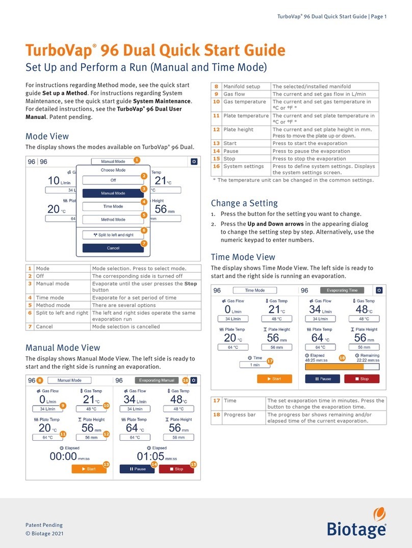
EUTHANEX SMARTBOX EA-34004C User manual

1
Auto CO2Lab Control Unit
Model – EA-34004C
1-877-559-0159 Toll Free Euthanex Corp. / E-Z Systems
1-610-882-3801 Fax P.O. Box 3544
www.euthanex.com Palmer, PA 18043

2
Table of Contents
Disclaimer…………………………………………………………………………….3
Smartbox Lab Control Unit Overview……………………………………………….4
System Set-up..……………………………………………………………………….5
Operating the System…………………………………………………………………8
Changing System Presets……..………………………………………………………9
Flow Rate & Preset Times …………..………………………………………………11

3
THIS MANUAL MUST BE READ BEFORE SETTING UP AND OPERATING
THE SMARTBOX AUTO CO2SYSTEM. The user should be thoroughly familiar with
the contents of this manual prior to using the system with animals. Only technicians that
are properly certified should operate the system.
The user/owner of this equipment shall have the sole responsibility for any damage or
injury resulting from operation that is not in accordance with the authorized instructions.
This includes, but is not limited to, operating the equipment outside of recommended
safety levels, variation from specified operating instructions and not following standard
laboratory safety procedures when working with anesthetic agents and volatile
compressed gases.
The system and its components must only be modified or repaired by Euthanex
authorized service technicians. Improper modification or repair may result in danger to
personnel, harm or death to animal, and/or equipment damage. The user/owner of this
equipment shall have the sole responsibility for any damage or injury resulting from
improper maintenance and repair that is not done by authorized maintenance and repair
personnel.
Parts that have failed, in whole or in part, exhibit excessive wear, are contaminated or are
otherwise at the end of their useful life, should not be used and should be replaced with
parts supplied by Euthanex Corporation. Tampering with the main control unit by
unauthorized personnel automatically voids all warranties and specifications. The
manufacturer assumes no responsibility for any malfunction or failure of the unit if
tampering is suspected.

4
Overview:
The Lab Control Unit utilizes a programmable logic controller (PLC) that delivers a set
volume of CO2into individual animal cages through the Euthanex Lid. The controller
unit operates at a fixed flow rate that is set at your external CO2source. Gas flows from
the external source into the Lab Control Unit. A solenoid valve opens to output gas to the
Euthanex lid. After the euthanasia cycle is completed, the Lab Control Unit
automatically shuts the gas off.
The EA-34004C model has four gas outputs - treating up to four cages independently.
The Lab Control Unit comes with preset gas delivery timings. The EA-34004C features
four toggle switches that offer the operator a choice of output channel or channels to start.
Each channel can have a different time settings. It is highly recommended that only
designated, trained personnel make adjustments to the timings, to ensure safe and
effective settings.
Please refer to the “Flow Rate & Preset Times” section to derive the AVMA
recommended flow rate.

5
System Set-Up:
1. Four mounting brackets are utilized to secure the controller unit to the wall. These are
on the controller when shipped.
2. Using a Phillips head screwdriver loosen the screws and move the mount tabs outward
as pictured below. Tighten the screws once appropriate position is achieved.

6
3. With the mounting brackets moved, position the unit in the appropriate location on the
wall and mark the four holes. Remove unit from wall and drill the holes. Secure the unit
to the wall with appropriate screws. (Wall screws are not included.)
4. Connect the external CO2gas line from the regulator or flow meter, to the gas input of
the Lab Control Unit. Check the Flow Rate Guide to determine the correct LPM settings.
Gas In

7
5. Connect the supplied cage hoses from the outputs of the Lab Control Unit to the input
valve on the Euthanex Lid(s). To properly make the connection, pull back the coupler
and slide it over the male stem. The coupler will snap back into place and secure the
connection.
GAS WILL NOT FLOW INTO LID IF THE COUPLER IS NOT PROPERLY
ATTACHED.
GAS WILL FLOW IF A CYCLE IS STARTED FOR AN UNATTACHED OUTPUT.
6. Place the Euthanex Lid(s) on the cage(s), and the system is ready for operation.

8
Operating the Lab Control Unit :
1. Confirm that the CO2source is open and the regulator/flow-meter is set for the correct
flow rate.
2. Move the toggle on/off switch located on the left side of the unit to the on position
(UP). The green “Ready” light will turn on.
3. The EA-34004C offers four independent channel operation with single timing for each
output.
4. To begin the euthanasia cycle, move the toggle up on the desired chamber.
* The red “Run” light will turn on, indicating that the cycle is operating.
* When the cycle is complete, the red light will shut off and the gas flow will stop.
* The green “Ready” light will turn on, indicating the cycle is complete and the
system is ready to run the next cycle.
Cycle Start
Toggle

9
Changing the System Presets
Preset times were determined based on extensive testing done by Euthanex Corp. and
designed to comply with the latest guidelines of the AVMA Panel on Euthanasia. Refer
to the Flow Rate to determine AVMA compliant flow rates and the timing presets. The
following is the procedure for changing the preset times:
1. Release the two latches to open the controller door.
2. The start-up screen will appear on the PLC.
3. To change the preset cycle times, press “ESC”. The option screen will appear.
4. Press the down button to move the arrow to: “> Set Param”. Press “OK”.

10
5. “Timer 1” will screen appear.
* Press “OK” and the first number will begin to flash.
* Use the up/down keys to increase or decrease the value.
* Use the right/left keys to move the cursor to the number you would like to
change.
* After the proper time is set, press “OK”.
Note: Only the T = 00:00m will be set. The Ta = 00:00 is not a programmable function.
6. The EA-34004C offers four programmable timer settings. Press the up/down keys to
navigate the timer choices. When the desired timer appears, repeat step five to change the
time.
7. After setting the timers, press the “ESC” button twice to return to the opening screen.
The Lab Control Unit is now ready to operate. Close and latch the door.

11
Flow Rate & Preset Times:
Default times were chosen to comply with the latest guidelines of the AVMA Panel
on Euthanasia and through extensive testing performed by Euthanex Corp. Times are
programmable and may be changed by a designated administrator.
Preset Times:
Chamber A = 5 minutes
Dwell = 5:00
Chamber B = 5 minutes
Dwell = 5:00
Chamber C = 5 minutes
Dwell = 5:00
Chamber D = 5 minutes
Dwell = 5:00
How to derive AVMA compliant flow rate from chamber size (for a single chamber):
Height(in) x Width(in) x Length(in)= Liters x 20% = flow rate (for a single chamber)
61
(For multiple chambers – add flow rates together)
The 2013 AVMA Euthanasia Guidelines recommend 10 – 30% fill rate.
Table of contents
Other EUTHANEX Laboratory Equipment manuals
Popular Laboratory Equipment manuals by other brands
IKA
IKA MS 450 Swirler operating instructions
DH Lifelabs
DH Lifelabs AquaSolvo AAE-30 06 Series instruction manual
Bertin Instruments
Bertin Instruments Precellys 24 Touch user manual
MedKlinn
MedKlinn Home Asens+ Series operating manual
TQC Sheen
TQC Sheen GLOSSMETER GL0010 operating instructions
Leica
Leica HistoCore AUTOCUT Instructions for use
Agilent Technologies
Agilent Technologies Cary 8454 installation guide
Hettich
Hettich EBA 200 operating instructions
SciCan
SciCan statim 5000 G4 Operator's manual
Coralife
Coralife TurboTwist Series instructions
HAVER & BOECKER
HAVER & BOECKER HAVER EML 200 Premium operating instructions

Cole Parmer
Cole Parmer ShatterBox SM-300 Operation manual
