EUTHANEX SMARTBOX TT-4000 User manual

AutoCO2System
TabletopSystem
877‐559‐0159TollFreeEuthanexCorp./E‐ZSystemsInc.
610‐559‐0159PhoneP.O.Box3544
610‐821‐3061FaxPalmer,PA18043
www.euthanex.com[email protected]

2
TABLE OF CONTENTS
Disclaimer/SystemOverview____________________ 3
Saftey________________________________________ 4
SystemSetup__________________________________ 5
OperatingtheSystem___________________________10
ProgrammingthePresets________________________14
Troubleshooting_______________________________19
EMC / EMI.
This equipment has been tested and found to
comply with the limits for a Class A Equipment,
pursuant to part 15 of the FCC rules.
IEC 61326-1:2005 / EZ 61326-1:2006
For the customers in Canada:
This Class A Equipment complies with
Canadian ICES-003:2012.
Cet appareil numérique de la classe A est
conforme à la norme NMB-003:2012 du Canada.

3
DISCLAIMER
THIS MANUAL MUST BE READ BEFORE SETTING UP AND OPERATING THE AUTO CO2
SYSTEM. The user should be thoroughly familiar with the contents of this manual prior to using the system with
animals. Only technicians that are properly certified should operate the Auto CO2System.
The user/owner of this equipment shall have the sole responsibility for any damage or injury resulting from
operation that is not in accordance with the authorized instructions. This includes, but is not limited to, operating
the equipment outside of recommended safety levels, variation from specified operating instructions and not
following standard laboratory safety procedures when working with anesthetic agents and volatile compressed
gases.
The system and its components must only be modified or repaired by Euthanex-authorized service technicians.
Improper modification or repair may result in danger to personnel, harm or death to animals and/or equipment
damage. The user/owner of this equipment shall have the sole responsibility for any damage or injury resulting
from improper maintenance and repair that is not done by authorized maintenance and repair personnel.
Parts that have failed, in whole or in part, exhibit excessive wear, are contaminated or are otherwise at the end of
their useful life, should not be used and should be replaced with parts supplied by Euthanex Corporation.
Tampering with the controller unit by unauthorized personnel voids all warranties and specifications. The
manufacturer assumes no responsibility for any malfunction or failure of the unit if tampering is suspected.
TABLETOP SYSTEM OVERVIEW
The SMARTBOX Tabletop Auto CO2System is an advanced automated euthanasia unit that has been developed
specifically for euthanizing small rodents. The system incorporates two key components, the SMARTBOX TT
Controller and the TT Chamber. The system works with preset timings that assure humane and efficient levels of
CO2. The controller has 2 timer settings for operation times for Adult and Neonates. Gas flow rate is set at the
source (fixed flow), while the timings are controlled by the automated controller unit. The controller does not
impact the flow rate, but delivers gas at the rate that is output by the source.
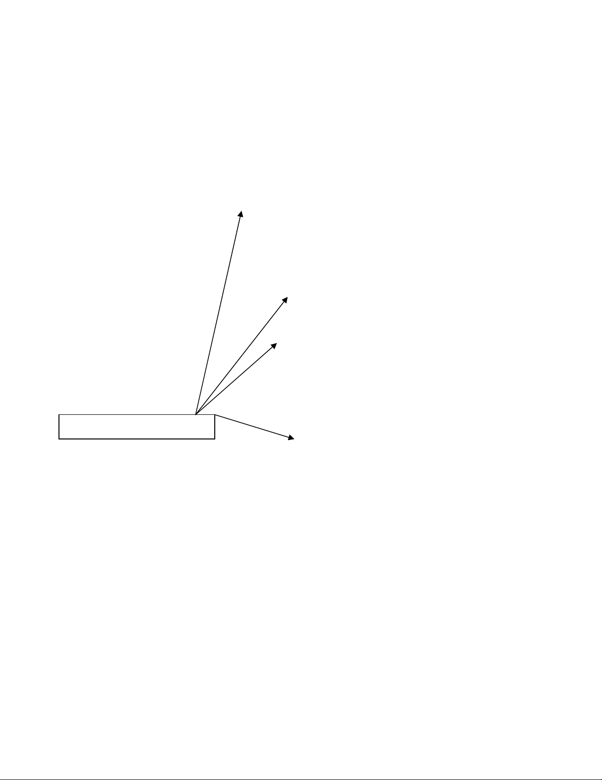
The TT-SB Controller operates in preset automated stages:
1) GasFlowLevelOne:FlowrateissettoconformtotheAVMAguidelinesforhumane
euthanasia.CO2flowsintothetopchamberandanesthetizestheanimalswithminimal
stress.Whiletheanimalsareanesthetized,thegasflowcontinuesandincreasesthe
chamber’sCO2concentrationtoeuthanizinglevel.
2) DwellTime:Gasflowshutsoffandthechamberremainsfullychargedtoassure
euthanasiaofallanimals.
3) ExhaustTime:TheexhaustblowerwillactivateandremoveCo2frominsidethechamber.
(Theexhaustblowerisanoptionalaccessory.)
T
h
s
y
i
n
u
n
pr
m
pe
1.
2.
3.
4.
5.
6.
7.
8.
9.
1
0
1
1
1
2
h
e lightning fla
s
y
mbol within an
n
tended to alert t
h
n
insulated "dan
g
r
oduct's enclosu
r
m
agnitude to con
s
e
rsons.
Read these i
n
Keep these i
n
Heed all wa
r
Follow all i
n
Do not use t
h
Do not clea
n
unit.
Do not bloc
k
Install in ac
c
instructions.
Do not insta
l
as radiators,
unit that pro
d
Do not defe
a
p
olarized or
p
olarized pl
u
wider than t
h
has two bla
d
p
rong. The
w
are provided
p
lug does n
o
electrician f
o
outlet.
0
.Protect the p
on or pinche
d
convenience
where they
e
1
.Unplug this
u
storms or w
h
time.
2
.Refer all ser
v
p
ersonnel. S
e
unit has bee
n
such as pow
e
damaged, li
q
have fallen i
n
unit has bee
n
moisture, do
e
b
een droppe
d
s
h with an arrow
equilateral tria
n
h
e user to the p
r
g
erous voltage"
w
r
e that may be o
f
s
titute a risk of
e
n
structions.
n
structions.
r
nings.
n
structions.
h
is unit near wa
t
n
by s
p
raying liq
u
k
any ventilatio
n
c
ordance with th
e
l
l near any heat
s
heat registers, s
t
d
uce heat.
a
t the safety pur
p
grounding-type
u
g has two blad
e
h
e other. A grou
n
d
es and a third g
r
w
ide blade or th
e
for your safety.
o
t fit into your o
u
o
r replacement
o
ower cord from
d
particularly at
receptacles, an
d
e
xit from the uni
t
u
nit during ligh
t
h
en unused for l
o
v
icing to qualifi
e
e
rvicing is requ
i
n
damaged in an
y
er
-supply cord o
q
uid has been sp
i
n
to the unit, the
n
exposed to rai
n
e
s not operate n
o
d
.
hea
d
n
gle, is
r
esence of
w
ithin the
f
sufficient
e
lectric shock to
t
er.
u
id directly ont
o
n
openings.
e
manufacturer'
s
s
ources such
t
oves, or othe
r
p
ose of the
plug. A
e
s with one
n
ding type plug
r
ounding
e
third prong
If the provide
d
u
tlet, consult an
o
f the obsolete
being walke
d
plugs,
d
the point
t
.
t
ning
o
ng periods of
e
d service
i
red when the
y
way,
r plug is
i
lled or objects
n
o
r
o
rmally, or has
4
o
s
The
e
inten
d
oper
a
the li
t
War
n
Caut
Serv
i
Volta
Press
Tem
p
e
xclamation poi
n
d
ed to alert the
u
a
ting and mainte
n
t
erature accomp
a
n
ing!
To reduce
t
do not exp
o
moisture.
Use line co
Be advised
require the
cord and at
t
shipped wi
t
installation
contact us
f
This equip
m
socket outl
e
should be
e
Do not inst
Do not ope
n
inside.
ion: You are ca
u
modificati
o
manual co
u
this equip
m
i
ce
There are
n
All service
personnel.
ge100‐
2
selec
ure75p
s
p
0to
con
d
n
t within an equ
i
u
ser to the prese
n
n
ance (servicin
g
a
nying the prod
u
t
he risk of fire o
r
o
se this unit to r
a
r
d
supplied wit
h
that different o
p
use of different
t
achment plugs.
t
h the requested
requirements c
h
f
or the correct p
l
m
ent should be
i
e
t and disconne
c
e
asily accessible
.
all in a confine
d
n
the unit - risk
u
tioned that any
o
ns not expressl
y
u
ld void your au
t
m
ent.
n
o use
r
-servicea
b
must be perfor
m
2
40vac50‐60h
z
t)
s
imaxtoinlet
40°C<>10to
8
d
ensation)
i
lateral triangle
i
n
ce of importan
t
g
) instructions i
n
u
ct.
r
electric shock,
a
in o
r
h
the product.
p
erating voltage
s
types of line
The unit was
plug. If the
h
ange please
l
ug.
i
nstalled near th
e
c
tion of the devi
c
.
d
space.
of electric shoc
k
change o
r
y
approved in th
i
t
hority to operat
b
le parts inside.
m
ed by qualifie
d
z
1ampMax(a
u
8
5%RH(no
i
s
t
n
s
e
c
e
k
i
s
e
d
u
to
SYSTEM SETUP
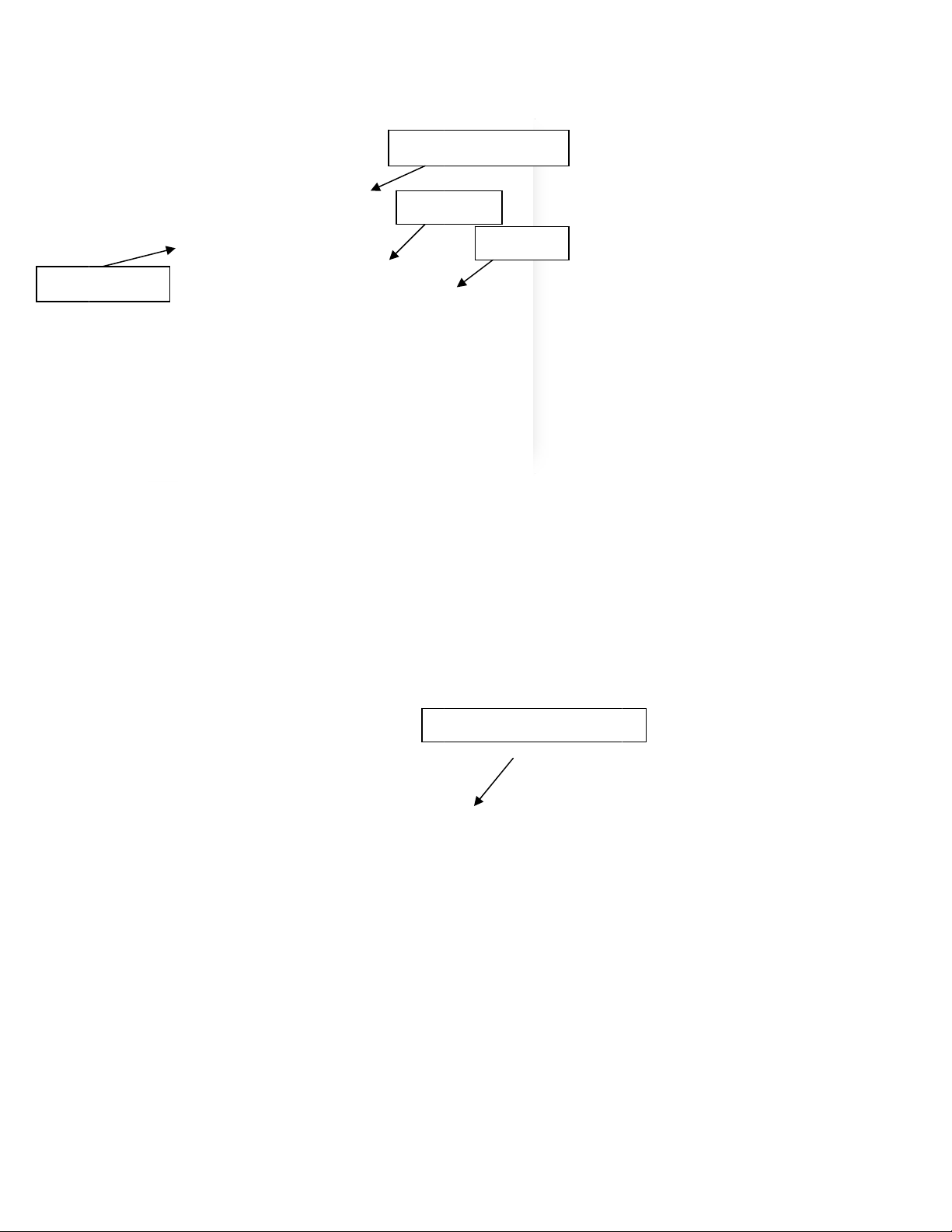
1) TheSMARTBOXTTcontrollerisattachedtotheTabletopchamberutilizingthefourholesonthe
rightsideoftheChamber.
2) Alignthethreadednutinsertsofthecontrolboxwiththefourholesontherightsideofthe
chamber.InserttheM4screwsandusecautiontighteningthemtopreventdamagetothe
chamber.
Screwmountsonchamberside

6
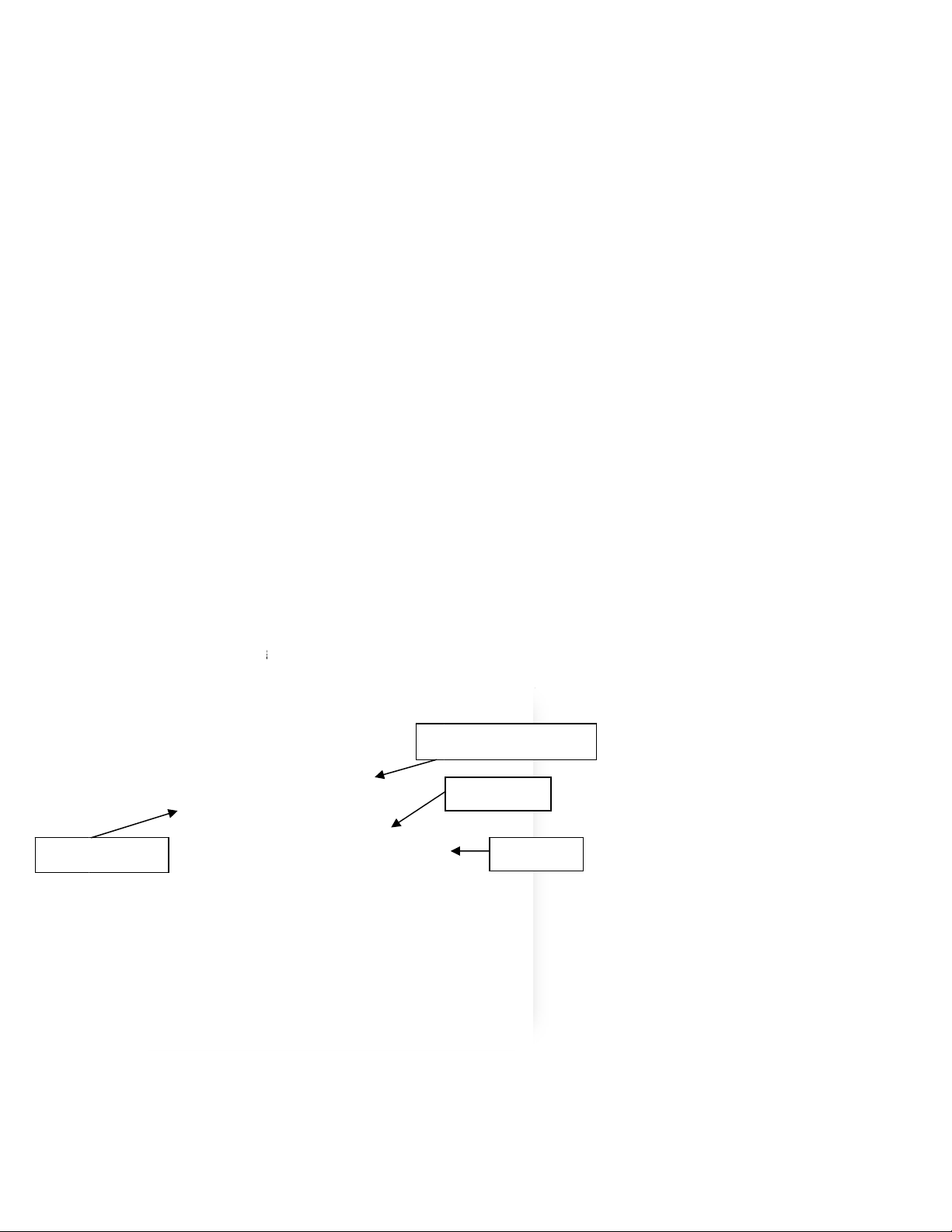
1) Attachthesupplied1/2”checkvalveontotheleftsideofthechamber.Thevalveisthreaded
andwillscrewintothechamberwall.Attachthesupplied1/2”hoseontotherightsideoftop
chamber.Thishoseiscomingoffoftheexhaustblowerunit.
The4”hosefromtheblowerunitcanbedrapedtothefloor,setintoahoodoritcanbeattachedto
houseexhaust.
2) AttachtheCO2supplyfromthecontrolboxtothechamber.Thebraidedhoseisalready
attachedtothechamber,justplacethequickdisconnectfittingtothestemonthebacksideof
theTTController.

5)Attac
tank
t
TheE
regul
a
htheheated
t
hreadsbefo
r
A‐285Electr
i
a
torwilllike
l
regulatorto
r
eattaching
r
i
callyHeated
l
yresultinfr
o
theCO
2
tank
r
egulator.Us
Regulatoris
o
zenCO
2
lin
e
7
.Itisrecom
m
eawrencht
o
requiredto
o
e
s.
m
endedthat
o
tightenthe
o
peratethe
s
Teflontape
b
mountedre
g
s
ystem.Usi
n
b
eusedonth
g
ulator.Not
e
n
ganon‐hea
t
eCO
2
e
:
t
ed
CO
2
T
a
6)Plug
t
turn
o
press
press
contr
o
clock
w
7)Attac
SMA
R
a
nkValve
t
heregulator
o
nandoffhe
urefromthe
urereduces
a
o
lsflowoutp
w
iseorcoun
t
hthetubing
b
R
TBOXTTco
n
intoanACo
u
atasneeded
CO
2
tank.A
f
a
ccordingly.
T
utincubicf
e
t
erclockwise.
b
etweenthe
n
troller.Thei
n
u
tlet.There
g
tomaintain
C
f
ulltanktypi
c
T
heregulato
r
e
etperhour(
CO
2
regulat
o
n
putintothe
Tank
P
Flow
C
O
8
g
ulatoristhe
C
O
2
tempera
t
c
allyrunsat
8
r
flowoutput
CFH).Theo
u
o
routputhos
e
controlbox
u
P
ressureGau
g
Gauge
Valve
B
O
2
Inputinto
rmostaticall
y
t
ure.Thelar
g
8
00lbsPSI.
A
isindicated
o
u
tputiscont
r
e
tothe“CO
2
u
tilizesaqui
c
g
e
B
ar
ControlBox
y
controlledt
o
g
ergaugein
d
A
sthetankis
o
nthesmall
e
r
olledbytur
n
IN”onbott
o
c
kconnectfit
o
automatica
d
icatesthe
used,theta
n
e
rgauge.It
n
ingthevalv
e
o
mofthe
ting.
lly
n
k
e
bar

9
8)PlugblowercontrolcordintotheSMARTBOXTTcontroller.
Plugblowerunitacintomainpowersource.
Blowerunitonlyoperateswhenexhaustcycleisengagedbycontroller.
Ventexhaustclosetoroomreturnvent.
9)PlugACcordfromSMARTBOXTTcontrollerintoACpoweroutlet.
10)Turnonmainpower,readylightwillcomeon.
Setupisnowcomplete.

10
OPERATING THE SYSTEM
1)PresstheOnswitchthatisonthebottomofthecontroller.Thegreen“READY”lightwillturnon.
2)Releasethethreelatchesonthefrontofthechambertoopenthelid.
On
/
OffSwitch

11
3)Thechamberisnowreadytobeloaded.Cageswithwirebarlidscanbestackedintwolayers.
ATT‐8100chambercanaccommodateupto8standardmousecages.ATT‐4000chambercan
accommodateupto6standardmousecages.Numberofcagesaccommodatedwillvarybased
uponactualcagesize.Donotattempttoplacemorecagesthenwillcomfortablyfitintothe
chamber.
NOTE:Cagesshouldbesetaskewtoallowoptimalpenetrationofgastothelowercages.
CO
2
T
a
4)After
fully
s
5)Open
gaug
e
a
nkValve
thechambe
r
s
ecured,asli
g
thegasflow
e
shouldber
e
r
isloaded,cl
o
g
htgasleak
m
fromtheCO
2
e
ading800P
S
o
sethelida
n
m
ayoccur.
2
tankbytur
n
S
Iifthetank
i
Ta
12
n
dsecurethe
n
ingthetank
i
sfull,lessif
i
nkPressure
G
FlowGaug
e
Valv
e
threelatche
valveknobc
o
i
tisnotafull
G
auge
e
e
Bar
stoseal.If
t
o
unterclock
w
tank.
t
helatchesa
r
w
ise.Thelar
g
r
enot
g
ePSI

13
6)Openthegasflowoutoftheregulatorbyturningthe“T”barcounterclockwise.Thisbeginstheflow
ofgastothecontroller.Settheregulatorflowrateat50CFHfortheTT‐8100or33CFHfortheTT‐
4000.
7)Thesystemhastwopresettimersforspeciesselection.Pressupfor“ADULTS”ordownfor
“NEONATES”onthefrontofsidecontrolbox.Thered“RUN”lightindicatestheeuthanasiacycleis
operating.
8)Duringthefirstinitialrun,adjusttheregulatorflowrateto50CFPH.Thisadjustmentwillassurea
humaneprocess.Animalswillfirstbeanesthetizedwithminimalstressandtheneuthanizedwhile
asleep.Exceedingthisflowratemayintroducestresstoanimalsandresultinoperationoutsideof
AVMAguidelines.(Thisregulatoradjustmentistypicallyonlyrequiredthefirsttimeusingthe
systemandwhenafullCO2tankisfirstputonline.)
9)Thesystemwillcyclethroughtwostages:
Stage1Charging:Gasflowsthroughthechamberfor8:30minutes,fullychargingthechamber
withCO2.
Stage2Dwell:GasflowstopsandthechamberremainsfullychargedwithCO2for5minutes.
Stage3Exhaust:Blowerwillactivatefor3.5minutes,chamberwillunlockandreturntoready
state(green).
StartToggle
Adult
Neonates
CHA
N
Recom
m
Corpora
t
Factory
s
The fo
1.Relea
2.Thes
t
3.Toch
4.Press
N
GING
T
m
ended flow
t
ion an
d
are
d
s
ettings for
p
llowing i
s
sethelatch
t
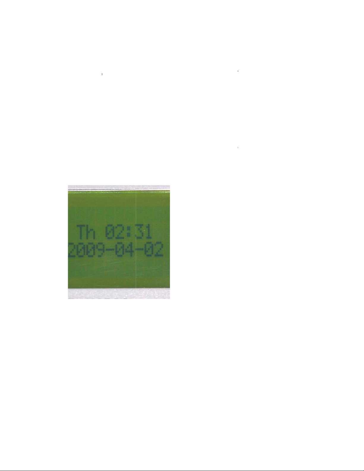
t
art‐upscree
angethepre
s
thedownb
u
T
HE SY
S
rates and pr
e
d
esigned to
p
resets are:
s
the
p
r
o
t
oopenthec
o
nappearson
s
etcycletim
e
u
tton,tomov
S
TEM P
R
e
set times
w
comply wit
h
Adult
C
Dwell:
Dwell:
Exhau
s
o
cedure f
o
o
ntrollerdo
o
thePLC.
e
s,pressESC.
ethearrow
t
14
R
ESET
S
w
ere determi
n
h
the latest
g
C
harging:
Adult
Neonates
s
t
o
r chang
o
r.
Theoption
s
t
o:>“SetPa
S
:
n
ed with ex
t
g
uidelines o
f
8:30 mi
n
5 minut
e
59 minu
t
3:30 mi
n
ing the
p
s
creenwilla
p
ram.”Press
O
t
ensive testi
n
f
the AVM
A
n
utes
e
s
t
es
n
utes
p
reset ti
m
p
pear.
O
K.
n
g done by
E
A
Panel on E
u
m
es:
E
uthanex
u
thanasia.

5.Thec
a.U
b.U
c.A
Note: O
n
6.Repe
a
7.After
syste
m
Repeata
b
ursorwillbli
n
setheup/d
o
setheright/
l
fterthedesi
r
n
ly the T =
0
a
tsteps5an
d
allthetimer
s
m
isnowrea
d
b
ovefortime
n
kforthe“T”
o
wnkeystoi
n
l
eftkeysto
m
r
edtimeisse
t
0
0:00m will
d
6tosetdw
e
s
havebeen
s
d
ytooperat
e
r2.
settings.
n
creaseorde
m
ovethecurs
o
t
,pressOK.
be set. Th
e
e
llandexha
u
s
et,pressthe
e
withthene
w
15
creasethev
a
o
rtothenex
t
e
Ta = 00:0
0
u
sttimes,ifn
ESCbuttont
w
lyprogram
m
a
lue.
t
numberyo
u
0
is not a pr
o
ecessary.
wicetoretu
r
m
edtimes.
C
u
wouldliket
o
grammable
r
ntotheho
m
C
loseandlatc
ochange.
function.
m
escreen.Th
hthedoor.
e

16
FseriesIDECorSiemens:
1.Releasethetwolatchestoopenthecontrollerdoor.
2.TheclockscreenisonthePLC.
3.Tochangethepresetcycletimes,pressESC,thenOK.Theoptionscreenwillappear.
4.Pressthedownbutton,tomovethearrowto:“>Program”.PressOK.
5.Pressthedownbutton,tomovethearrowto:“>SetParameter”.PressOK.
6.Thepasswordscreenappears.Usetheup/dwandRt/Ltarrowtoinputpassword"CLUTCH"thenhit
OK
6.Timerselectscreenappears.Thisscreenismaybedifferentthatthepicturebasedontheprogram
loaded.

17
*Usetheup/downkeystomovetothevaluetochange.
*Press“OK”andthescreenwillchange.Presstherightarrowuntilslargeboxwillbeoverthetimer.
*Press“OK”andtheboxwillbecomesmallandoverthefirstvalueofthetimer.
*Usetheright/leftkeystomovethecursortothenumberyouwouldliketochange.
*Usetheup/downkeystoincreaseordecreasethevalue.
*Usetheright/leftkeystomovethecursortothenumberyouwouldliketochange.
*Afterthepropertimeisset,pressOK.Theboxwillchangebacktolarge.
Note:onlytheT=00:00mwillbeset.TheTa=00:00isnotaprogrammablefunction.
6.Aftersettingthetimers,pressthe“ESC”buttontoreturntothemainscreen.
Usetheupkeytomovetostart,hit"OK"button,useleftarrowtomovetoYes,Hit"OK"button.
TheLabControlUnitisnowreadytooperate.Closeandlatchthedoor.

18
Operational Parameters
TT-8100
Factory settings for presets are: Adult Charging: 8:30 minutes
Dwell:Adult 5minutes
Dwell: Neonates 59 minutes
Exhaust 3:30 minutes
CO2
Set regulator to 50CFH
Flow meter to 25LPM
TT-4000
Factory settings for presets are: Adult Charging: 8:30 minutes
Dwell:Adult 5minutes
Dwell: Neonates 59 minutes
Exhaust 3:30 minutes
CO2
Set regulator to 33CFH
Flow meter to 16LPM
The heated regulator can be left plugged in since it is
thermostatically controlled and will shut off when the heat is
not required.

19
TROUBLESHOOTING
Before any service is done that would require opening the unit it must be disconnected from the
power source. If your location has lockout-tagout protocols please follow them.
System will not turn on:
1) Makesurepowercordisproperlypluggedin.
2) Makesurethepowerswitchonthebackoftheunitisturnedinthe“ON”position.
Gas is not being delivered to the chamber or the flow rate is not
correct:
1)Checkthatyourgassupplyhasnotrunout.
2)CheckthattheCO2tankvalveisfullyopen.
3)CheckthattheconnectionsfromthegassupplyregulatortothecontrollerCO2inputis
properlymated.
4)Checkthatthegrayhoseinsidethecontrollerisconnectedtothechamberinputfitting.
5)Checkthattheregulatorisopenandsetto50CFH.
6)Checkthattheelectricheater,inlinefromthegassupplytotheregulator,isoperating.The
heaterrunsintermittently,switchingonwhenheatisrequired.Ifthegasisnotadequately
heated,itwillnotflowproperly.
Not all animals are being euthanized after the completion of gas
cycle:
1)Checkthatallconnectionsintheentiresystemareproperlyattached.
2)Checkthatyourgassupplyhasnotrunout.
3)Checkthattheregulatorisproperlysetat50CFH.
4)Itmaybenecessarytorevisesettingsfortheparticularspeciesthatyouarehavingdifficulties
with.Tryextendingflowanddwelltimes.Seepage14forinstructionsonchangingpresets.
Note; If the unit does not have the exhaust blower option , the blower time needs to be set at 00:00
If this troubleshooting guide does not resolve your problem, contact Euthanex Tech Support
1‐877‐559‐0159TollFreeEuthanexCorp./E‐ZSystems
610‐559‐0159PhoneP.O.Box3544
610‐821‐3061FaxPalmer,PA18043
www.euthanex.com[email protected]
This manual suits for next models
2
Other EUTHANEX Laboratory Equipment manuals

Popular Laboratory Equipment manuals by other brands


PerkinElmer
PerkinElmer RamanStation 400 Series Getting started guide

Isotech
Isotech Saturn 877 User maintenance manual/handbook

Star Lab
Star Lab ErgoOne user manual

3D Histech
3D Histech TMA Grand Master 3.2 user guide

Bionova
Bionova IC10/20FR manual

Thermo Forma
Thermo Forma 3920 Operating and maintenance manual


