EXP120K1-HT 120KW DC Charger
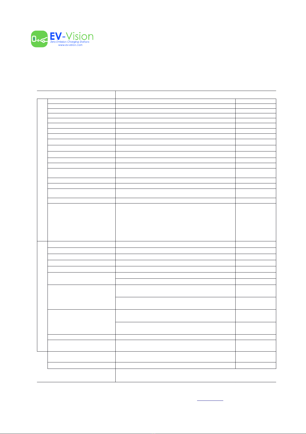
1.4 Performance indicators
Indicators Description Observations
Input number of phases Three-phase and four-line + PE
Input voltage range 400 VAC (+/-10%)
Input frequency 50 Hz/ 60Hz
Max input power 120KW + 20kW
Max input current 233A
System efficiency Total charge ≥94%
Power factor ≥0.99
Harmonic current ≤3% (under certain operating conditions)
Output current accuracy ≤±0.5%
Output current accuracy ≤±0.5%
Ripple coefficient ≤±0.2%
Current sharing ≤±3%
Ground detection ≤30mA
Noise ≤65dB (nominal input / output power, environment temperature
25°C.)
Minimum ingress protection IP 65
Operating mode Vertical operation
Maintenance access Front maintenance access for system and right-side
maintenance access for power modules.
RoHS The system meets R5 requirements in the RoHS directive
Hot plug
The system power modules are quick-connect and do not
need to restart the entire system, however the DC output must
be turned off during the entire power module exchange. After
disconnecting a power module, a break os at least 10 seconds
must be given before reconnecting it. Care should be taken
when replacing the module, inserting it slowly to avoid
mechanical damage to the pins that make the module contact
to the rest of the equipment.
AC output power 22KW
AC output voltage 400 VAC (+/- 10%)
AC output current 32A
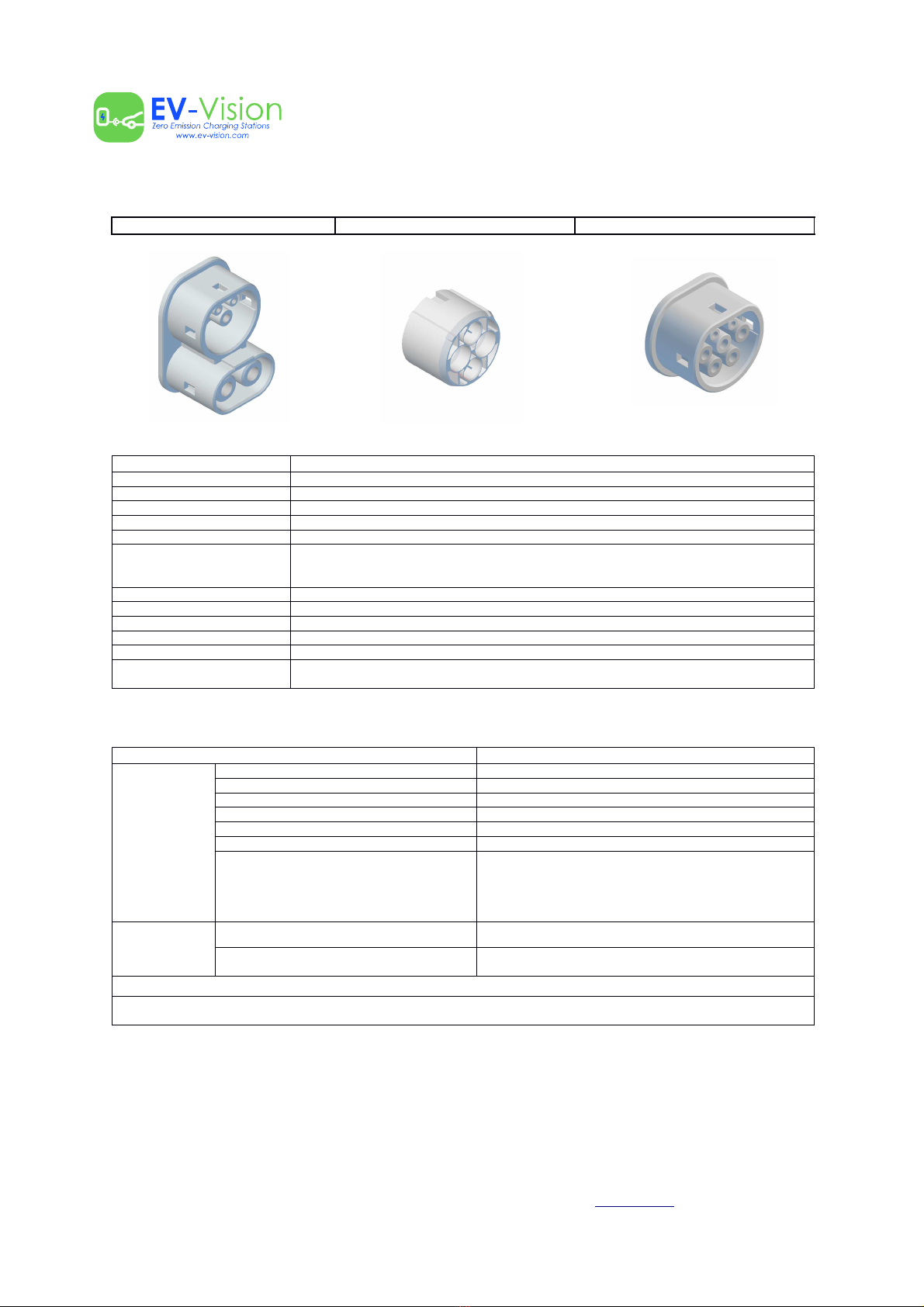
AC connection – 1 piece Mode-3 type 2
DC output power 120KW
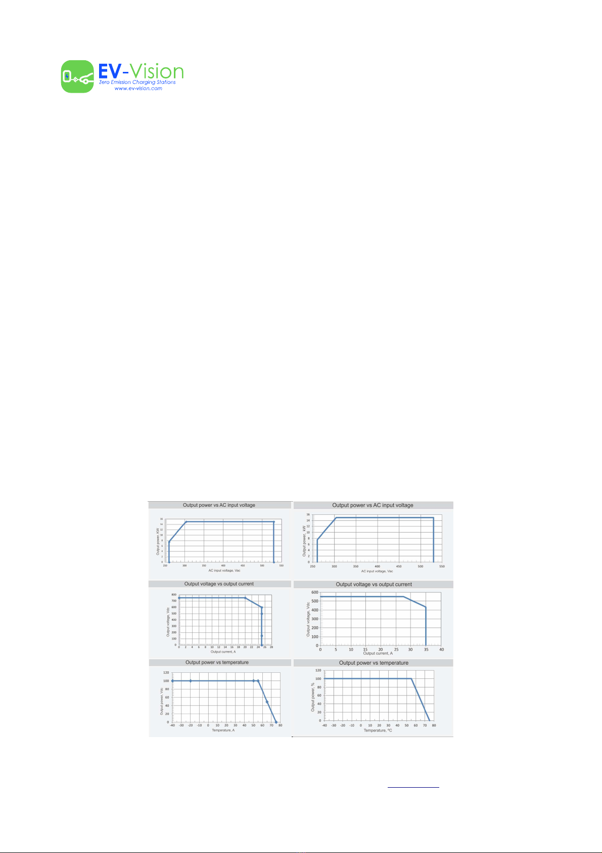
DC output default voltage 600Vdc (when REG75030G power module is use )
500Vdc (when REG50040G power module is use )
DC output voltage range
150Vdc~750Vdc, tolerance ± 1Vdc (when REG75030G power
module is use)
150Vdc~550Vdc, tolerance ± 1Vdc (when REG50040G power
module is use)
DC output current
Maximum load current ≤200A (when REG75030G power
module is use)
Maximum load current ≤200A (when REG50040G power
module is use)
DC connection – 2 units 2 x CCS COMBO 2 or 1 x CCS COMBO 2 + 1 x CHAdeMO
DC distribution voltage drop ≤500mV (a 25°C ambient temperature)
General IEC 61851-1-2017
IEC 62196-1-2012
Security (LV) IEC 60950-1
EMC IEC 61851-21-2
EV Vision – Porto – Portugal – www.ev-vision.com – Support service: (+351) 229 999 230
All rights reserved. This manual may be changed without prior notice. - V 1.0 – 2019/08/10 – Pag. 8 de 25
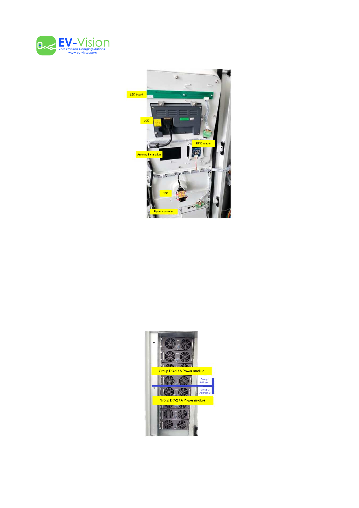
Power distribution unit
Standards System indicators