OTHER WARNINGS
Risk of Fire
Risk of Electrical Shock
Risk of Burns
MEDICAL EQUIPMENT
FCC / IC
This device complies with part 15 of the FCC and Industry Canada
license-exempt RSS standard(s). Operation is subject to the following two
conditions:
(1) this device may not cause harmful interference, and (2) this device must
accept any interference received, including interference that may cause
undesired operation.
NOTE: This equipment has been tested and found to comply with the limits
for a Class B digital device, pursuant to Part 15 of the FCC Rules. These
limits are designed to provide reasonable protection against harmful
interference in a residential installation. This equipment generates, uses
and can radiate radio frequency energy and, if not installed and used in
accordance with the instructions may cause harmful interference to radio
communications. However, there is no guarantee that interference will not
occur in a particular installation. If this equipment does cause harmful
interference to radio or television reception, which can be determined by
turning the equipment off and on, the user is encouraged to try to correct
the interference by one or more of the following measures:
— Reorient or relocate the receiving antenna.
— Increase the separation between the equipment and receiver.
— Connect the equipment into an outlet on a circuit different from that to
which the receiver is connected.
— Consult the dealer or an experienced radio/TV technician for help
Important note: To comply with the FCC RF exposure compliance
requirements, no change to the antenna or the device is permitted. Any
change to the antenna or the device could result in the device exceeding
the RF exposure requirements and void user’s authority to operate the
device.
FCC NOTE: The manufacturer is not responsible for any radio or TV
interference caused by unauthorized modifications to this equipment. Such
modifications could void the user’s authority to operate the equipment.
CAUTION - PLEASE READ!
This device (ZW31) is intended for installation in accordance with the
National Electric Code and local regulations in the United States, or the
Canadian Electrical Code and local regulations in Canada. If you are
unsure or uncomfortable about performing this installation consult a
qualified electrician.
CONTROLLING APPLIANCES
Please exercise EXTREME CAUTION when using Z-Wave devices to
control appliances. Reason being is because the appliance you want to
control may be in a separate room and if unintentional behavior occurs
(such as a device turning on or off - either intentionally via schedules, or
unintentionally via network error) this event may lead to a hazardous
condition. For these reasons, please note the following suggestions:
1) Do not include Z-Wave devices in Groups or Scenes if they control
appliances.
2) Do not use Z-Wave devices to control electric heaters or any other
appliances which may present a hazardous condition due to unattend-
ed, unintentional, or automatic power control
WARNING - SHOCK HAZARD
TURN OFF THE POWER to the circuit for the switch and lighting fixture at
the service panel (circuit breaker) prior to installation.
ALL WIRING CONNECTIONS MUST BE MADE WITH THE POWER OFF to
avoid personal injury and/or damage to the switch.
Please DO NOT use this switch to control Medical or Life Support
equipment. Z-Wave devices should never be used to control the On/Off
status of Medical and/or Life Support equipment.
2020.6.22 V4.0
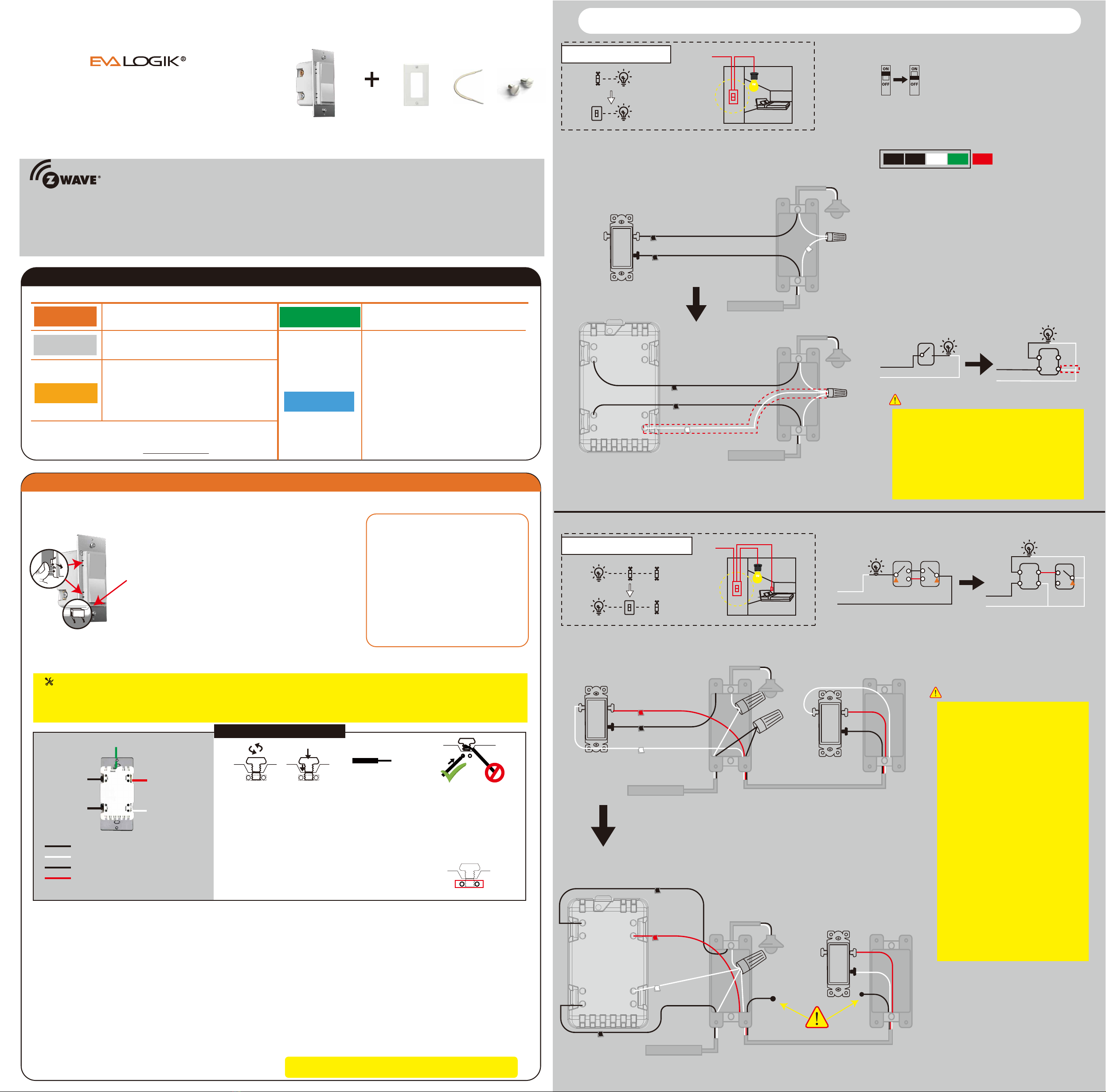
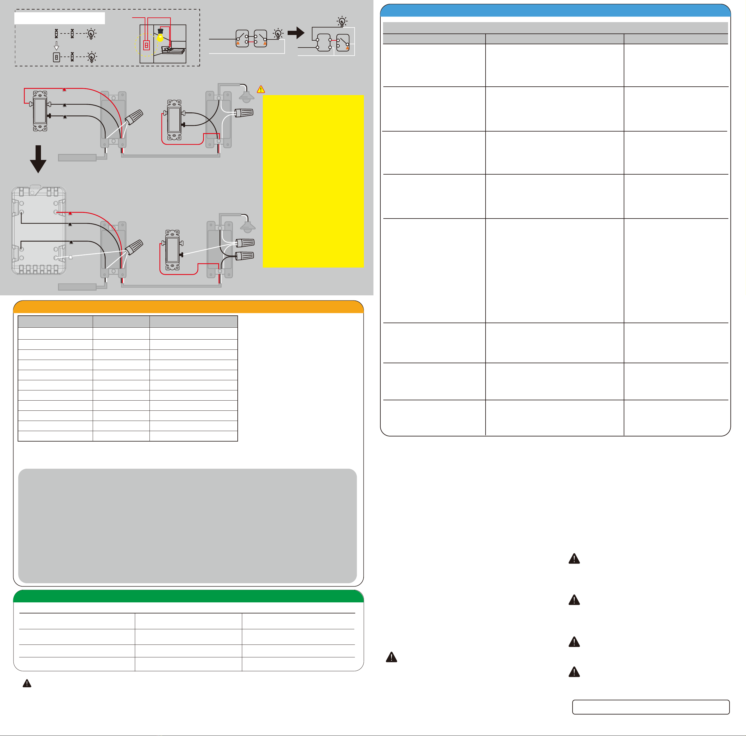
3-Way switch option 2 Power
1) Neutral required. If the switch box do
not have a Neutral, please stop!
Connect the white wire to neutral
terminal (use a white jump wire form
the package or the second hole at the
terminal to connect.)
2) Insert the Line wire to Line terminal
and Load wire to Load terminal.
LOAD and LINE Can’t be swapped,
please make sure to identify them
correctly!
3) Install the smart switch in the switch
box which directly connects to the
power Line and Neutral.
4) Only work with regular 3-way on/off
for 2 locations control. It can only be
connected with regular 3-way on/off
switch, don't use a smart switch or a
dimmer switch! Couldn't work with
an add-on switch!
(Line/Hot and Neutral)
Box 1 (Load)
Don’t replace this
regular 3-way on/off switch
Box 2
IMPORTANT
Neutral
regular 1
regular 2
common
Load
Line
Traveler
common
From source
OUT TO LIGHT
Ground
Load
Neutral
Line
Traveler
Neutral
regular
Load
Line
Traveler
common
From source
OUT TO LIGHT
To exclude and reset the device
Works with Alexa & Google Assistant
To return your switch to factory defaults
Adding your device to a Z-Wave network
Make your controller/hub into the "inclusion"
mode, triple press the Up/Down push button
quickly to include it in the network.
Make your controller/hub into the "exclusion"
mode, triple press the Up/Down push button
quickly to exclude it from the network.
1. Tap-tap and hold the upper paddle for at
least 10 seconds.
Note: This should only be used in the event
your network’s primary controller is missing
or otherwise inoperable.
Scene:
Scene 1: Tap-Down-2
Scene 2: Tap-Up-2 It must be connected to a supported hub in order to interact with the
Amazon Alexa / Google Home services.
1: Press the button 5 times (up/down) quickly, the blue indicator light flashes slowly, enter the setting “Min brightness” mode, and
the load lamp automatically adjusts to the min brightness.
2: Press the up or down button to adjust the brightness of the bulb, select the appropriate brightness to set the min brightness.
3: Quick Press the button 5 times (up/down) to confirm it (the min brightness setting is completed). It will be entered into the “Max
Brightness” setting automatically, the bulb will adjust to the max brightness.
4: Press the up or down button to adjust the brightness of the bulb, and select the appropriate brightness to set the max bright-
ness.
5: Press the button 5 times (up/down) to confirm.
6: Aerconfirmation,the brightness ofthe bulbwillautomaticallybe adjustedfromthesetminbrightnesstothe maxbrightness,
thenfromthemaxbrightnesstotheminbrightness,finallystaysatthesetminbrightness. The blue indicator light stops
flashing.
7: Min / Max brightness level settings are completed.
Remark: If the setting is not confirmed at Step 3/Step 5, the setting mode will be exited aer 10S, and the adjusted value will not
be saved.
Min / Max brightness level setting
Our Products warrants this product to be free from manufacturing defects for a period of one year from the original date of consumer purchase.
This warranty is limited to the repair or replacement of this product only and does not extend to consequential or incidental damage to other
products that may be used with this product. This warranty is in lieu of all other warranties, expressed or implied. Some states do not allow
limitations on how long an implied warranty lasts or permit the exclusion or limitation of incidental or consequential damage, so the above
limitations may not apply to you. This warranty gives you specific rights, and you may also have other rights which vary from state to state.
WARRANTY
If you have any questions, please contact us at
LED Status(Blue) Switch
ON ( Default ) power off ( Default )
power on ( Default )
configuration succeed
inclusion /exclusion
OFF ( Default )
/
/
flash two times
flash two times
flash two times
flash two times
flash quickly
flash quickly
flash slowly
Operation
factory default
change LED status
parameter change
press down
press up
tap-tap and hold 10 seconds
press 6x quickly
press 3x quickly (see below)
press 5x quickly
press 2x quickly
press 7x quickly
press 8x quickly
change locally button function
restores state aer power failure
hold dimmer up or dimmer down
send scene 1 / scene 2
Min / Max brightness level setting
Part 3. Manual Control
Part 5.Parameter Settings
Possible Problem Possible Cause Solution
1. The connected LED is flashed/too bright when
set it to the Minimum brightness level.
2. Couldn't pair with hub/your hub cannot
recognize the device.
3. The device couldn't trun lights on/off manually.
4. The smart switch is working and the 3-way
switch does not.
LED brightness minimum setting is incorrect.
The device needs to be resetted before pairing.
Wiring errore
Please set the minimum brightness level
according to the manual.
Please reset the device according to the manual.
Please check the wiring diagram on the manual.
3-way Wiring error Please check the wiring diagram on the manual.
Part 4. Troubleshooting
Generic Device Class:
0x11- GENERIC_TYPE SWITCH_MULTILEVEL
Specific Device Class:
0x01-SPECIFIC_TYPE POWER_SWITCH_MULTILEVEL
Command Classes:
0x5E - COMMAND_CLASS_ZWAVEPLUS_INFO
0x26 - COMMAND_CLASS_SWITCH_MULTILEVEL
0x85 - COMMAND_CLASS_ASSOCIATION
0x8E - COMMAND_CLASS_MULTI_CHANNEL_ASSOCIATION
0x59 - COMMAND_CLASS_ASSOCIATION_GRP_INFO
0x55 - COMMAND_CLASS_TRANSPORT_SERVICE
0x86 - COMMAND_CLASS_VERSION
0x72 - COMMAND_CLASS_MANUFACTURER_SPECIFIC
0x5A - COMMAND_CLASS_DEVICE_RESET_LOCALLY
0x73 - COMMAND_CLASS_POWERLEVEL
0x70 - COMMAND_CLASS_CONFIGURATION
0x5B- COMMAND_CLASS_CENTRAL_SCENE
0x9F - COMMAND_CLASS_SECURITY_2
0x6C - COMMAND_CLASS_SUPERVISION
0x7A - COMMAND_CLASS_FIRMWARE_UPDATE_MD
Parameter Available settings Operation
The indicator will flashes 2 times aer each parameter set successfully.
Parameter 1:
Button Function Setting
This parameter can access you to set
the up button to turn the light on/off.
Please note: the switching of each value
is in order, a quick press on button 7
times will switch once. eg: Switching
from value 0 to value 2 needs 2 switching.
Size=1
Value=0 (Default)The up button turn the light on and
down button turn lights off.
Value=1 -----------The up button turn the light off and down
button turn lights on.
Value=2 -----------The up/down button both can changes
the state of the light.
Quick press the switch button 7 times
Parameter 2:
LED Indicator Status Setting
This parameter can access you to
choose the led indicator to be on
when the switch(light) is on/off, or
LED indicator remains on/off all times.
Size=1
Value=0 (default) LED is On when the switch(light) Off
and LED is Off when the switch (light) On.
Value=1 -----------LED is On when switch(light) On and
LED is Off when the switch(light) Off.
Value=2 -----------LED is always Off.
Value=3 -----------LED is always On.
Please note: the switching of each value
is in order, a quick press on button 6
times will switch once. eg: Switching
from value 0 to value 3 needs 3 switching.
Quick press the switch button 6 times
Parameter 8:
Restores State aer Power Failure
This parameter can access you to set the
switch to be on/off aer power failure.
Size=1
Value=1-----------The switch is off regardless of the state
prior to power failure.
Value=2(default) memory state before power failure
This switch will be return to state prior to the power failure
aer power is restored.
Please note: the switching of each value
is in order, a quick press on button 8
times will switch once. eg: Switching
from value 0 to value 2 needs 2 switching.
Quick press the switch button 8 times
Parameter 4:
Auto Turn-Off Timer.
This parameter can access you to set a
timer to make the switch turn off automati-
cally aer the switch turned on.The
numberentered as value corresponds to
number of minutes.
Size=4
Values: 0 – 65535 (minutes);
Value=0 (minutes) – default setting Set up on the hub
Parameter 6:
Auto Turn-On Timer.
This parameter can access you to set a
timer to make the switch turn on automati-
cally aer the switch turned off.The
numberentered as value corresponds to
number of minutes.
Size=4
Values: 0 – 65535 (minutes);
Value=0 (minutes) – default setting
Set up on the hub
direct control of other devices
within the Z-Wave system network.
Association Group:
Linking devices: Group 1 supports 1 node ID,
Group 2 Supports maximum of 5 node ID’s
Association group_1:Z-Wave Plus Lifeline
Association Group 2:Send Basic Set ON / Off
Set up on the hub
Parameter=7
Size=1
Default = 1
Value=00 – none
Value=01 - local
Value=02 - 3way
Value=03 - 3way & local
Value=04 - z-wave hub
Value= Value=05 - z-wave hub & local
Value=06 - z-wave hub & 3-way
Value=07 - z-wave hub & local & 3way
Value=08 - timer
Value=09 - timer & local
Value=10 - timer & 3-way
Value=11 - timer & 3-way & local
Value=12 - timer & z-wave hub
Value=13 - timer & z-wave hub & local
Value=14 - timer & z-wave hub & 3-way
Set up on the hub
Association Setting
Size=1,
Value=0 disable
Value=1
/
Value=99
Default = 10
Parameter 11:
Multilevel minimum value can be set
Quick press the switch button 5 times
This parameter can access you to set
Min / Max brightness level setting
Neutral
Line
Smart
Switch
Neutral
Line
common common
common