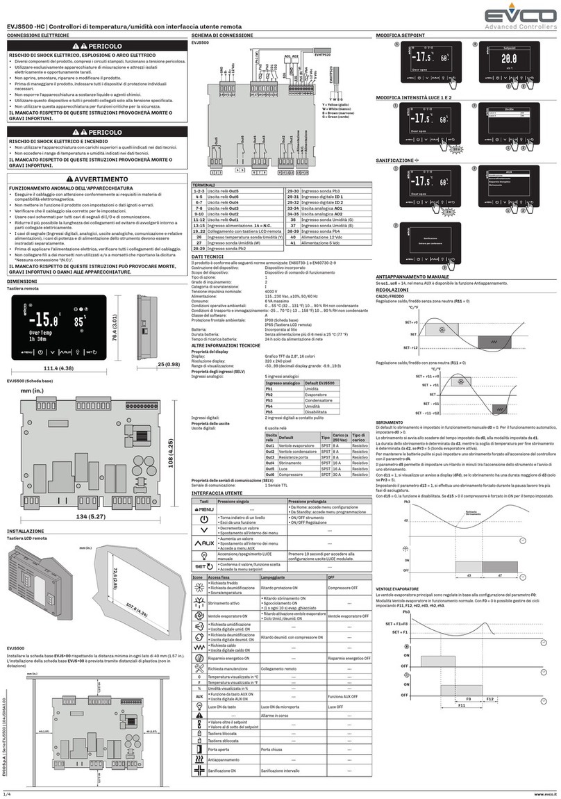
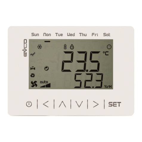
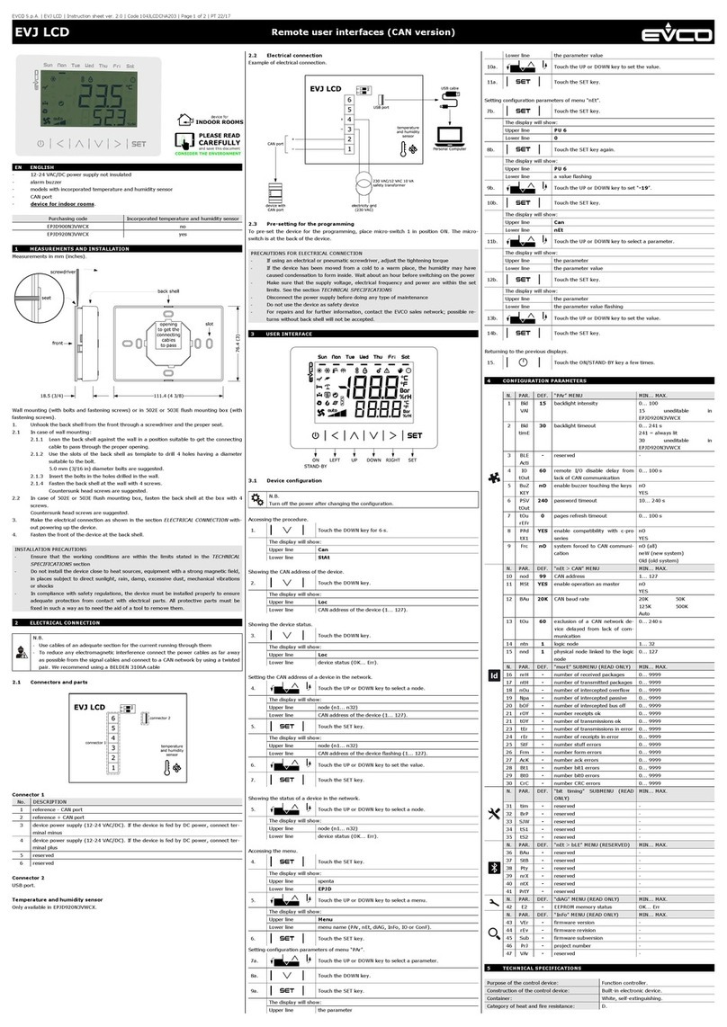
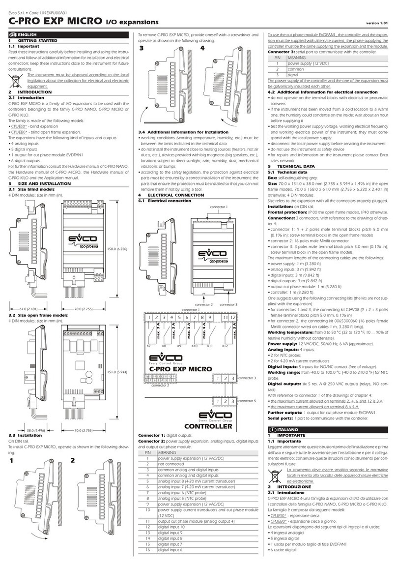
Evco EVJS 500 Split User guide

EVJS 500 Split
Temperature/humidity controllers for refrigerated display
units with remote user interface
WARNING
Make sure you read and fully
understand the manual before
using this device.
Non-observance of these
instructions may result in death
or serious injury.
114JS50E4.00 - 04/2022
Installer manual

114JS50E4.00 ·EVJS 500 Split
CONTENTS
04/2022
| 2 |
IMPORTANT INFORMATION.............................................................................................................. 5
IMPORTANT SAFETY INFORMATION................................................................................................ 6
SAFETY INFORMATION RELATING TO THE PRODUCT..................................................................... 7
1. INTRODUCTION............................................................................................................................... 8
1.1 Description ............................................................................................................................................. 8
1.2 Features .................................................................................................................................................. 8
1.3 Accessories ............................................................................................................................................ 8
2. TECHNICAL DATA.......................................................................................................................... 10
2.1 Technical specications......................................................................................................................10
2.1.1 EVJS 500 Split ............................................................................................................................................10
2.2 I/O specications ................................................................................................................................11
2.2.1 Base board .................................................................................................................................................11
2.3 Remote user interface features .........................................................................................................11
3. MECHANICAL ASSEMBLY............................................................................................................ 12
3.1 Before you start ................................................................................................................................... 12
3.2 Information concerning installation and the surrounding environment .......................................12
3.3 Dimensions............................................................................................................................................13
3.3.1 Base board .................................................................................................................................................13
3.3.2 User interface............................................................................................................................................13
3.4 Installation............................................................................................................................................14
3.4.1 Base board .................................................................................................................................................14
3.4.2 User interface............................................................................................................................................14
3.4.3 Minimum installation distances for the base board ..............................................................................14
4. ELECTRICAL CONNECTIONS........................................................................................................ 15
4.1 Wiring best practices ..........................................................................................................................15
4.1.1 Wiring guidelines.......................................................................................................................................15
4.1.2 Guidelines for screw terminals ...............................................................................................................15
4.1.3 Permitted cable lengths............................................................................................................................16
4.2 Wiring diagram.....................................................................................................................................16
4.2.1 Base board .................................................................................................................................................16
4.2.2 User interface............................................................................................................................................17
5. USER INTERFACE .......................................................................................................................... 18
5.1 Interface ...............................................................................................................................................18
5.2 Touch keys ............................................................................................................................................ 18
5.3 Icons......................................................................................................................................................18
5.4 Using the controller .............................................................................................................................19
5.4.1 Controller ON/OFF ....................................................................................................................................19
5.4.2 Functions that can be activated via key..................................................................................................19
5.4.3 Changing the setpoint ...............................................................................................................................20

114JS50E4.00 ·EVJS 500 Split
CONTENTS
04/2022
| 3 |
5.4.4 Changing the intensity of light 1 and 2 ....................................................................................................20
5.4.5 Setting the clock ........................................................................................................................................21
5.4.6 Accessing the parameters .......................................................................................................................22
5.4.7 Programming menu...................................................................................................................................23
6. DEFROSTING.................................................................................................................................. 24
6.1 Introduction .........................................................................................................................................24
6.1.1 Operating conditions.................................................................................................................................24
6.1.2 Dripping interval........................................................................................................................................24
6.1.3 Defrost types .............................................................................................................................................25
6.2 Modular defrost: RTC ..........................................................................................................................25
6.3 Standard defrost..................................................................................................................................25
6.3.1 Electric heater defrost .............................................................................................................................25
6.3.2 Cycle inversion (hot gas) defrost.............................................................................................................27
6.3.3 Defrost on compressor stoppage............................................................................................................29
7. REGULATORS ................................................................................................................................. 30
7.1 Hot/cold temperature ......................................................................................................................... 30
7.1.1 Operation ...................................................................................................................................................30
7.2 Hot/Cold temperature with neutral zone ..........................................................................................30
7.2.1 Operation ...................................................................................................................................................30
7.3 Temperature and dehumidication with compressor .....................................................................31
7.3.1 Operation ...................................................................................................................................................31
7.3.2 Temperature priority over dehumidication .........................................................................................31
7.4 Humidity ................................................................................................................................................31
7.4.1 Operation ...................................................................................................................................................31
7.5 Humidity with neutral zone..................................................................................................................32
7.5.1 Operation ...................................................................................................................................................32
7.6 Compressor ..........................................................................................................................................32
7.6.1 Operating diagrams ..................................................................................................................................33
7.7 Dual Compressor .................................................................................................................................34
7.7.1 Operating diagram ....................................................................................................................................34
7.8 Evaporator fans....................................................................................................................................35
7.8.1 Operation ...................................................................................................................................................35
7.8.2 Operating modes .......................................................................................................................................35
7.8.3 Operation during a defrost.......................................................................................................................35
7.8.4 Evaporator fan operation during dripping .............................................................................................35
7.9 Condenser fans ....................................................................................................................................36
7.9.1 Operation ...................................................................................................................................................36
7.10 Energy Saving.....................................................................................................................................36
7.10.1 Operation .................................................................................................................................................36

114JS50E4.00 ·EVJS 500 Split
CONTENTS
04/2022
| 4 |
8. FUNCTIONS.................................................................................................................................... 37
8.1 Sanitising...............................................................................................................................................37
8.2 Analogue outputs ................................................................................................................................. 37
8.2.1 Humidity control ........................................................................................................................................37
8.2.2 Dimmed light ..............................................................................................................................................37
8.2.3 Modulating condensation.........................................................................................................................37
8.2.4 Humidication............................................................................................................................................38
8.3 Copying Parameters ...........................................................................................................................38
8.3.1 Introduction...............................................................................................................................................38
8.3.2 Uploading parameters from the controller to EVJKEY..........................................................................38
8.3.3 Downloading the EVJKEY parameters to the controller .......................................................................38
9. REMOTE COMMUNICATION ........................................................................................................ 39
9.1 EPoCA communication via TTL serial .................................................................................................39
9.2 EPoCA and third-party BMS communication.....................................................................................41
9.3 EPoCA communication via RS-485 serial...........................................................................................42
10. PARAMETERS.............................................................................................................................. 43
10.1 Table of conguration parameters ..................................................................................................43
11. DIAGNOSTICS ............................................................................................................................. 49
11.1 Table of alarms...................................................................................................................................49

114JS50E4.00 ·EVJS 500 Split 04/2022
| 5 |
IMPORTANT INFORMATION
Liability and residual risks
EVCO assumes no liability for any damage caused by the following (by way of example; this is not an exhaustive list):
• Installation/useforpurposesotherthanthosespeciedand,inparticular,notadheringtothesafetyprovisionssetout
by current regulations in the country in which the product is installed and/or contained in this manual;
• Useinappliancesthatdonotguaranteesufcientprotectionagainstelectricshocks,wateranddustwithinthe
installation conditions created;
• Useinappliancesthatallowaccesstohazardouspartswithouttheuseofakeyedortooledlockingmechanismwhen
accessing the instrument;
• Tampering and/or modifying the product;
• Installation/use in appliances which do not comply with current regulations in the country in which the product is
installed.
The customer/manufacturer is responsible for ensuring their machine complies with these regulations.
EVCO’s responsibility is limited to the correct and professional use of the product in accordance with regulations and the
instructions contained in this manual and other product support documents.
TocomplywithEMCstandards,observealltheelectricalconnectioninstructions.Asitdependsonthewiringconfigurationas
wellastheloadandtheinstallationtype,compliancemustbeverifiedforthefinalmachineasspecifiedbytherelevantproduct
standard.
Disclaimer
This document is the exclusive property of EVCO. It contains a general description and/or a description of the technical
specifications for the services offered by the products listed herein. This document should not be used to determine the
suitability or reliability of these products in relation to specific user applications. Each user or integration specialist should
conducttheirowncompleteandappropriateriskanalysis,inadditiontocarryingoutaproductevaluationandtestinrelation
to its specific application or use. Users can send us comments and suggestions on how to improve or correct this publication.
Neither EVCO nor any of its associates or subsidiaries shall be held responsible or liable for improper use of the information
contained herein.
EVCOhasapolicyofcontinuousdevelopment;therefore,EVCOreservestherighttomakechangesandimprovementstoany
product described in this document without prior notice.
The images in this document and other documentation supplied with the product are provided for illustrative purposes only and
may differ from the product itself.
The technical data in this manual is subject to change without prior notice.
Terms and Conditions of use
Permitted use
Thedevicemustbeinstalledandusedinaccordancewiththeinstructionsprovidedand,inparticular,hazardousliveparts
must not be accessible under normal conditions.
The device must be suitably protected from water and dust with regard to its application and must also only be accessible with
the aid of a tool (with the exception of the front panel).
Only qualified personnel may install the product or perform technical support procedures on it.
The customer must only use the product as described in the documentation relating to that product.
Prohibited use
Anyuseotherthanthosedescribedinthe"Permitted use"sectionandintheproductsupportdocumentationisprohibited.
Disposal
The device must be disposed of in accordance with local regulations regarding the collection of electrical and
electronic appliances.
Consider the environment
Thecompanyworkstowardsprotectingtheenvironment,whiletakingaccountofcustomerrequirements,
technological innovations in terms of materials and the expectations of the community to which we belong. EVCO
placesgreatimportanceonrespectingtheenvironment,encouragingallassociatestobecomeinvolvedwithcompany
valuesandguaranteeingsafe,healthyandfunctionalworkingconditionsandworkplaces.
Please consider the environment before printing this document.

114JS50E4.00 ·EVJS 500 Split 04/2022
| 6 |
IMPORTANT SAFETY INFORMATION
Please read this document carefully before installation; study all the warnings before using the device. Only use the device in
accordance with the methods described in this document. The following safety messages may be repeated several times in
thedocument,toprovideinformationregardingpotentialhazardsortoattractattentiontoinformationwhichmaybeusefulin
explaining or clarifying a procedure.
Thissymbolisusedtoindicateariskofelectricshock.
Itisasafetyindicationandassuch,shouldbeobservedtoavoidpotentialaccidentsorfatalities.
Thissymbolisusedtoindicateariskofseriouspersonalinjury.
Itisasafetyindicationandassuch,shouldbeobservedtoavoidpotentialaccidentsorfatalities.
DANGER
DANGER indicatesasituationofimminentdangerwhich,ifnotavoided,will lead to death or serious injury.
WARNING
WARNING indicatesasituationofimminentdangerwhich,ifnotavoided,may lead to death or serious injury.
CAUTION
CAUTION indicatesapotentiallyhazardoussituationwhich,ifnotavoided,could cause minor or moderate injury.
NOTICE
NOTICE indicates a situation not related to physical injuries but which
,ifnotavoided,
could damage the equipment.
NOTE:themaintenance,repair,installationanduseofelectricalequipmentmustonlybeentrustedtoqualifiedpersonnel.
QUALIFIED PERSONNEL
Only suitably trained and experienced personnel capable of understanding the content of this manual and all documentation
regardingtheproductareauthorisedtoworkonandwiththisequipment.Furthermore,thepersonnelmusthavecompleted
coursesinsafetyandmustbeabletorecogniseandpreventtheimplieddangers.Thepersonnelmusthavesuitabletraining,
knowledgeandexperienceatatechnicallevel,andbecapableofanticipatinganddetectingpotentialriskscausedbyusing
theproduct,aswellaschangingthesettingsandmodifyingthemechanical,electricandelectronicequipmentfortheentire
systeminwhichtheproductisused.Allpersonnelworkingonandwiththeproductmustbeentirelyfamiliarwiththerelevant
standardsanddirectives,aswellassafetyregulations.

114JS50E4.00 ·EVJS 500 Split 04/2022
| 7 |
SAFETY INFORMATION RELATING TO THE PRODUCT
Beforecarryingoutanyworkontheequipment,readtheseinstructionscarefully,makingsureyouunderstandeverything.
DANGER
RISK OF ELECTRIC SHOCK, EXPLOSION OR ELECTRIC ARC
• Only use electrically insulated measuring devices and equipment.
• Do not install the equipment while the power supply is connected.
• Cutoffthepowersupplytoallequipment,includinganyconnecteddevices,beforeinstalling/uninstallingthedevice.
• AlwaysuseaproperlycalibratedVoltmetertomakesurethesystemispoweredoff.
• Do not touch the unshielded components or the terminals while they are live.
• Donotopen,disassemble,repairormodifytheproduct.
• Do not expose the equipment to liquids or chemicals.
• Before applying voltage to the equipment:
• Makesureallprotectiveelements,suchascovers,hatchesandgrilles,arefittedand/orclosed.
• Checkallwiringconnections.
DANGER
RISK OF ELECTRIC SHOCK AND FIRE
• Do not use the device with loads greater than those indicated in the technical data section.
• Do not exceed the temperature and humidity ranges indicated in the technical data section.
• Usetherequiredsafetyinterlocks(fusesand/ormagnetothermalswitches)ofasuitablesize.
DANGER
RISK OF ELECTRIC SHOCK OR MALFUNCTIONING OF THE EQUIPMENT
Do not use damaged products or accessories.
WARNING
MALFUNCTIONING OF THE EQUIPMENT
• Perform the wiringcarefully,incompliancewithelectromagneticcompatibilityrequirements.
• Makesurethewiringiscorrectforitsapplication.
• Use shielded cables for all I/O signal and communication cables.
• Minimisethelengthoftheconnectionsasmuchaspossible,toavoidwindingthecablesaroundelectricallyconnectedparts.
• Thesignal(digitalandanalogueinputs,communicationandcorrespondingpowersupplies)andpowercablesforthedevice
must be routed separately.
• Beforeapplyingthepowersupply,checkallthewiringconnections.
• Usethenecessarysafetyinterlockswherevertheriskofinjurytopersonneland/orequipmentdamageexists.
• Installandusethisdeviceinacabinetofasuitableclassfortheintendedenvironment,protectedbyakeyedlocking
mechanism or other suitable instruments.
• Intermsofconnectionandthefusesusedinthecircuitsforthepowersupplyandoutputlines,observelocalandnational
regulatory requirements relating to the nominal current and voltage for the equipment in use.
• Do not use this equipment for machine functions that are critical to safety.
• Donotdisassemble,repairormodifytheequipment.
• Do not connect wires to unused terminalsand/orterminalsmarkedwiththetext“Noconnection”(“N.C.”).

114JS50E4.00 ·EVJS 500 Split 04/2022
| 8 |
1.1 DESCRIPTION
EVJS 500 Split controllersrepresentacompletesolutionbyEVCO,suitableforthemanagementof:
• Wine/patisserie cabinets;
• Refrigerated cabinets;
• Refrigerated cold rooms.
1.2 FEATURES
The main features of EVJS 500 Split controllers are:
• 5analogueinputs,ofwhich:
• 4 are analogue inputs for temperature;
• 1 is an analogue input for humidity;
• 2volt-freedigitalinputsthatcanbeconguredviaparameter;
• 2 analogue outputs;
• 6 sealed relay outputs;
• 1 TTL serial port (on the user interface);
• 1 RS-485 serial port (on the user interface);
• EPoCA-compatible;
• Compatible with BMS interfacing via Modbus protocol.
NOTE:
forfurtherinformationregardinginputandoutputspecifications,pleaserefertoparagraph"2.1 Technical
specifications" on page 10.
1.3 ACCESSORIES
The accessories available for EVJS 500 Split controllers are:
Type P/n Description
EVHTP520 Humidity and temperature transducers
EVTP NTC/PTC temperature probes
EVIF25TBX BLEmoduleforconnectiontoEVconnectAPP
EVIF25TWX Wi-Fimodule
EVIF24TSX Module for TTL/RS-485 serial interface
1. INTRODUCTION

114JS50E4.00 ·EVJS 500 Split 04/2022
| 9 |
Type P/n Description
EVIF23TSX ModuleforTTL/RS-485serialinterfacewithbuilt-inclock
EVJKEY Programming flash drive for EVJS models

114JS50E4.00 ·EVJS 500 Split 04/2022
| 10 |
2. TECHNICAL DATA
AllthesystemcomponentsofEVJS 500 Split controllers satisfy European Community (EC) requirements for open systems. They
must be installed in casing or another location designated on the basis of specific environmental conditions and in order to
minimisetheriskofinvoluntarycontactwithhazardousvoltage.UsemetalcasingtoimproveEVJS 500 Split system immunity to
electromagnetic fields. This equipment satisfies the EC requirements as indicated in the tables below.
WARNING
MALFUNCTIONING OF THE EQUIPMENT
Do not exceed any of the nominal values specified in this section.
2.1 TECHNICAL SPECIFICATIONS
2.1.1 EVJS 500 Split
Type Description
The product complies with the following harmonised
standards:
EN60730-1 and EN60730-2-9
Device construction: Incorporated electronic device
Device purpose: Operating control device
Type of action: 1
Pollution category: 2
Overvoltage category: III
Nominal pulse voltage: Base board: 4000 V
User interface: 330 V
Power supply: Base board:115...230Vac,±10%,50/60Hz
User interface: 12 Vdc from base board
Consumption: 6VAmaximum
Ambientoperatingconditions:
0...55°C(32...131°F)10…90%RHnon-condensing
Transportation and storage conditions:
-25...70°C(-13...158°F)10…90%RHnon-condensing
Software class: A
Ambientfrontprotection: Base board: IP00
User interface: IP65

114JS50E4.00 ·EVJS 500 Split 04/2022
| 11 |
2.2 I/O SPECIFICATIONS
2.2.1 Base board
Type Description
Digital inputs: 2 voltage-free digital inputs
Analogueinputsfortemperature: 5 analogue inputs for NTC or PTC or humidity probe
Analogueoutputs: 2 configurable analogue outputs
Digital output (SELV): 6 digital outputs
Analogue input specications
Default
NTC
10 kΩ at 25 °C
BETA 3435
PTC
KTY 81-121
990 Ω at 25 °C
RH
EVHTP500
RH
EVHTP520
Pb1 Cold room
probe • •
Temperature Temperature
Pb2 Evaporator
probe • • --- ---
Pb3 Disabled • • --- ---
Pb4 Disabled • • --- ---
Pb5 Humidity probe
EVHTP520 --- --- • •
Range --- -50...120 °C
(-58...248°F)
-50...150 °C
(-58...302°F) 5...95%RH
Solution --- 0.1°C(1°F) 1%
Input
impedance --- 10kΩ 990Ω ---
Digital output specications
Relay output Default Description Load (at 250 Vac) Load type
Out1 Evaporator fans SPST 8A Resistive
Out2 Condenser fans SPST 8A Resistive
Out3 Door heaters SPST 8A Resistive
Out4 Defrosting SPST 16A Resistive
Out5 Light SPST 16A Resistive
Out6 Compressor SPDT 30A Resistive
2.3 REMOTE USER INTERFACE FEATURES
Type Description
Display: 2.8”graphicTFT,16colours
Display resolution: 320 x 240 pixel
Display range: -50...99 (large display decimals: -9.9...19.9)
Serial port: 1 TTL serial port

114JS50E4.00 ·EVJS 500 Split 04/2022
| 12 |
3. MECHANICAL ASSEMBLY
3.1 BEFORE YOU START
Read this manual carefully before installing the system.
Inparticular,thesafetyinstructions,electricalrequirementsandcurrentregulationsforthemachineortheprocessinwhich
this device is involved must be observed. The use and application of the information contained herein requires experience in
thedesignandprogrammingofautomatedcontrolsystems.Onlytheuser,integratorormanufacturerofthemachinecanbe
familiarwithalltheconditionsandfactorswhichariseduringinstallationandconfiguration,operationandmaintenanceofthe
machineortheprocess,andassuchcanidentifytherelevantautomationequipmentandthecorrespondinginterlocksand
safety systems which can be used effectively and appropriately. When selecting automation and control equipment and other
connectedequipmentandsoftware,foraparticularapplication,youmustconsiderallapplicablelocal,regionalandnational
standards and/or regulations.
WARNING
REGULATORY INCOMPATIBILITY
Makesurealltheequipmentusedandthesystemsconformtoallapplicablelocal,regionalandnationalregulationsand
standards.
3.2 INFORMATION CONCERNING INSTALLATION AND THE SURROUNDING ENVIRONMENT
Beforecarryingoutanyworkontheequipment,readtheseinstructionscarefully,makingsureyouunderstandeverything.
DANGER
RISK OF ELECTRIC SHOCK, EXPLOSION OR ELECTRIC ARC
• Only use electrically insulated measuring devices and equipment.
• Do not install the equipment while the power supply is connected.
• Cutoffthepowersupplytoallequipment,includinganyconnecteddevices,beforeinstalling/uninstallingthedevice.
• AlwaysuseaproperlycalibratedVoltmetertomakesurethesystemispoweredoff.
• Do not touch the unshielded components or the terminals while they are live.
• Donotopen,disassemble,repairormodifytheproduct.
• Do not expose the equipment to liquids or chemicals.
• Before applying voltage to the equipment:
• Makesureallprotectiveelements,suchascovers,hatchesandgrilles,arefittedand/orclosed.
• Checkallwiringconnections.
WARNING
MALFUNCTIONING OF THE EQUIPMENT
• Performthewiringcarefully,incompliancewithelectromagneticcompatibilityandsafetyrequirements.
• Makesurethewiringiscorrectforitsapplication.
• Use shielded cables for all I/O signal and communication cables.
• Minimisethelengthoftheconnectionsasmuchaspossible,toavoidwindingthecablesaroundelectricallyconnectedparts.
• Thesignal(digitalandanalogueinputs,communicationandcorrespondingpowersupplies)andpowercablesforthedevice
must be routed separately.
• Beforeapplyingthepowersupply,checkallthewiringconnections.
• Usethenecessarysafetyinterlockswherevertheriskofinjurytopersonneland/orequipmentdamageexists.
• Installandusethisdeviceinacabinetofasuitableclassfortheintendedenvironment,protectedbyakeyedlocking
mechanism or other suitable instruments.
• Intermsofconnectionandthefusesusedinthecircuitsforthepowersupplyandoutputlines,observelocalandnational
regulatory requirements relating to the nominal current and voltage for the equipment in use.
• Do not use this equipment for machine functions that are critical to safety.
• Donotdisassemble,repairormodifytheequipment.
• Donotconnectwirestounusedterminalsand/orterminalsmarkedwiththetext“Noconnection”(“N.C.”).

114JS50E4.00 ·EVJS 500 Split 04/2022
| 13 |
3.3 DIMENSIONS
3.3.1 Base board
134 (5.27)
mm (in.)
108 (4.25)
Fig. 1. EVJS 500 Split - Base board dimensions
3.3.2 User interface
111.4 (4.38)
76.4 (3.01)
25 (0.98)
-15.085
%
Over
Temp
1h 30m
c
Fig. 2. EVJS 500 Split - User interface dimensions

114JS50E4.00 ·EVJS 500 Split 04/2022
| 14 |
3.4 INSTALLATION
3.4.1 Base board
Installation of the base board EVJS 500 Split anticipates the use of plastic spacers (not provided).
Makesurethereisaminimumdistanceof10mm(0.39in.)betweentheEVJS 500 Split mounting base and base board.
3.4.2 User interface
1
0
7
,
6
(4.
2
4
)
72,6 (2.85)
mm (in.)
Fig. 3. EVJS 500 Split - User interface installation
3.4.3 Minimum installation distances for the base board
40 (1.57) 40 (1.57)
mm (in.)
40 (1.57) 40 (1.57)
Fig. 4. EVJS 500 Split - Base board minimum installation distances

114JS50E4.00 ·EVJS 500 Split 04/2022
| 15 |
4. ELECTRICAL CONNECTIONS
4.1 WIRING BEST PRACTICES
The following information describes the wiring guidelines and best practices which should be observed when using the
equipment described in this user manual.
DANGER
RISK OF ELECTRIC SHOCK, EXPLOSION OR ELECTRIC ARC
• Only use electrically insulated measuring devices and equipment.
• Do not install the equipment while the power supply is connected.
• Cutoffthepowersupplytoallequipment,includinganyconnecteddevices,beforeinstalling/uninstallingthedevice.
• AlwaysuseaproperlycalibratedVoltmetertomakesurethesystemispoweredoff.
• Do not touch the unshielded components or the terminals while they are live.
• Donotopen,disassemble,repairormodifytheproduct.
• Do not expose the equipment to liquids or chemicals.
• Before applying voltage to the equipment:
• Makesureallprotectiveelements,suchascovers,hatchesandgrilles,arefittedand/orclosed.
• Checkallwiringconnections.
4.1.1 Wiring guidelines
Whenwiringthecontrollers,observethefollowingstandards:
• TheI/Oandcommunicationwiringmustbekeptseparatefromthepowersupplywiring.Thesetwotypesofwiringmust
be routed in separate ducts.
• Makesuretheoperatingenvironmentandconditionsfallwithinthespeciedvalues.
• Usewireswiththecorrectdiameter,suitedtothevoltageandcurrentrequirements.
• Use copper conductors (compulsory).
• Use shielded twisted pair cables for analogue/digital I/O connections.
Use correctly earthed shielded cables for all inputs or analogue outputs and for communication connections. If shielded cables
arenotusedfortheseconnections,electromagneticinterferencemaycausesignaldegradation.Degradedsignalscanresultin
unpredictable operation of the controller or the modules and connected equipment.
WARNING
MALFUNCTIONING OF THE EQUIPMENT
• Performthewiringcarefully,incompliancewithelectromagneticcompatibilityandsafetyrequirements.
• Makesurethewiringiscorrectforitsapplication.
• Use shielded cables for all I/O signal and communication cables.
• Minimisethelengthoftheconnectionsasmuchaspossible,toavoidwindingthecablesaroundelectricallyconnectedparts.
• Thesignal(digitalandanalogueinputs,communicationandcorrespondingpowersupplies)andpowercablesforthedevice
must be routed separately.
• Beforeapplyingthepowersupply,checkallthewiringconnections.
• Usethenecessarysafetyinterlockswherevertheriskofinjurytopersonneland/orequipmentdamageexists.
• Installandusethisdeviceinacabinetofasuitableclassfortheintendedenvironment,protectedbyakeyedlocking
mechanism or other suitable instruments.
• Intermsofconnectionandthefusesusedinthecircuitsforthepowersupplyandoutputlines,observelocalandnational
regulatory requirements relating to the nominal current and voltage for the equipment in use.
• Do not use this equipment for machine functions that are critical to safety.
• Donotconnectwirestounusedterminalsand/orterminalsmarkedwiththetext“Noconnection”(“N.C.”).
4.1.2 Guidelines for screw terminals
Suitable wiring for power supply and SELV I/O
Step 5.08 mm (0.199 in.)
Ø 3.5 mm (0.14 in.)
mm2
AWG
0.2…2.5
24…14
0.2…2.5
24…14
0.25…2.5
22...14
2 x 0.25…1
2 x 22…18
2 x 0.2…1.5
2 x 24…16
2 x 0.2…1
2 x 24…18
2 x 0.5...1.5
2 x 20...16
mm
in.
7
0.28 C0.5...0.6
4.42...5.31
N•m
lb-in
0.25…2.5
22...14
Fig. 5. Suitable wiring for power supply and SELV I/O

114JS50E4.00 ·EVJS 500 Split 04/2022
| 16 |
Suitable wiring for the user interface
Step 3.5 mm (0.137 in.)
Ø 2.5 mm (0.09 in.)
mm20.14…1.5
28…1628…16
0.14…1.5 0.25…1.5
22...16
2 x 0.25…0.34
2 x 22…21
2 x 0.08…0.5
2 x 28…20
2 x 0.08…0.5
2 x 28…20
2 x 0.5...0.5
2 x 20...20
mm
in.
7
0.28 C0.22...0.25
1.94...2.21
N•m
lb-in
0.25…0.5
22...20
AWG
Fig. 6. Suitable wiring for the user interface
4.1.3 Permitted cable lengths
NOTICE
INOPERABLE EQUIPMENT
• Whenconnectingtheprobes,thedigitalinputsandthepowersupply,usecablesthatarenolongerthan10m(32.80ft.).
• WhenconnectingtheTTLserialport,usecablesthatarenolongerthan1m(3.28ft.).
• Whenconnectingthecontrollerpowersupplyandtherelayoutputs,usecablesthatarenolongerthan10m(32.80ft.).
4.2 WIRING DIAGRAM
4.2.1 Base board
GND
Out1
Out2
Out3
Out4
Out6
Out5
B-
A+
12 Vdc
Y
Pb1 (W)
Pb5 (B)
G
EVHTP520
Pb2
Pb3
ID1
ID2
Y = Yellow
W = White
B = Brown
G = Green
Y W B G
EWHTP520
19 20 21 22 26 27 28 29 30 31 32 33 34 35 36 37 38 39 40 41
910 11 12 13 14 15
123678
45
Pb4
AO1 AO2
GND
SIG
SIG
}
5 Vdc
12 Vdc
Power supply
Power supply
N.C.
Fig. 7. Wiring diagram - Base board
TERMINALS
1-2-3 Out5 relay output 29-30 Probe Pb3 input
4-5 Out6 relay output 29-31 ID 1 Digital input
6-7 Out4 relay output 29-32 ID 2 Digital input
7-8 Out3 relay output 33-34 AO1 analogue output
9-10 Out2 relay output 34-35 AO2 analogue output
11-12 Out1 relay output 36 Humidity probe input (G)
13-15 Power supply input. 14 = N.C. 37 Humidity probe input (B)
19..22 Connection to remote user interface 38-39 Probe Pb4 input
26
Humidity probe temperature input (Y)
40 Auxiliary12Vdcpowersupplyoutput
27
Humidity probe temperature input (W)
41 Auxiliary5Vdcpowersupplyoutput
28-29 Probe Pb2 input

114JS50E4.00 ·EVJS 500 Split 04/2022
| 17 |
4.2.2 User interface
1 2 3 4
RS-485 (1) +
RS-485 (1) -
Vdc +
GND
Power supply
5 6 7
RS-485 (2) +
RS-485 (2) -
TTL
GND
USB
Fig. 8. Wiring diagram - User interface
TERMINALS
1-2
RS-485 serial (1) connection to base board
USB Connection to USB
3-4 Power supply input TTL TTLserialconnectionforEPoCA
5...7 RS-485 serial (2) connection

114JS50E4.00 ·EVJS 500 Split 04/2022
| 18 |
5. USER INTERFACE
5.1 INTERFACE
-17.560
%
Over
Temp
Door open
°c
Fig. 9. User interface
5.2 TOUCH KEYS
Thetouchkeyfunctionsaredescribedbelow:
Keys... Tap and release to... Tap and hold for at least 3 seconds to...
--- • (From home)Accessthecongurationmenu
• (From standby)Accesstheprogrammingmenu
• Gobackalevel
• Exit a function
• Switch the instrument on/off
• Stop regulation
• Decrease a value
• Navigate within the menus ---
• Increase a value
• Navigate within the menus
• AccesstheAUXmenu
---
Activate/DeactivatetheLightrelay ---
• Conrmtheselectedvalue/function
• Accessthesetpointmenu ---
5.3 ICONS
Icon Lit steadily Flashing OFF
• Cold request
• Dehumidicationrequest Protection delay ON CompressorOFF
Defrost active
• Defrost delay ON
• Dripping ON
---
Evaporator fans ON
• Evaporator fan activation
delay
ON
• Humidication/dehumidicationcycleON
EvaporatorfansOFF
• Humidicationrequest
• Humidication
digital output ON --- ---
• Dehumidicationrequest
• Dehumidification digital output ON Dehumidification delay with compressor ON ---
• Hot request
• Hot digital output ON --- ---
HACCP
HACCPalarminmemory NewHACCPalarmregistered ---
Energy saving ON ---
EnergysavingOFF
Maintenance request Remote connection ---
CTemperature shown in °C --- ---
FTemperatureshownin°F --- ---
%Humidityshownin% --- ---
AUX • AUXfunctionON
• AUXdigitaloutputON --- AUXfunctionOFF

114JS50E4.00 ·EVJS 500 Split 04/2022
| 19 |
Icon Lit steadily Flashing OFF
LightrelayONfromkey Light relay ON from door switch LightrelayOFF
--- Alarminprogress ---
• Probe value below the setpoint
• Probe value above the setpoint --- ---
Keypadlocked --- ---
Keypadunlocked --- ---
Door switch open Door switch closed ---
Cycle active Cycle suspended due to the activation of
another function Cycle not active
Sanitising in progress with the
instrument ON Sanitising interval (if instrument is ON)
Demisting in progress --- ---
5.4 USING THE CONTROLLER
5.4.1 Controller ON/OFF
Toswitchthecontrolleron/off,pressandhold for at least 3 seconds.
-17.560
%
Over
Temp
°c
Over
Temp
Fig. 10. Main screen display Fig. 11. Controller switching off display
NOTE: the display will show the iconforafewseconds,asper"Fig. 11. Controller switching off display" on page 19,and
will then switchoff.Whenoneofthekeysispressed,the icon appears.
5.4.2 Functions that can be activated via key
EVJS 500 Splitcontrollersoffertheoptionofactivating,bytapping ,thefollowingfunctions:
• Sanitising; activates the sanitising function (if at least one uc1...uc6 output = 18);
• Defrost; activates defrosting if the conditions allow (see 6. Defrosting" on page 24);
• Over temp;forcesasetpoint1(temperature)otherthanthesetvalue,timed;
• Energy Saving; activates the energy saving function;
• AUX;activatesAUXrelay(ifu6 = 2);
• Demisting
; activates the glass demisting function (if at least one
uc1
...
uc6
output = 14).
Select the function by tapping and confirm by tapping again.

114JS50E4.00 ·EVJS 500 Split 04/2022
| 20 |
5.4.3 Changing the setpoint
To change the setpoint:
-17.560
%
Over
Temp
Door open
°c
Setpoint
1
1 2
3
2
20.0
0/50 °C
Setpoint 2
1 2
0
10/95 %
Fig. 12. Changing the setpoint
5.4.4 Changing the intensity of light 1 and 2
-17.560
%
Over
Temp
Door open
°c
Uscite
1
1 2
2
10 s
Luce 1 60
30
Luce 2
Fig. 13. Changing the intensity of light 1 and 2
Table of contents
Other Evco Control System manuals
Popular Control System manuals by other brands

Teleflex Marine
Teleflex Marine MV3-E Series Installation and operation manual

Heavy Metal CNC
Heavy Metal CNC SX2.7 Installation instruction

Kenwood
Kenwood RC-95 instruction manual

Toshiba
Toshiba TOSDIC-CIE DS Function manual

ZHEJIANG YUHAI
ZHEJIANG YUHAI TSNC-YH-A1M Operation manual

Philips
Philips LDTS07 user guide