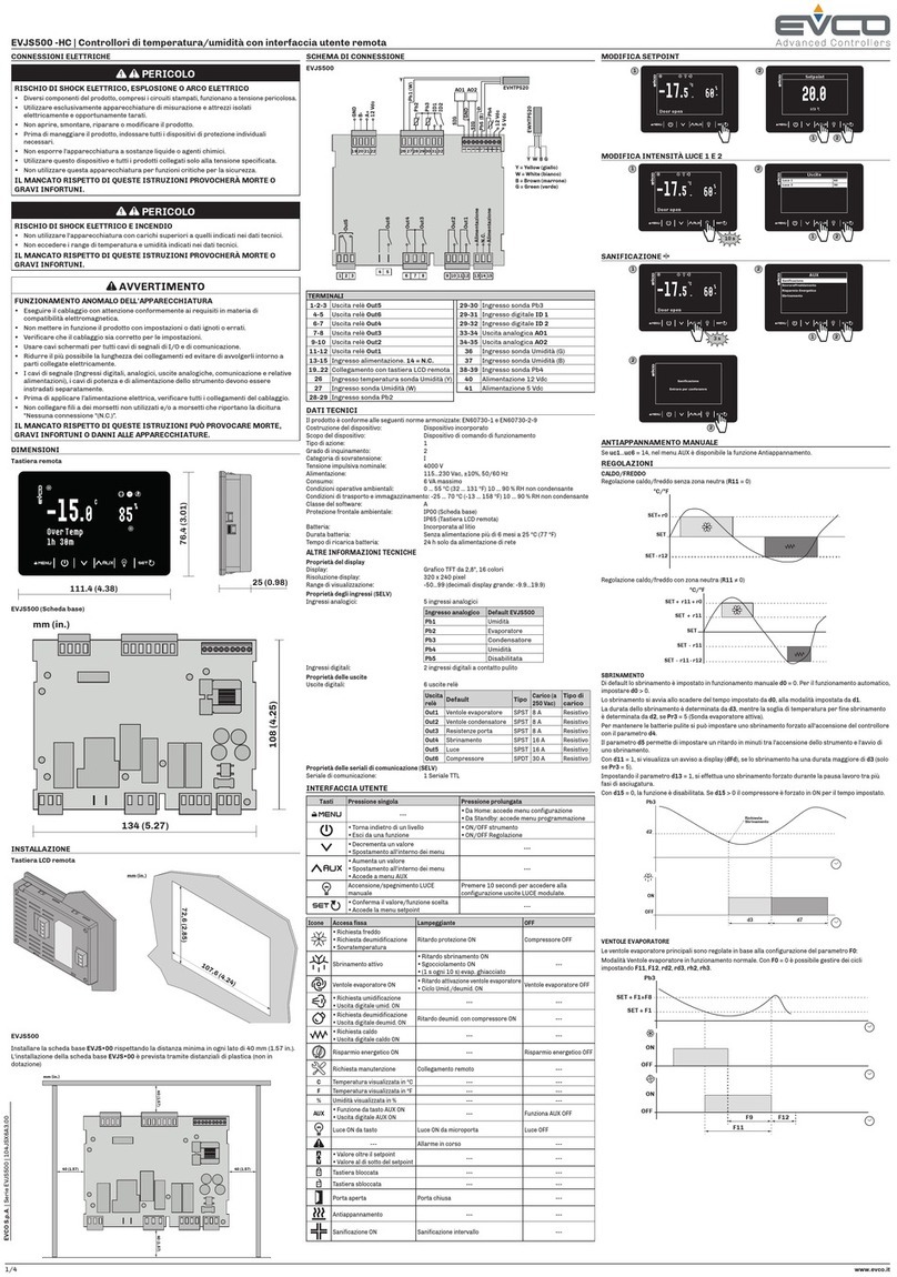
Evco EVLJBOX HP Sequencer User manual

EVCO | 21.10.2020 | AZ | 1144EJBSI104
EVLJBOX HP
Sequencer
Application Manual:
Heat pump sequencer
|Ready-to-install solution
|LCD colour graphic display
|6 capacitive touch keys
|Electrical panel with full IP65
|Display of the main variables of each
heat pump
|Management of the main equipment functions
|Management of up to 5 heat pumps
|Automatic power modulation
|Maximum number of active units
set by parameter
Applications
Heat pump

EVCO | 21.10.2020 | AZ | 2144EJBSI104
EVLJBOX HP Sequencer - Application manual
IMPORTANT
Read this document carefully before installation and take all precautions before using the device.
Keep this document with the device for future reference.
Only use the device in the ways described in this document.
CONSIDER THE ENVIRONMENT
Please read this document carefully and save it.
DISPOSAL
The device must be disposed of according to local regulations governing the collection of electrical and electronic
equipment.

EVCO | 21.10.2020 | AZ | 3144EJBSI104
EVLJBOX HP Sequencer - Application manual
Index
|Introduction 5
|Purchasing codes 6
|Measurements 7
|Installation 8
|Electrical connections 9
|EVLJBOX HP Sequencer - User interface 9
|Description of connectors 9
|EVLJBOX HP Sequencer - Control module 10
|Description of connectors 10
|Electrical connection 12
|User interface 13
|Keypad 13
|List of pages 14
|Password 14
|Main page 15
|Status pages 17
|Main menu 18
|User menu 18
|Servicer menu 19
|Installer menu 19
|RTC menu 20
|Alarm menu 21
|Alarm history menu 21
|Save/reset menu 21
|Info menu 22
|List of parameters 23
|Description of parameters 23
|Structure of the menus 23
|Conguration parameters table 24
|Regulations 28
|Machine status 28
|Setting the RTC 28
|Main regulation 29
|Slave on/off sequence 31
|Slave status 31
|Mixing valves 31

EVCO | 21.10.2020 | AZ | 4144EJBSI104
EVLJBOX HP Sequencer - Application manual
|Diagnostics 34
|Manual and automatic alarms 34
|Manual alarms 34
|Automatic alarms 34
|Table of alarms 35
|Blocking alarms for the master 35
|Blocking alarms for the slaves 35
|Slave conguration alarm 37
|Slave communication alarm 37
|Evaporator high/low temperature alarm 38
|Condenser high/low temperature alarm 39
|Technical specications 40

EVCO | 21.10.2020 | AZ | 5144EJBSI104
EVLJBOX HP Sequencer - Application manual
Introduction
The EVLJBOX HP Sequencer is a control solution housed in an
electric panel that makes it possible to control in sequence up
to 5 heat pumps managed by programmable EVCO devices and
interconnected with RS-485 serial communications systems.
The number of operating units and their power level are adjusted
according to the cooling/heating requirements of the equipment,
but it is also possible to set parameters for the number of units
active at the same time.
The fully IP65-compliant panel houses a user interface with a LCD
graphic display with a resolution of 320x240 pixels and 16 colours,
from which it is possible to manage all the main functions of the
equipment (switch on/off, alter operating mode, etc.) and view the
main variables of each of the connected heat pumps.

EVCO | 21.10.2020 | AZ | 6144EJBSI104
EVLJBOX HP Sequencer - Application manual
Purchasing codes
The table below shows the main features of the EVLJBOX HP Sequencer model available and the relative purchasing code
Features Models
Power supply
115... 230 VAC •
Analogue digital inputs
Evaporator supply water temperature probe (PTC/NTC/PT1000) •
Evaporator return water temperature probe (PTC/NTC/PT1000) •
Condenser supply water temperature probe (PTC/NTC/PT1000) •
Condenser return water temperature probe (PTC/NTC/PT1000) •
Analogue outputs
Evaporator mixing valve (0-10 V/PWM) •
Condenser mixing valve (0-10 V/PWM) •
Digital outputs
Heating/cooling switching valve 1 5 A
Heating/cooling switching valve 2 5 A
User interface
320x240 px with LCD colour graphic display •
Dimensions
150x245 mm •
Installation
Wall mounted •
Connections
Fixed screw terminal blocks •
Type A female USB connector •
Communications ports
RS-485 MODBUS MASTER 1
USB 1
Further features
Clock •
For more information see the section “Technical specications”
Description of purchasing codes
Features Code
115... 230 VAC - LCD graphic display - Wall mounted - RS-485 MODBUS - USB - Clock

EVCO | 21.10.2020 | AZ | 7
004_EVLJBOX_Sequencer_Dimensioni_001_0.1_AZ
144EJBSI104
EVLJBOX HP Sequencer - Application manual
Measurements
150 mm 88.6 mm
245 mm

EVCO | 21.10.2020 | AZ | 8
008_EVLJBOX_Sequencer_Installazione_001_0.1_AZ
008_EVLJBOX_Sequencer_Installazione-02_001_0.1_AZ
c-pro 3 OEM
144EJBSI104
EVLJBOX HP Sequencer - Application manual
Installation
INSTALLATION PRECAUTIONS
–Ensure that the working conditions are within the limits stated in the “Technical specications” section.
–Do not install the device close to heat sources, equipment with a strong magnetic eld, in places subject to direct
sunlight, rain, damp, excessive dust, mechanical vibrations or shocks.
–In compliance with safety regulations, the device must be installed properly to ensure adequate protection from
contact with electrical parts. All protective parts must be xed in such a way as to need the aid of a tool to remove
them.
–Users will need a rigid pipe tting; the maximum diameter of the xing hole must be 28.5 mm
–To ensure IP65-rated protection of the whole casing, x the container using only the holes already made
Wall mounting
1. Secure the back cover |7| to the wall using the 4 screws
|1|
and the holes already made |6|
2. Make sure the seal |8| is correctly inserted
3. Place the front cover |4| over the back cover
|7| and push the 2 assembling tongues |10|
down into the holes |2| on the right or left
of the front cover |4|
4. Fix the user interface |12| into place by pressing it
into its housing |5| from the front
5. Fix the control module |14| to the DIN rail |16|;
next secure the DIN rail |16| to the back cover
|7| in its housing |17| with two screws |15|
6. If the connection cables are fed in from above,
make a hole whose diameter is suitable for xing
a rigid pipe tting |13| on the top of the
back cover |7|; if the cables are fed in from the
bottom, make the hole on the bottom of the cover
7. Screw the rigid pipe tting |13| to the back
cover |7|
8. Connect the user interface |12| as shown in the
section “Electrical connections”, feeding the
connection cables through the rigid pipe tting |13|
9. Secure the front cover |4| to the back cover |7|
using the 4 screws |9| and the holes already made |3|
10. Fix the covering strips |11| over the top and bottom
parts of the front cover |4|
74
5
1
9 13
1514 16
17
17
10 11 12
2 6 8
3

EVCO | 21.10.2020 | AZ | 9
4
3
2
1
EVJBOX HP
Sequencer
12
ON
002_EPJgraph_Pannello_DescrizConnettori_001_0.1_AZ
144EJBSI104
EVLJBOX HP Sequencer - Application manual
Electrical connections
PRECAUTIONS FOR ELECTRICAL CONNECTIONS
–Use cables of an adequate section for the current running through them
–To reduce any electromagnetic interference, connect the power cables as far away as possible from the signal cables
and connect to a RS-485 MODBUS network using a twisted pair
–If using an electrical or pneumatic screwdriver, adjust the tightening torque
–If the device is moved from a cold to a warm place, humidity may cause condensation to form inside; wait for about an
hour before switching on the power
–Make sure that the supply voltage, electrical frequency and power are within the set limits
–Disconnect the power supply before carrying out any type of maintenance
–Do not use the device as a safety device
–For repairs and further information, contact the EVCO sales network; returned goods without the data label will not be
accepted
Connector 2
Micro-switch
Connector 1
User interface
Connector 1
Number Description
1- signal CAN port
2+ signal CAN port
3
Device power supply (24 VAC/12... 30 VDC): if the
device is powered by direct current, connect the
negative terminal
4
Device power supply (24 VAC/12... 30 VDC): if the
device is powered by direct current, connect the
positive terminal
Connector 2
Number Description
1For EVCO use only
Micro-switch
Number Description
2To terminate the CAN network
1For EVCO use only
EVLJBOX HP Sequencer - User interface
Description of connectors

EVCO | 21.10.2020 | AZ | 10
CO1
AO4AO3 AO2AO1 DI4DI3 IN7IN6 IN5IN4 IN3IN2 IN1GND 12VS 5VS IB
NO1 CO2NO2 CO3 NO3 CO4NO4 CO5 NO5 NO6CO6 NC6DIHV1DIHV1DIHV2DIHV2ACAC
GND CAN+ CAN-
A/+ B/-
002_EVLJBOX_Sequencer_Connettori_001_0.1_AZ
EVLJBOX HP Sequencer
21
ON
144EJBSI104
EVLJBOX HP Sequencer - Application manual
EVLJBOX HP Sequencer - Control module
Description of connectors
Connector 1
Number Description
CO1 K1 digital output common contact
NO1 K1 digital output normally open contact
(5 A res. at 250 VAC)
CO2 K2 digital output common contact
NO2 K2 digital output normally open contact
(5 A res. at 250 VAC)
CO3 K3 digital output common contact
NO3 K3 digital output normally open contact
(5 A res. at 250 VAC)
Connector 2
Number Description
CO4 K4 digital output common contact
NO4 K4 digital output normally open contact
(5 A res. at 250 VAC)
CO5 K5 digital output common contact
NO5 K5 digital output normally open contact
(5 A res. at 250 VAC)
Connector 3
Number Description
NO6 K6 digital output normally open contact
(16 A res. at 250 VAC)
CO6 K6 digital output common contact
NC6 K6 digital output normally closed contact
Connector 4
Number Description
DIHV1 DI1 high voltage digital input
DIHV2 DI2 high voltage digital input
Connector 8
Connector 1 Connector 2 Connector 4
Connector 3 Connector 5
Connector 6
Connector 7
Connector 5
Number Description
AC Device power supply (115... 230 VAC)
Connector 6
Number Description
IB INTRABUS port data
GND Reference (GND)
A/+ If installed, + signal
RS-485 MODBUS master/slave port
B/- If installed, - signal
RS-485 MODBUS master/slave port
CAN+ + signal CAN port
CAN- - signal CAN port
Control module

EVCO | 21.10.2020 | AZ | 11144EJBSI104
EVLJBOX HP Sequencer - Application manual
Connector 7
Number Description
USB USB port to programme the device
Connector 8
Number Description
AO4 AO4 analogue output (for 0-10 V or PWM signal)
AO3 AO3 analogue output (for 0-10 V or PWM signal)
AO2 AO2 analogue output (for 0-10 V or PWM signal)
AO1 AO1 analogue output (for 0-10 V or PWM signal)
DI4 DI4 digital input
(dry contact and for pulse trains up to 2 KHz)
DI3 DI3 digital input
(dry contact and for pulse trains up to 2 KHz)
IN7
AI7 analogue input
(for PTC, NTC or Pt 1000 probes); can also be
congured for DI11 dry contact digital input
IN6
AI6 analogue input
(for PTC, NTC or Pt 1000 probes); can also be
congured for DI10 dry contact digital input
IN5
AI5 analogue input
(for PTC, NTC or Pt 1000 probes); can also be
congured for DI9 dry contact digital input
IN4
AI4 analogue input
(for PTC, NTC or Pt 1000 probes); can also be
congured for DI8 dry contact digital input
IN3
AI3 analogue input
(for NTC probes, 0-5 V, 0-10 V, 0-20 mA or 4-20 mA
transd.); can also be congured for DI7 dry contact
digital input
IN2
AI2 analogue input
(for NTC probes, 0-5 V, 0-10 V, 0-20 mA or 4-20 mA
transd.); can also be congured for DI6 dry contact
digital input
IN1
AI1 analogue input
(for NTC probes, 0-5 V, 0-10 V, 0-20 mA or 4-20 mA
transd.); can also be congured for DI5 dry contact
digital input
GND Reference (GND)
12VS Auxiliary power supply (12 VDC)
5VS 0-5 V ratiometric transducers power supply (5
VDC)

EVCO | 21.10.2020 | AZ | 12144EJBSI104
EVLJBOX HP Sequencer - Application manual
Electrical connection
Condenser mixing valve
Heating/cooling switching valve 1
Heating/cooling switching valve 2
heat pump
EVCO 5
heat pump
EVCO 4
heat pump
EVCO 3
heat pump
EVCO 2
heat pump
EVCO 1
Evaporator mixing valve
Condenser return water temp. probe
Condenser supply water temp. probe
Fan return water temp. probe
Fan supply water temp. probe
Mains supply
(230 VAC)
Power supply
(115... 230 VAC)
Control module
User interface

EVCO | 21.10.2020 | AZ | 13
005_EVLJBOX_Sequencer_InterfacciaUtente_001_0.1_AZ
OFF DA TASTO
Comunicazione con
slave non attiva
144EJBSI104
EVLJBOX HP Sequencer - Application manual
User interface
Keypad
Description of keys
Keys Instructions
ON/STAND-BY
LEFT AND RIGHT
UP AND DOWN
ENTER
Description of LEDs
LED Instructions
ON/STAND-BY
ALARM
POWER
Switching the device on/off
Steps Description
1
Connect to the power supply:
an internal test will start up which will take a
couple of seconds
2Hold the ENTER key down for 2 seconds:
the display will show the main screen
3To switch off the device, disconnect it from the
power supply
Access to menus
Keys Instructions
Hold the ENTER key down for 2 seconds:
the display will show the main screen
Press the UP or DOWN key to select the menus
Press the ENTER key to conrm the menu
Press the ENTER key to access the value
Press the UP or DOWN key to set the value
Press the ENTER key to conrm the value
Press the ON/STAND-BY key a few times to return
to the previous displays
Passwords
Keys Instructions
Hold the ENTER key down for 2 seconds:
the display will show the main screen
Press the DOWN key:
the display will show the menu
Press the ENTER key to conrm the menu.
The display will show “enter password”
Press the ENTER key to access the “password”
value
Press the UP or DOWN key to set the password
Press the ENTER key to conrm

EVCO | 21.10.2020 | AZ | 14144EJBSI104
EVLJBOX HP Sequencer - Application manual
List of pages
This section lists the main pages and menus used in the application.
The main menu has three levels:
–User
–Servicer
–Installer
USER menu - Level 1
–Operating mode
–Summer setting
–Winter setting
–User password
SERVICER menu - Level 2 (PW=1)
–Counters
–I/O tests
–Calibration
–Input/output
–Password
INSTALLER menu - Level 3 (PW=2)
–Conguration
–Regulation
–Evaporator mixing valve section
–Condenser mixing valve section
–Security
–CAN
–MODBUS
–Default
–Miscellaneous
–Password
RTC menu - Level 0
ALARM menu - Level 0
–Master
–Slave
HISTORY menu - Level 0
SAVE/RESET menu - Level 0
–Flash drive
–Memory
INFO menu - Level 0
Password
Each menu level sets the accessibility to the various functions and it is assigned a password.
Once the correct password has been entered, users can:
–Access protected functions
–Unlock the level in question
–Unlock the various sublevels
Level passwords can be changed by the same or higher levels.
Passwords of all the levels can be changed from the INSTALLER level.
The range of possible values to set passwords goes from -999/9999.
The password setting time frame expires after 4 minutes, after which it is necessary to set a new password.

EVCO | 21.10.2020 | AZ | 15
005_EVLJBOX_Sequencer_SchermataHome_001_0.1_AZ
OFF DA TASTO
Comunicazione con
slave non attiva
005_EVLJBOX_Sequencer_SchermataSistemaSpento_001_0.1_AZ
ALLARMI ATTIVI : 0
11/06/2019 15:00
VERSIONE SW: 1.1
AVVIO SISTEMA
005_EVLJBOX_Sequencer_SchermataInizzializ_001_0.1_AZ
ALLARMI ATTIVI : 0
11/06/2019 15:00
VERSIONE SW: 1.1
AVVIO SISTEMA
Inizializzazione...
144EJBSI104
EVLJBOX HP Sequencer - Application manual
Main page
Viewing of the “main page” changes according to machine
status:
–If the sequencer is on “OFF by key” or “OFF by alarm”
–If the system is off or on
If a fault occurs in the control probe, the sequencer will go
into the “OFF by alarm” state.
The control probe alarm, AL13 if the probe is that of the
evaporator or AL15 if the probe is that of the condenser,
has manual reset. Once the fault has been xed and the
alarm reset, the sequencer will automatically return to the
condition prior to the alarm.
If the sequencer is on “OFF by key” or “OFF by alarm”,
MODBUS communication with the slaves is disabled. After
5 minutes, they will begin working autonomously and
independently.
When the “ON/STAND-BY” key is pressed for 2 seconds,
MODBUS communication with the slaves will begin.
The “system off page” will be displayed on the sequencer
with the following information:
–Active alarms in the master and relative number
–= no alarm active
–= at least one alarm active
–Current date and time
–Software version
–Command to switch on the sequencer system
To prevent the sequencer being accidentally switched on,
which could cause problems with the sensitive MODBUS
communication, press the “DOWN” key before switching it
on. The message “SYSTEM START-UP” will appear, press the
“ENTER” key to conrm.
Users can browse the machine status pages from this page
using the “LEFT” and “RIGHT” keys:
–Master
–Slave
By holding down the “ON/STAND-BY” key for 2 seconds
on this page only, it is possible to disable MODBUS
communication with the slaves.
Machine status will therefore be in “OFF by key”.
If the sequencer is started up and MODBUS communication
with all the slaves has not yet been established, the word
“Initialisation” will ash underneath.
Once communication has been established, the sequencer’s
ON page will automatically be loaded.
“main page”
with sequencer in
“OFF by key”
“system off page”
with sequencer off
Sequencer switched on
awaiting “Initialisation” of
MODBUS communication with
the slaves

EVCO | 21.10.2020 | AZ | 16
005_EVLJBOX_Sequencer_SchermataCondAcqua_001_0.1_AZ
MASTER: SLAVES: 3 Att.
Potenza richiesta:
Potenza resa:
65 %
60 %
Condens.
STOP SISTEMA
17.7 °C
Evap.
36.5 °C
005_EVLJBOX_Sequencer_SchermataCondAria_001_0.1_AZ
MASTER: SLAVES: 3 Att.
Potenza richiesta:
Potenza resa:
65 %
60 %
STOP SISTEMA
Evap.
36.5 °C
144EJBSI104
EVLJBOX HP Sequencer - Application manual
When the sequencer is switched on, two main screens are
available depending on the type of condenser congured in
the slaves:
–If it is a water condenser
the output temperature of both the
condenser and the evaporator will be
displayed
–If it is an air condenser
only the evaporator temperature will be displayed
The following information is available on the main pages:
–Master status:
–= no alarm active
–= at least one minor alarm active
–= at least one blocking alarm active
–Number of active slaves
if an alarm occurs with one of the slaves,
the alarm icon will ash every 2 seconds
–= minor alarm
–= blocking alarm
–Condenser output temperature
shown only with slave with water condenser
–Evaporator output temperature
–Power required by the system
–System power output
–Command to switch sequencer off
If there is an error with a probe or if it is disconnected, “---”
will appear in the eld for that value.
To prevent the sequencer being accidentally switched off,
which could cause problems with the sensitive MODBUS
communication, press the “DOWN” key before switching
it off. The message “STOP SYSTEM” will appear, press the
ENTER” key to conrm.
When the “LEFT” and “RIGHT” keys are pressed on the
“main page” , information concerning the following will be
displayed in sequence:
–Master
–Congured slaves
–Mixing valves in the system
Pressing the “ON/STAND-BY” key from the main page will
take you back to the “Alarm/History” page.
“main page”
slave with water condenser
“main page”
slave with air condenser

EVCO | 21.10.2020 | AZ | 17
005_EVLJBOX_Sequencer_Schermata_Master_001_0.1_AZ
T. regolazione: 28.0 °C
Setpoint: 24.0 °C | ZN: 3.0 °C
Potenza richiesta:
Potenza resa:
45 %
33 %
Slave attivi: 2/5
Modalità funz.: Estate
MASTER
005_EVLJBOX_Sequencer_Schermata_Slave_001_0.1_AZ
SLAVE
STATO: ATTIVO
Stato unità:
Ore funzionamento:
Potenza richiesta:
Potenza resa:
ON
10 H
80 %
66 %
Cmp attivi: 2
144EJBSI104
EVLJBOX HP Sequencer - Application manual
Status pages
“Master screen”
When the “LEFT” and “RIGHT” keys are pressed on the
“system off” or “system on“ screens, the individual status
pages of only the congured slaves and mixing valves
installed will be displayed.
The “master screen” will always be displayed.
This screen displays the following information regarding the
master:
–Master status
–= no alarm active
–= at least one minor alarm active
–= at least one blocking alarm active
–Operating mode
–= summer/cooling
–= winter/heating
–Temperature of regulation probe
–Current setpoint and regulation neutral zone
–Power required by the master
–Slave power output
–Number of active slaves
“Slave screen”
This screen displays the following information regarding
each slave:
–Slave status
–= no alarm active
–= at least one minor alarm active
–= at least one blocking alarm active
–Regulation status
–ALARM = at least one blocking alarm is active
in the slave
–UNIT OFF = slave off
–READY = slave enabled and ready for regulation
–ACTIVE = slave currently used by regulation
–FULL POWER = slave adjusted to maximum
power
–Unit status
–OFF KEY = slave switched off by a key
–OFF DI = slave switched off by a digital input
–OFF supervisor = slave switched off by the
supervision protocol
–OFF changeover = slave switched off due to an
operating mode changeover
–OFF defrost = slave switched off for defrosting
–OFF programme = slave switched off by time
bands programme
–OFF alarm = slave switched off by alarm
–OFF RTC = slave switched off due to RTC fault or
dead battery
–ON = slave on
–Slave operating hours
–Power requested to slave
–Slave power output
–Number of active compressors
“master screen”
“slave screen”

EVCO | 21.10.2020 | AZ | 18
005_EVLJBOX_Sequencer_Schermata_ValvolaEv_001_0.1_AZ
Temperatura:
Setpoint:
Differenziale:
Richiesta:
AO:
34.0 °C
30.0 °C
10.0 °C
40 %
40 %
VMIX EVAPORATORE
005_EVLJBOX_Sequencer_Schermata_ValvolaCon_001_0.1_AZ
Temperatura:
Setpoint:
Differenziale:
Richiesta:
AO:
46.0 °C
40.0 °C
10.0 °C
60 %
60 %
VMIX CONDENSATORE
UTENTE
005_EVLJBOX_Sequencer_Schermata_MenuUtente_001_0.1_AZ
Modo funz.:
Set estivo:
Set invernale:
Password utente
Estate
24.0 °C
40.0 °C
0
005_EVLJBOX_Sequencer_Schermata_MenuGenerale_Pag2_001_0.1_AZ
MENU
SALVA/RIPRIS.
Pag. 2/2Prec.
INFO
005_EVLJBOX_Sequencer_Schermata_MenuGenerale_001_0.1_AZ
MENU
UTENTE
RTC
Pag. 1/2 Succ.
ALLARMISTORICO
MANUTENTORE INSTALLATORE
144EJBSI104
EVLJBOX HP Sequencer - Application manual
“Evaporator mixing valve screen”
This screen displays the following information regarding the
evaporator valve:
–Temperature of regulation probe
–Current regulation setpoint
–Regulation differential
–Regulation request
–Analogue output valve value
“Condenser mixing valve screen”
This screen displays the following information regarding the
condenser valve:
–Temperature of regulation probe
–Current regulation setpoint
–Regulation differential
–Regulation request
–Analogue output valve value
“evaporator mixing valve
screen”
“condenser mixing valve
screen”
“user menu”
Main menu
The “main menu” has no level and is the access point for all
the other system menus.
It is possible to view the “main menu” from any point on the
user interface by pressing “ENTER” for about 2 seconds.
It is possible to access the desired function by pressing the
“UP” and “DOWN” keys from the “main menu”.
Press the “ENTER” key to conrm.
User menu
The “user menu” is level 1 and it is therefore necessary to
enter the user level password (or that of a higher level) to
view/change the parameters in this section.
This section contains the following parameters:
- Operating mode
- Setpoint for summer operation
- Setpoint for winter operation
- User password
“main menu” page 1
“main menu” page 2

EVCO | 21.10.2020 | AZ | 19
MANUTENTORE
005_EVLJBOX_Sequencer_Schermata_MenuManutentore_001_0.1_AZ
INPUT/OUTPUT PASSWORD
FORZATURECALIBRAZIONE
CONTATORI
INSTALLATORE
005_EVLJBOX_Sequencer_Schermata_MenuInstallatore_001_0.1_AZ
VMIX COND. SICUREZZE
REGOLAZIONE VMIX EVAP.
CAN
CONFIG.
Pag. 1/
2S
ucc.
25K
50K
125K
500K
INSTALLATORE
005_EVLJBOX_Sequencer_Schermata_MenuInstallatore_Pag2_001_0.1_AZ
VARI
DEFAULT
PASSWORD
MODBUS
Pag. 2/2Prec.
144EJBSI104
EVLJBOX HP Sequencer - Application manual
“servicer menu”
Servicer menu
The “servicer menu” is level 2 and it is therefore necessary
to enter the servicer level password (or that of a higher
level) to view/change the parameters in this section.
It is possible to view the status of the various devices and
the inputs/outputs used by the application in this menu.
This section contains the following menus:
–“counters menu”
the operating hours of the master and slaves can be
viewed here
–“I/O test menu”
simulation of the analogue inputs, the analogue
outputs and the digital outputs can be enabled here.
–“calibration menu”
corrections to be applied to the analogue inputs to
compensate for the offsets due to the cabling and
probe position can be set here
–“input/output menu”
the physical board inputs and outputs can be viewed
directly here
–“password menu”
the servicer level (level 2) password can be set here
Installer menu
The “installer menu” is level 3 and it is therefore necessary
to enter the installer level password (or that of a higher
level) to view/change the parameters in this section.
All the parameters regarding the conguration of the
functions can be found in the “installer menu”, including:
–Alarms
–Regulations
–Logics
–Features
This section contains the following menus:
–“conguration menu”
the following actions can be carried out in this menu:
–set the total number of slaves to control
–set the number of slaves in stand-by
–enable the evaporator and condenser mixing valves
Changes to these parameters may cause problems with
MODBUS communication with the slaves, so this menu
can only be accessed when the machine is in “OFF by
key” or “OFF by alarm”
–“regulation menu”
the main regulation parameters can be set in
this menu:
–regulation neutral zone
–time and percentage of increase/decrease of
regulation in
the neutral zone
–consecutive operating time after which the
slaves must be rotated
–inversion of the analogue inputs/outputs of the
mixing valves in winter mode
–“VMIX evaporator/condenser menu ”
“installer menu ” page 1
“installer menu ” page 2

EVCO | 21.10.2020 | AZ | 20
IMPOSTAZIONE RTC
005_EVLJBOX_Sequencer_Schermata_MenuRTC_001_0.1_AZ
13/06/2019 10:00:00
144EJBSI104
EVLJBOX HP Sequencer - Application manual
the parameters to manage the evaporator and
condenser
mixing valves can be set in this menu
–“safety menu”
all the parameters regarding the sequencer alarms can
be found in this menu:
–high/low temperature alarm setpoint and
differentials
–enabling
–signalling delays
–re-arm type
–“CAN menu”
all the parameters to congure the CAN network
can be viewed in this menu
–“MODBUS menu”
all the parameters to congure the network on
the RS-485 port can be viewed in this menu
–“default menu”
the default values of all the application parameters
can be reset in this menu
–“miscellaneous menu”
this contains other general parameters such as:
–enabling system start-up/stop by the supervisor
–setting the language
–setting the temperature measurement unit
–deleting history
–setting the minimum and maximum threshold values
–“password menu”
the installer (level 3) password can be set in this
menu
“RTC menu”
RTC menu
The “RTC menu” contains all the functions of the RTC (Real
Time Clock) system.
Table of contents
Other Evco Control System manuals
Popular Control System manuals by other brands

Infinity
Infinity Sidekick V1 user manual

Techtrol
Techtrol VLC Installation & operational manual

PendoTECH
PendoTECH PressureMAT PMAT1 user guide

DX Engineering
DX Engineering Top Ten Devices OPSWAPPER quick start guide

Mitsubishi Electric
Mitsubishi Electric MELDAS FCU6-DX561 Maintenance manual

btsr
btsr MULTIFEEDER operating manual