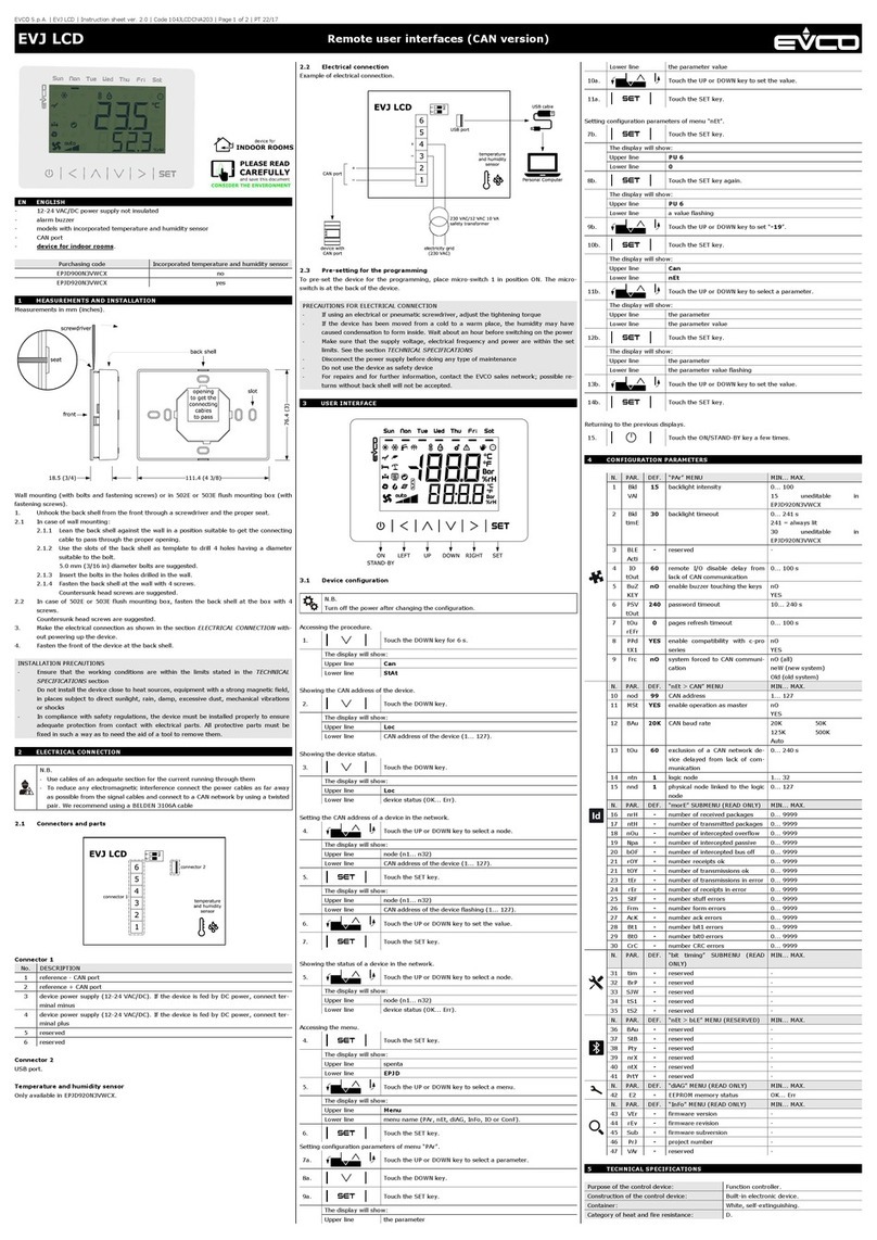
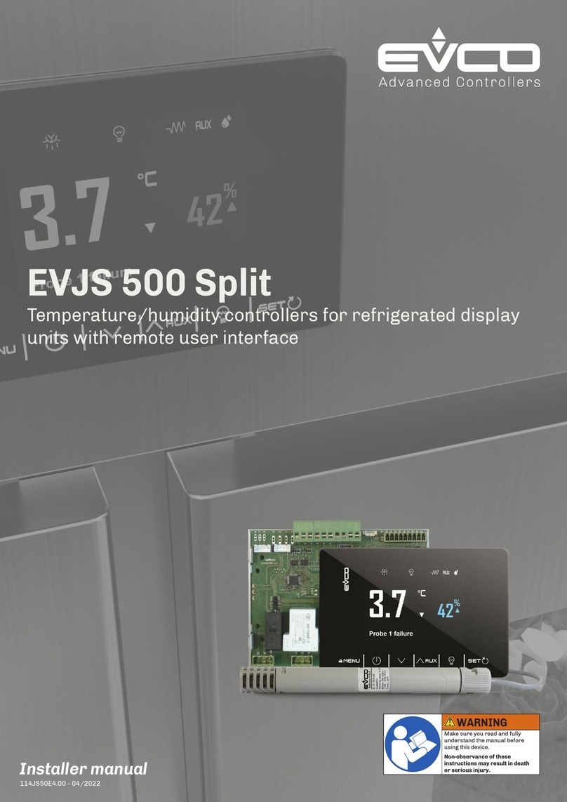
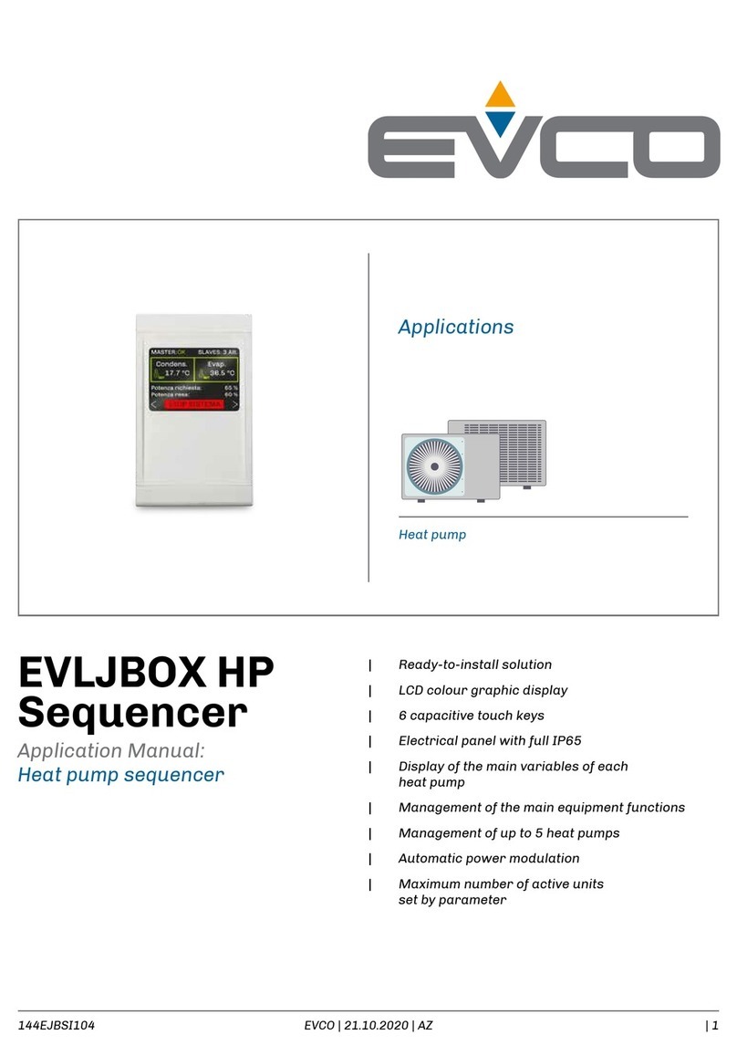
Evco EVJS500 User manual

EVCO S.p.A. | Serie EVJS500 | 104JSX6A3.00
www.evco.it
EVJS500 -HC | Controllori di temperatura/umidità con interfaccia utente remota
1/4
CONNESSIONI ELETTRICHE
PERICOLO
RISCHIO DI SHOCK ELETTRICO, ESPLOSIONE O ARCO ELETTRICO
• Diversi componenti del prodotto, compresi i circuiti stampati, funzionano a tensione pericolosa.
• Utilizzare esclusivamente apparecchiature di misurazione e attrezzi isolati
elettricamente e opportunamente tarati.
• Non aprire, smontare, riparare o modificare il prodotto.
• Prima di maneggiare il prodotto, indossare tutti i dispositivi di protezione individuali
necessari.
• Non esporre l'apparecchiatura a sostanze liquide o agenti chimici.
• Utilizzare questo dispositivo e tutti i prodotti collegati solo alla tensione specificata.
• Non utilizzare questa apparecchiatura per funzioni critiche per la sicurezza.
IL MANCATO RISPETTO DI QUESTE ISTRUZIONI PROVOCHERÀ MORTE O
GRAVI INFORTUNI.
PERICOLO
RISCHIO DI SHOCK ELETTRICO E INCENDIO
• Non utilizzare l'apparecchiatura con carichi superiori a quelli indicati nei dati tecnici.
• Non eccedere i range di temperatura e umidità indicati nei dati tecnici.
IL MANCATO RISPETTO DI QUESTE ISTRUZIONI PROVOCHERÀ MORTE O
GRAVI INFORTUNI.
AVVERTIMENTO
FUNZIONAMENTO ANOMALO DELL'APPARECCHIATURA
• Eseguire il cablaggio con attenzione conformemente ai requisiti in materia di
compatibilità elettromagnetica.
• Non mettere in funzione il prodotto con impostazioni o dati ignoti o errati.
• Verificare che il cablaggio sia corretto per le impostazioni.
• Usare cavi schermati per tutti cavi di segnali di I/O e di comunicazione.
• Ridurre il più possibile la lunghezza dei collegamenti ed evitare di avvolgerli intorno a
parti collegate elettricamente.
• I cavi di segnale (Ingressi digitali, analogici, uscite analogiche, comunicazione e relative
alimentazioni), i cavi di potenza e di alimentazione dello strumento devono essere
instradati separatamente.
• Prima di applicare l’alimentazione elettrica, verificare tutti i collegamenti del cablaggio.
• Non collegare fili a dei morsetti non utilizzati e/o a morsetti che riportano la dicitura
“Nessuna connessione “(N.C.)”.
IL MANCATO RISPETTO DI QUESTE ISTRUZIONI PUÒ PROVOCARE MORTE,
GRAVI INFORTUNI O DANNI ALLE APPARECCHIATURE.
DIMENSIONI
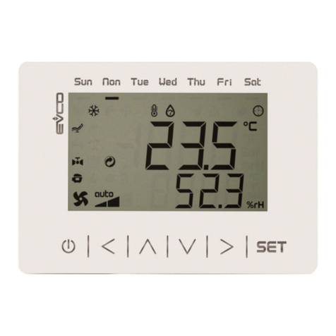
Tastiera remota
-15.085
%
Over
Temp
1h 30m
c
111.4 (4.38)
76.4 (3.01)
25 (0.98)
EVJS500 (Scheda base)
134 (5.27)
mm (in.)
108 (4.25)
INSTALLAZIONE
Tastiera LCD remota
1
0
7
,
6
(4.
24
)
72,6 (2.85)
mm (in.)
EVJS500
Installare la scheda base EVJS•00 rispettando la distanza minima in ogni lato di 40 mm (1.57 in.).
L'installazione della scheda base EVJS•00 è prevista tramite distanziali di plastica (non in
dotazione)
40 (1.57) 40 (1.57)
mm (in.)
40 (1.57) 40 (1.57)
SCHEMA DI CONNESSIONE
EVJS500
GND
Out1
Out2
Out3
Out4
Out6
Out5
B-
A+
12 Vdc
Y
Pb1 (W)
Pb5 (B)
G
EVHTP520
Pb2
Pb3
ID1
ID2
Y = Yellow (giallo)
W = White (bianco)
B = Brown (marrone)
G = Green (verde)
Y W B G
EWHTP520
19 20 21 22 26 27 28 29 30 31 32 33 34 35 36 37 38 39 40 41
910 11 12 13 14 15
123678
45
Pb4
AO1 AO2
GND
SIG
SIG
}
5 Vdc
12 Vdc
Alimentazione
Alimentazione
N.C.
TERMINALI
1-2-3 Uscita relè Out5 29-30 Ingresso sonda Pb3
4-5 Uscita relè Out6 29-31 Ingresso digitale ID 1
6-7 Uscita relè Out4 29-32 Ingresso digitale ID 2
7-8 Uscita relè Out3 33-34 Uscita analogica AO1
9-10 Uscita relè Out2 34-35 Uscita analogica AO2
11-12 Uscita relè Out1 36 Ingresso sonda Umidità (G)
13-15 Ingresso alimentazione. 14 = N.C. 37 Ingresso sonda Umidità (B)
19..22 Collegamento con tastiera LCD remota 38-39 Ingresso sonda Pb4
26
Ingresso temperatura sonda Umidità (Y)
40 Alimentazione 12 Vdc
27 Ingresso sonda Umidità (W) 41 Alimentazione 5 Vdc
28-29 Ingresso sonda Pb2
DATI TECNICI
Il prodotto è conforme alle seguenti norme armonizzate: EN60730-1 e EN60730-2-9
Costruzione del dispositivo: Dispositivo incorporato
Scopo del dispositivo: Dispositivo di comando di funzionamento
Tipo di azione: 1
Grado di inquinamento: 2
Categoria di sovratensione: I
Tensione impulsiva nominale: 4000 V
Alimentazione: 115...230 Vac, ±10%, 50/60 Hz
Consumo: 6 VA massimo
Condizioni operative ambientali: 0 ... 55 °C (32 ... 131 °F) 10 … 90 % RH non condensante
Condizioni di trasporto e immagazzinamento: -25 ... 70 °C (-13 ... 158 °F) 10 … 90 % RH non condensante
Classe del software: A
Protezione frontale ambientale: IP00 (Scheda base)
IP65 (Tastiera LCD remota)
Batteria: Incorporata al litio
Durata batteria: Senza alimentazione più di 6 mesi a 25 °C (77 °F)
Tempo di ricarica batteria: 24 h solo da alimentazione di rete
ALTRE INFORMAZIONI TECNICHE
Proprietà del display
Display: Grafico TFT da 2,8", 16 colori
Risoluzione display: 320 x 240 pixel
Range di visualizzazione: -50...99 (decimali display grande: -9.9...19.9)
Proprietà degli ingressi (SELV)
Ingressi analogici: 5 ingressi analogici
Ingresso analogico Default EVJS500
Pb1 Umidità
Pb2 Evaporatore
Pb3
Condensatore
Pb4
Umidità
Pb5
Disabilitata
Ingressi digitali: 2 ingressi digitali a contatto pulito
Proprietà delle uscite
Uscite digitali: 6 uscite relè
Uscita
relè
Default Tipo
Carico (a
250 Vac)
Tipo di
carico
Out1 Ventole evaporatore SPST 8 A Resistivo
Out2 Ventole condensatore SPST 8 A Resistivo
Out3 Resistenze porta SPST 8 A Resistivo
Out4 Sbrinamento SPST 16 A Resistivo
Out5 Luce SPST 16 A Resistivo
Out6 Compressore SPDT 30 A Resistivo
Proprietà delle seriali di comunicazione (SELV)
Seriale di comunicazione: 1 Seriale TTL
INTERFACCIA UTENTE
Tasti Pressione singola Pressione prolungata
--- • Da Home: accede menu configurazione
• Da Standby: accede menu programmazione
• Torna indietro di un livello
• Esci da una funzione
• ON/OFF strumento
• ON/OFF Regolazione
• Decrementa un valore
• Spostamento all'interno dei menu ---
• Aumenta un valore
• Spostamento all'interno dei menu
• Accede a menu AUX
---
Accensione/spegnimento LUCE
manuale
Premere 10 secondi per accedere alla
configurazione uscite LUCE modulate.
• Conferma il valore/funzione scelta
• Accede la menu setpoint ---
Icone Accesa fissa Lampeggiante OFF
• Richiesta freddo
• Richiesta deumidificazione
• Sovratemperatura
Ritardo protezione ON Compressore OFF
Sbrinamento attivo
• Ritardo sbrinamento ON
• Sgocciolamento ON
• (1 s ogni 10 s) evap. ghiacciato
---
Ventole evaporatore ON
•
Ritardo attivazione ventole evaporatore
• Ciclo Umid./deumid. ON
Ventole evaporatore OFF
• Richiesta umidificazione
• Uscita digitale umid. ON --- ---
• Richiesta deumidificazione
• Uscita digitale deumid. ON Ritardo deumid. con compressore ON ---
• Richiesta caldo
• Uscita digitale caldo ON --- ---
Risparmio energetico ON --- Risparmio energetico OFF
Richiesta manutenzione Collegamento remoto ---
CTemperatura visualizzata in °C --- ---
FTemperatura visualizzata in °F --- ---
%
Umidità visualizzata in % --- ---
AUX • Funzione da tasto AUX ON
• Uscita digitale AUX ON --- Funziona AUX OFF
Luce ON da tasto Luce ON da microporta Luce OFF
--- Allarme in corso ---
• Valore oltre il setpoint
• Valore al di sotto del setpoint --- ---
Tastiera bloccata --- ---
Tastiera sbloccata --- ---
Porta aperta Porta chiusa ---
Antiappannamento --- ---
Sanificazione ON Sanificazione intervallo ---
MODIFICA SETPOINT
-17.560
%
Over
Temp
Door open
°c
Setpoint
1
1 2
3
2
20.0
0/50 °C
Setpoint 2
1 2
0
10/95 %
MODIFICA INTENSITÀ LUCE E
-17.560
%
Over
Temp
Door open
°c
Uscite
1
1 2
2
10 s
Luce 1 60
30
Luce 2
SANIFICAZIONE
-17.
5
60
%
Over
Temp
Door open
°c
AUX
1
1 2
2
3 s
Sanificazione
Sovraraffreddamento
Risparmio Energetico
Sbrinamento
2
2
Sanificazione
Entrare per conferamre
ANTIAPPANNAMENTO MANUALE
Se uc1...uc6 = 14, nel menu AUX è disponibile la funzione Antiappannamento.
REGOLAZIONI
CALDO/FREDDO
Regolazione caldo/freddo senza zona neutra (R11 = 0)
SET
°C/°F
SET+ r0
SET - r12
Regolazione caldo/freddo con zona neutra (R11 ≠ 0)
SET
°C/°F
SET + r11 + r0
SET + r11
SET - r11
SET - r11 - r12
SBRINAMENTO
Di default lo sbrinamento è impostato in funzionamento manuale d0 = 0. Per il funzionamento automatico,
impostare d0 > 0.
Lo sbrinamento si avvia allo scadere del tempo impostato da d0, alla modalità impostata da d1.
La durata dello sbrinamento è determinata da d3, mentre la soglia di temperatura per fine sbrinamento
è determinata da d2, se Pr3 = 5 (Sonda evaporatore attiva).
Per mantenere le batterie pulite si può impostare uno sbrinamento forzato all'accensione del controllore
con il parametro d4.
Il parametro d5 permette di impostare un ritardo in minuti tra l'accensione dello strumento e l'avvio di
uno sbrinamento.
Con d11 = 1, si visualizza un avviso a display (dFd), se lo sbrinamento ha una durata maggiore di d3 (solo
se Pr3 = 5).
Impostando il parametro d13 = 1, si effettua uno sbrinamento forzato durante la pausa lavoro tra più
fasi di asciugatura.
Con d15 = 0, la funzione è disabilitata. Se d15 > 0 il compressore è forzato in ON per il tempo impostato.
Pb3
ON
OFF
d3
d2
d7
Richiesta
Sbrinamento
VENTOLE EVAPORATORE
Le ventole evaporatore principali sono regolate in base alla configurazione del parametro F0:
Modalità Ventole evaporatore in funzionamento normale. Con F0 = 0 è possibile gestire dei cicli
impostando F11,F12, rd2, rd3, rh2, rh3.
ON
OFF
F11
F9 F12
ON
OFF
Pb3
SET + F1
SET + F1+F8

EVCO S.p.A. | Serie EVJS500 | 104JSX6A3.00
www.evco.it
EVJS500 -HC | Controllori di temperatura/umidità con interfaccia utente remota
2/4
UMIDITÀ
Regolazione umidità con zona neutra (rd1 > 0 e rh1 < 0)
SET2
rd0
rd1
rh1
rh0
RH
ENERGY SAVING
Lo strumento permette di variare il valore di Setpoint impostando, con il parametro r4 ≠ 0, un
differenziale che si somma al Setpoint temperatura impostato.
Pb1
ON
OFF
SET
SET + r4
ALLARMI
Descrizione Causa Eetti Risoluzione allarme
Sonda 1 Guasta
• Sonda non
funzionante
• Sonda collegata non
correttamente
• Tipo sonda non
corretto
• Visualizzazione allarme a display
• Regolazione compressore in
funzione di C4 e C5
• Regolazione caldo sospesa
• Controllare il tipo di
sonda (PO)
• Controllare il cablaggio
sonda
• Cambiare il tipo di sonda
Sonda 2 Guasta
• Visualizzazione allarme a display
• Se Pb2 = 1, fine sbrinamento è
per timeout
Sonda 3 Guasta
• Visualizzazione allarme a display
• Se Pb3 = 1, ventole condensatore
in parallelo al compressore
• Se Pb3 = 3, AUX OFF
Sonda 4 Guasta
• Visualizzazione allarme a display
• Regolazione AUX sospesa
Sonda 5 Guasta
• Visualizzazione allarme a display
• Regolazione umid./deumid.
sospesa. Per saturazione il
regolatore applica un tempo AH7
prima di generare l'allarme
Allarme di bassa
temperatura Pb1
Temperatura Pb1 < A1
per un tempo A7
• Visualizzazione allarme a display
• Nessun eetto sulla regolazione
Attendere che la
temperatura Pb1 > A1+A11
Allarme di alta
temperatura Pb1
Temperatura Pb1 > A4
per un tempo A7
• Visualizzazione allarme a display
• Nessun eetto sulla regolazione
Attendere che temperatura
Pb1 < A4-A11
Allarme bassa
umidità
Umidità Pb5 > SET2-AH1
per un tempo AH7
• Visualizzazione allarme a display
• Nessun eetto sulla regolazione
Attendere che la temperatura
letta da Pb5 scenda sotto la
soglia di allarme (SET2-AH1)
Allarme alta
umidità
Umidità Pb5 < SET2+AH4
per un tempo AH7
• Visualizzazione allarme a display
• Nessun eetto sulla regolazione
Attendere che la temperatura
letta da Pb5 salga sopra la
soglia di allarme (SET2+AH4)
Allarme porta
aperta
Ingresso digitale
attivato per un tempo
>
i2
• Visualizzazione allarme a display
• Blocca regolatori in base alla
funzione attiva in iC1 = 7, 8 o 9
• Se i2 = -1 l' allarme è
disabilitato;
• Verificare i2 e iP1
Segnalazione
condensatore
surriscaldato
Temperatura
condensatore
>
C6
• Visualizzazione allarme a display
• Nessun eetto sulla regolazione
Verificare C6
Allarme alta
condensazione
Temperatura
condensatore > C7 per
un tempo C8
• Visualizzazione allarme a display
• Blocca compressore
• Spegnere e accendere lo
strumento;
• Verificare C7 e C8
Allarme
ingresso
multifunzione
Ingresso digitale
attivato (iC1 = 2) per un
tempo i5
• Visualizzazione allarme a display
• Nessun eetto sulla regolazione
Verificare i5
Allarme timeout
sbrinamento
Sbrinamento terminato
per timeout anziché per
raggiungimento d2
• Visualizzazione allarme a display
• Nessun eetto sulla regolazione
• Toccare un tasto qualsiasi
• Verificare d2, d3 ed11
Allarme
pressostato
digitale
Attivazione allarme
pressostato causato
dal pressostato digitale
• Visualizzazione allarme a display
• Blocca compressore
• Il regolatore conta dal primo il
numero di eventi i8 nel tempo i6
Verificare e rimuovere la
causa che ha provocato
l’allarme su ingresso digitale
(reset automatico con i6 = 0)
Allarme
termica 1
Ingresso digitale
attivato (iC1 = 5)
• Visualizzazione allarme a display
• Il regolatore conta dal primo il
numero di eventi i8 nel tempo i7
Se i7 = 0 il riarmo è sempre
automatico
Allarme
termica 2
Ingresso digitale
attivato (iC2 = 4)
Allarme
orologio
Allarme orologio (RTC)
non funzionante
Funzioni collegate all'orologio
non presenti o non sincronizzate
con l'orario effettivo
Impostare l'ora corretta.
Se l'errore permane
sostituire lo strumento
(batteria RTC scarica)
Allarme
mancanza
tensione
Mancanza di tensione
per un tempo
>
A10
Registrazione codice PF nello
storico allarmi
Verificare il cablaggio
dell'alimentazione
Blocco
compressori
Ingresso digitale
attivato (iC2 = 5) per un
tempo i5
• Visualizzazione allarme a display
• Blocco compressori
Verificare e rimuovere la
causa che ha provocato
l’allarme su ingresso digitale
(reset automatico con i6 = 0)
Allarme
comunicazione
Mancanza di
comunicazione tra
scheda base ed
interfaccia utente
• Visualizzazione allarme a display
• Nessun eetto sulla regolazione
• Ripristinare la
comunicazione tra scheda
base e interfaccia utente
• Riarmo automatico
TABELLA PARAMETRI UTENTE
Par. Descrizione UM Range
Default PW
Gruppo SETPOINT
SET Setpoint temperatura. °C/°F r1...r2 10,0 ---
SET2
Setpoint umidità. % h1...h2 --- ---
Gruppo INGRESSI ANALOGICI
CA1 Offset temperatura. °C/°F -25,0...25,0 0,0 0
CA2 Offset sonda evaporatore. °C/°F -25,0...25,0 0,0 0
CA3 Offset sonda Pb3. °C/°F -25,0...25,0 0,0 1
CA4 Offset sonda Pb4. °C/°F -25,0...25,0 0,0 1
CA5 Offset sonda Pb5. °C/°F -25,0...25,0 0,0 1
P0 Tipo di sonda. 0= PTC; 1= NTC. --- 0/1 1 1
P1 Abilita decimale in °C. 0= No; 1= Sì. --- 0/1 1 1
P2
Unità di misura temperatura. (N.B.: Questo parametro non
converte i valori, quindi modificarli manualmente). 0= Celsius;
1= Fahrenheit.
--- 0/1 0 1
Pb2 Abilita sonda evaporatore (Pb2).
0= Disabilitata; 1= Abilitata. --- 0/1 1 1
Pb3 Configurazione sonda 3 (Pb3). 0= Disabilitata;
1= Sonda condensazione; 2= Sonda Ausiliaria; --- 0...2 0 1
Pb4
Configurazione sonda 4 (Pb4). 0= Disabilitato;
1= Sbrinamento 2; 2= Sonda critica; 3= Sonda ausiliaria 2; 4
= 4..20mA (non attivo).
--- 0...4 0 1
Pb5 Abilita sonda umidità (Pb5).
0= Disabilitata; 1= EVHTP520; 2= EVHTP500. --- 0...2 1 1
P3 Segnale analogico minimo. --- 0...100 0 1
P4 Segnale analogico massimo. --- 0...100 100 1
P5
Valore display grande 1. 0= Nessuno (spento);
1= Ingresso 1; 2= Ingresso 2; 3= Ingresso 3;
4 = Ingresso 4; 5 = ingresso 5 (Solo EVJS500);
6= Setpoint 1; 7= Setpoint 2.
--- 0...7 1 1
P6 Valore display piccolo 2. Analogo a P5. --- 0...7 4 1
P8 Tempo rinfresco display 1. Incrementa o decrementa di 1 digit
per intervallo selezionato.
1/10s
0...255 5 1
P9 Tempo rinfresco display 2. Incrementa o decrementa di 1 digit
per intervallo selezionato.
1/10s
0...255 5 1
P20 Modo gestione umidità. 0= Disabilitato; 1= Sonda umidità;
2= Sonda umidità + analogica 1; 3= Analogica 1 fissa. --- 0...3 0 1
Gruppo TEMPERATURA
r0 Differenziale da sommare al setpoint. °C/°F 0,1...25,0 2,0 0
r1 Valore setpoint minimo. °C/°F -30,0...r2 0,0 1
Par. Descrizione UM Range
Default PW
r2 Valore setpoint massimo. °C/°F r1...99,0 50,0 1
r4
Offset setpoint in energy saving sommato al valore di SET.
°C/°F 0,0...99,0 0,0 1
r5 Disabilita regolazione umidità in funzione OverTemp.
0= No; 1= Si. --- 0/1 0 1
r6 Soglia relativa al setpoint temperatura in funzione OverTemp. °C/°F -40,0...99,0 0,0 1
r7 Durata della funzione OverTemp. min 0...240 0 1
r11
Valore zona neutra da aggiungere al differenziale.
•Se r11 > 0, attivo per caldo e Freddo.
•Se r11 < 0 attivo per caldo.
°C/°F -10,0...10,0 0,0 1
r12 Differenziale caldo. °C/°F -25,0...0,1 -2,0 0
r13 Parzializza Uscita Caldo. Verificare gli elementi riscaldanti e al
numero di scambi. 60 = Sempre ON. s 0...60 60 1
R14
Priorità temperatura. Se r14>0 il regolatore smette
di deumidificare con il compressore per sistemare la
temperatura. 0= No; 1= Caldo (se T° sale);
2= Caldo e freddo; 3= Freddo (se T° scende).
--- 0...3 2 1
Gruppo SETPOINT 2
h1 Minimo setpoint 2. % 0...h2 10 1
h2 Massimo setpoint 2. % h1...100 95 1
Gruppo REGOLAZIONE 2 DEUMIDIFICA
rd0 Differenziale deumidificazione. %RH 1...25 3 0
rd1 Zona neutra deumidifica. %RH 0...10 0 1
rd2
Durata ventole accese in deumidificazione con F0 = 0.
s 0...240 60 1
rd3 Durata ventole spente in deumidifica con F0 = 0. s 0...240 0 1
rd4
Deumidifica con compressore o con compressore e caldo. 0=
Disabilitato; 1= Compressore;
2= Compressore e caldo.
--- 0...2 1 1
Gruppo REGOLAZIONE 2 UMIDIFICA
rh0 Differenziale umidificazione. %RH -25...-1 -3 0
rh1 Zona neutra umidifica. %RH 0...10 0 1
rh2 Durata uscita umidificazione 2 accesa (o ventole se uscita RH
non configurata). rh2 = 0 uscita ferma. s 0...240 60 1
rh3
Durata uscita umidificazione spenta (o ventole se uscita RH non
configurata). rh3 = 0 e rh2 > 0 uscita accesa.
s 0...240 0 1
Gruppo COMPRESSORE
C0 Ritardo compressore ON da accensione. min 0...240 0 1
C2 Tempo minimo compressore OFF. min 0...240 3 1
C3 Tempo minimo compressore ON. s 0...240 0 1
C4 Tempo compressore OFF in allarme sonda cella. min 0...240 10 1
C5 Tempo compressore ON in allarme sonda cella. min 0...240 10 1
C6 Temperatura condensazione oltre la quale scatta l'allarme
condensatore surriscaldato. °C/°F 0,0...199 80,0 1
C7 Soglia temperatura condensatore per allarme blocco
compressore, trascorso il tempo C8.°C/°F 0,0...199 90,0 1
C8 Ritardo attivazione allarme blocco compressore da
superamento soglia C7.min 0...15 0 1
C10 Giorni compressore per manutenzione. gg 0....999 0 1
C11 Ritardo ON Compressore 2 da ON Compressore 1. s 0...240 10 1
Gruppo SBRINAMENTO
d0 Intervallo sbrinamento. 0= Disabilitato. h 0...99 8 0
d1 Tipo di Sbrinamento. 0= Elettrico; 1= Inversione. --- 0/1 0 1
d2 Soglia temperatura evaporazione per fine sbrinamento con
sonda evaporatore. °C/°F -99,0...99,0 8,0 0
d2b Soglia fine sbrinamento 2. °C/°F -99,0...99,0 8,0 1
d3 Durata sbrinamento. min 0...99 30 0
d4
Abilitazione sbrinamento all'accensione dispositivo.
0= No; 1= Accensione; 2= Post overcooling;
3= Accensione e post overcooling.
--- 0...3 0 1
d5 Tempo che intercorre tra l'accensione dispositivo e l'avvio
sbrinamento. min 0...99 0 1
d6
Valore visualizzato a display durante uno sbrinamento.
0= Regolazione; 1= Display bloccato; 2= Riservato.
--- 0...2 1 1
d7 Tempo di gocciolamento dell'evaporatore dopo uno
sbrinamento. min 0..15 0 1
d11 Abilitazione avviso sbrinamento terminato per durata
massima (codice dFd). 0 = No; 1= Si. --- 0/1 0 1
d15 Tempo consecutivo compressore ON prima di sbrinamento
gas caldo. min 0...99 0 1
d17 Abilita invio segnalazione evaporatore ghiacciato.
0= No; 1= Si; 2 = Sbrina. --- 0...2 0 1
d18 Intervallo sbrinamento adattativo.
Raggiunta la durata in un ciclo d0. min 0...999 0 1
d19 Differenziale per sbrinamento adattativo su temperatura
evaporatore principale. °C/°F 0...40 0 1
d20
Tempo consecutivo compressore ON per sbrinamento.
min 0...99 0 1
Gruppo ALLARMI
A1 Soglia allarme bassa temperatura. °C/°F -99,0...99,0 0,0 1
A2 Tipo allarme bassa temperatura.
0= Disabilitato; 1= Relativo SET;2 = Assoluto. --- 0...2 2 1
A4 Soglia allarme alta temperatura. °C/°F -99,0...99,0 50,0 1
A5 Tipo allarme alta temperatura.
0= Disabilitato; 1= Relativo SET;2 = Assoluto. --- 0...2 2 1
A6 Ritardo attivazione allarmi temperatura e umidità da
superamento soglia all'accensione dispositivo. min 0...240 120 1
A7 Ritardo allarmi temperatura minima e massima. min 0...240 15 1
A8 Ritardo attivazione allarme da superamento soglia dopo uno
sbrinamento. min 0...240 15 1
A9 Ritardo attivazione allarme da superamento soglia dopo la
chiusura porta. min 0...240 15 1
A10 Durata mancanza tensione per registrazione allarme.
0= Registra ma non visualizza sul display. min 0...240 15 1
A11 Isteresi riferita ad A1 e A4 per determinazione soglia rientro
allarmi. °C/°F 0,1...15,0 1,0 1
AH1 Allarme relativo SET2 bassa umidità. %RH 0...100 50 1
AH4 Allarme relativo SET2 alta umidità. %RH 0...100 50 1
AH7 Ritardo Allarme umidità e saturazione sonda. min 0...240 30 1
Gruppo VENTOLE
F0
Modalità ventole evaporatore in normale funzionamento. 0 =
Con cicli ON/OFF; 1 = Accese;
2 = Accese per carichi ON; 3 = Termoregolate (F1);
4 = Termoregolate se carico ON (F1).
--- 0...4 1 1
F1
Soglia regolazione ventole evaporatore con F0 = 0, 3 o 4.
La ventola evaporatore si ferma superata la soglia F1 e si
riattiva sotto il valore.
°C/°F -99,0...99,0 5,0 1
F2 Modalità ventole evaporatore in sbrinamento.
0= OFF; 1= ON; 2= Secondo F0.--- 0...2 0 1
F3 Tempo massimo fermo ventole evaporatore post
gocciolamento. min 0...15 0 1
F7 Soglia relativa a setpoint per ripartenza ventole dopo uno
sbrinamento. °C/°F -99,0...99,0 99,0 1
F8 Differenziale del setpoint evaporatore. °C/°F 0,1...15,0 2,0 1
F9 Ritardo spegnimento ventole evaporatore da spegnimento
compressore. 0= Funzione esclusa. s 0...240 0 1
F11 Tempo ventole ON in assenza di regolazione con
F0 = 0. F11 = 0 le ventole restano ferme. s 0...240 60 1
F12 Tempo ventole OFF in assenza di regolazione con
F0 = 0. F12 = 0 e F11 > 0 le ventole sempre accese. s 0...240 0 1
F13 Ritardo accensione ventole evaporatore dopo compressore.
0= Funzione esclusa. s 0...240 0 1
Gruppo VENTOLE CONDENSATORE
Fc1 Soglia ventole condensatore OFF per sonda condensazione
presente. °C/°F 0...99 25,0 1
Fc2 Differenziale ventole condensatore ON. °C/°F 0,1...15,0 5,0 1
Fc3
Ritardo spegnimento ventole condensatore.
Fc3 = 0 ventilazione indipendente da compressore.
Fc3 > 0 la ventilazione dipendente da compressore.
s 0...240 5 1
Fc4 Durata ventole alla massima velocità alla partenza Ao1/
Ao2 = 4. s 0...10 0 1
Gruppo INGRESSI DIGITALI
iC1
Funzione ingresso digitale 1. 0= Disabilitato; 1= Allarme;
2= Compressore + ventole spenti; 3= Ventole Spente;
4= Stand-by; 5= Termica 1; 6= Attivazione sbrinamento;
7= Compressore + Ventole spenti + Luce ON; 8= Ventole Spente
+ Luce ON; 9= Luce ON;
--- 0...9 7 1
iP1 Polarità attivazione ingresso multifunzione 1.
0= Normalmente chiuso; 1= Normalmente aperto. --- 0/1 0 1
iC2
Funzione ingresso digitale 2. 0= Disabilitato;
1= Pressostato; 2= Uscita AUX; 3= Risparmio energetico;
4= Termica 2; 5= Allarme blocco.
--- 0...5 0 1
Par. Descrizione UM Range
Default PW
iP2 Polarità attivazione ingresso multifunzione 2.
0= Normalmente chiuso; 1= Normalmente aperto. --- 0/1 0 1
i1 Blocca display con porta aperta e dopo chiusura.
Per la temperatura regolazione e umidità. min 0...240 5 1
i2 Ritardo segnalazione allarme da apertura porta.
-1 = Disattivato. min -1...120 15 1
i3 Tempo massimo inibizione regolazione con porta aperta con
iC1 = 2,3,7,8,9. -1 = Disattivato. min -1...120 15 1
i5
Ritardo allarme ingresso multifunzione iC1 = 1, 5 o iC2 = 4.
s 0...999 0 1
i6
Intervallo conteggio eventi alta pressione iC2 = 1. Dal primo
intervento si contano i8 eventi per reset manuale.
min 0...120 60 1
i7 Intervallo conteggio eventi termica 1. Dal primo intervento si
contano i8 eventi per reset manuale. min 0...120 60 1
i8 Conteggio eventi ingresso digitale per allarme pressostato
e/o termica. 0= Sempre automatico; 1= Sempre manuale. --- 0...15 1 1
i9
Ritardo partenza compressore dopo Allarme Blocco.
Applicato nei seguenti casi di allarme blocco compressore:
iC1 = 5; iC2 = 1, 4, 5.
min 0...60 0 1
i10 Ore porta chiusa per energy saving. h 0...990 0 1
Gruppo AUX
u4 Tempo accensione uscita antiappannamento. min 0...600 0 1
u5 Soglia resistenza porta. °C/°F -40,0...99,0 0,0 1
u6 Uscita ausiliaria. 0= Caldo; 1 = Freddo; 2= Manuale. --- 0...2 0 1
u7 Setpoint ausiliario se u6 = 0, 1. °C/°F -99,0...99,0 0,0 1
u8 Differenziale per setpoint ausiliario u7. °C/°F 0,1...15,0 1,0 1
u9 Blocco umidifica. 0= No; 1= Si. --- 0/1 0 1
u10 Durata sanificazione. min 0...99 0 1
u11 Intervallo sanificazione. min 0...999 0 1
u12 Stato ventole evaporatore in sanificazione.
0= Indipendente; 1= Attivo. --- 0/1 0 1
u13
Sanificazione in stand-by. 0= No; 1= Si; 2= Indipendente.
--- 0...2 0 1
u14 Durata forzatura uscita stand-by da spegnimento. s 0...999 0 1
Gruppo USCITE DIGITALI
uc1
Configura uscita digitale Out1. 0= Disabilitato;
1= Umidità (solo EVJ500); 2= Deumidifica; 3= Allarme;
4= Compressore 1; 5= Caldo; 6= Ventola cond.;
7= ON/OFF; 8= Resistenza porta;
9= Luce; 10 = Compressore 2; 11 = Ventole Evap.;
12 = Sbrinamento; 13 = Sbrinamento 2;
14 = Antiappannamento; 15 = AUX;
16 = 2° ventola evap.; 17 = Risparmio energetico;
18 = Sanificazione; 19 = Ventola evaporatore 2.
---- 0...19 11 1
uc2 Configura uscita digitale Out2. Analogo a uc1. ---- 0...19 6 1
uc3 Configura uscita digitale Out3. Analogo a uc1. ---- 0...19 1 1
uc4 Configura uscita digitale Out4. Analogo a uc1. ---- 0...19 12 1
uc5 Configura uscita digitale Out5. Analogo a uc1. ---- 0...19 9 1
uc6 Configura uscita digitale Out6. Analogo a uc1. ---- 0...19 4 1
Gruppo USCITE ANALOGICHE
Ao1 Configura uscita analogica AO1. 0= Sonda UR;
1= Luce; 2= Ventole cond.; 3= Umidificatore. --- 0...3 0 1
Ao2
Configurazione Uscita Analogica AO2. Analogo a Ao1.
--- 0...3 0 1
1A1..
2A1
Valore Uscita Analogica. --- 0..100 50 1
1A2..
2A2
Valore Uscita Analogica. --- 0..100 60 1
1A3..
2A3
Valore Uscita Analogica. --- 0..100 70 1
1A4..
2A4
Valore Uscita Analogica. --- 0..100 80 1
1A5..
2A5
Valore Uscita Analogica. --- 0..100 90 1
1A6..
2A6
Valore Uscita Analogica. --- 0..100 100 1
Gruppo TASTI
POF Abilita Tasto ON/Stand-by. 0= No; 1= Si. --- 0/1 1 1
PLi
Abilita luce e carico da tasto in stand-by. 0= No; 1= Si.
--- 0/1 1 0
PSr
Disattiva uscita allarme e tacita il buzzer. 0= No; 1= Si.
--- 0/1 1 1
Pbu Abilita funzione o configurazione tastiera e buzzer.
0= Disabilitato; 1= Solo allarme; 2= Allarmi e tasti. --- 0...2 2 0
Gruppo SICUREZZA
PAS Password parametri (0). --- -99...999 -19 1
PS1 Password livello 1 (1). --- -99...999 1 1
PS2 Password menu service. --- 0...99 0 1
PA1 Evlink/Evconnect password utente. --- -99...999 426 1
PA2 Evlink/Evconnect password service. --- -99...999 824 1
Gruppo OROLOGIO
Hr0 Abilita orologio per modelli senza rtc. 0= No; 1= Si. --- 0 /1 0 1
Gruppo DATA LOGGER
BLE Indirizzo comunicazione. 0= Modbus;
1= Indirizzo Epoca-BLE; 2...99 = Indirizzo Epoca. --- 0...99 1 1
rE0 Intervallo registrazione. min 0...240 15 1
rE1
Valore da registrare. 0= Nessuna; 1= Sonda 1;
2= Sonda 2; 3= Sonda 3; 4= Sonda 1 + 2;
5= Tutte le sonde attive.
--- 0...5 4 1
Gruppo SBRINAMENTO RTC
Hd1 Orario 1° Sbrinamento. - - - = Disabilitato. h ---, 0...24 --- 1
Hd2 Orario 2° Sbrinamento. - - - = Disabilitato. h ---, 0...24 --- 1
Hd3 Orario 3° Sbrinamento. - - - = Disabilitato. h ---, 0...24 --- 1
Hd4 Orario 4° Sbrinamento. - - - = Disabilitato. h ---, 0...24 --- 1
Hd5 Orario 5° Sbrinamento. - - - = Disabilitato. h ---, 0...24 --- 1
Hd6 Orario 6° Sbrinamento. - - - = Disabilitato. h ---, 0...24 --- 1
Gruppo COMUNICAZIONE MODBUS (se BLE=0)
LA Indirizzo MODBUS. --- 1...247 247 1
Lb MODBUS Baud Rate.
0= 2400; 1= 4800; 2= 9600; 3= 19200. --- 0...3 3 1
LP Modbus Parity. 0 = None; 1= Odd; 2= Even. --- 0...2 2 1
Gruppo RISPARMIO ENERGETICO (se r5 = 0)
HE2 Durata risparmio energetico manuale. min 0...990 0 1
H01
Risparmio energetico temperatura orario inizio giornaliero.
h 0...23 0 1
H02
Durata risparmio energetico temperatura giornaliero.
h 0...24 0 1
CONSIDERA L'AMBIENTE
Si prega di leggere e conservare il documento
SMALTIMENTO
Il dispositivo deve essere smaltito secondo le normative locali in merito alla
raccolta delle apparecchiature elettriche ed elettroniche.
Declinazione di responsabilità
La presente documentazione è proprietà esclusiva di EVCO. Contiene la descrizione
generale e/o le caratteristiche tecniche per le prestazioni dei prodotti qui contenuti. Questa
documentazione non è destinata e non deve essere utilizzata per determinare l'adeguatezza
o l'affidabilità di questi prodotti relativamente alle specifiche applicazioni dell'utente. Ogni
utente o specialista di integrazione deve condurre le proprie analisi complete e appropriate
del rischio, effettuare la valutazione e il test dei prodotti in relazione all'uso o all'applicazione
specifica.
Né EVCO né qualunque associata o filiale deve essere ritenuta responsabile o perseguibile
per il cattivo uso delle informazioni ivi contenute. Gli utenti possono inviarci commenti e
suggerimenti per migliorare o correggere questa pubblicazione.
EVCO adotta una politica di continuo sviluppo. Pertanto EVCO si riserva il diritto di effettuare
modifiche e miglioramenti a qualsiasi prodotto descritto nel presente documento senza previo
preavviso.
I dati tecnici presenti nel manuale possono subire modifiche senza obbligo di preavviso.

www.evco.it
3/4
EVJS500 -HC | Temperature/humidity controllers with remote user interface
EVCO S.p.A. | EVJS500 Series | 104JSX6A3.00
ELECTRICAL CONNECTIONS
DANGER
RISK OF ELECTRIC SHOCK, EXPLOSION OR ELECTRIC ARC
• Various product components, including the printed circuits, run at hazardous voltage levels.
• Only use electrically insulated and suitably calibrated measuring devices and equipment.
• Do not open, disassemble, repair or modify the product.
• Before handling the product, make sure you are wearing all the necessary personal
protective equipment (PPE).
• Do not expose the equipment to liquids or chemicals.
• Use this device and all parts connected to it at the specified voltage only.
• Do not use this equipment for critical safety functions.
FAILURE TO FOLLOW THESE INSTRUCTIONS WILL RESULT IN DEATH OR
SERIOUS INJURY.
DANGER
RISK OF ELECTRIC SHOCK AND FIRE
• Do not use the device with loads greater than those indicated in the technical specifications.
• Do not exceed the temperature and humidity ranges indicated in the technical specifications.
FAILURE TO FOLLOW THESE INSTRUCTIONS WILL RESULT IN DEATH OR
SERIOUS INJURY.
WARNING
MALFUNCTIONING OF THE EQUIPMENT
• Perform the wiring carefully, in compliance with electromagnetic compatibility requirements.
• Do not operate the product with unknown or incorrect settings or data.
• Make sure the wiring is correct for the settings.
• Use shielded cables for all I/O signal and communication cables.
• Minimise the length of the connections as much as possible and avoid winding the cables
around electrically connected parts.
• The signal cables (digital and analogue inputs, analogue outputs, communication and
corresponding power supplies), power cables and power supply cables for the device must be
routed separately.
• Before applying the power supply, check all the wiring connections.
• Do not connect wires to unused terminals and/or to terminals labelled “No connection “(N.C.)”.
FAILURE TO FOLLOW THESE INSTRUCTIONS MAY RESULT IN DEATH OR
SERIOUS INJURY OR COULD DAMAGE THE EQUIPMENT.
DIMENSIONS
Remote keypad
-15.085
%
Over
Temp
1h 30m
c
111.4 (4.38)
76.4 (3.01)
25 (0.98)
EVJ200/500 (Main board)
134 (5.27)
mm (in.)
108 (4.25)
INSTALLATION
Remote LCD keypad
1
0
7
,
6
(4.
24
)
72,6 (2.85)
mm (in.)
EVJS500
Install the EVJS•00 main board, keeping a minimum distance of 40 mm (1.57 in.) on each side.
The EVJS•00 main board is installed using plastic spacers (not supplied).
40 (1.57) 40 (1.57)
mm (in.)
40 (1.57) 40 (1.57)
WIRING DIAGRAM
EVJS500
GND
Out1
Out2
Out3
Out4
Out6
Out5
B-
A+
12 Vdc
Y
Pb1 (W)
Pb5 (B)
G
EWHTP520
Pb2
Pb3
ID1
ID2
Y = Yellow
W = White
B = Brown
G = Green
Y W B G
EWHTP520
19 20 21 22 26 27 28 29 30 31 32 33 34 35 36 37 38 39 40 41
910 11 12 13 14 15
123678
45
Pb4
AO1 AO2
GND
SIG
SIG
}
5 Vdc
12 Vdc
Power Supply
Power Supply
N.C.
TERMINALS
1-2-3 Relay output Out5 29-30 Probe input Pb3
4-5 Relay output Out6 29-31 Digital input ID 1
6-7 Relay output Out4 29-32 Digital input ID 2
7-8 Relay output Out3 33-34 Analogue output AO1
9-10 Relay output Out2 34-35 Analogue output AO2
11-12 Relay output Out1 36 Humidity probe input (G)
13-15 Power supply input 14 = N.C. 37 Humidity probe input (B)
19..22 Connection with remote LCD keypad 38-39 Probe input Pb4
26 Humidity probe temperature input (Y) 40 12 Vdc power supply
27 Humidity probe input (W) 41 5 Vdc power supply
28-29 Probe input Pb2
TECHNICAL SPECIFICATIONS
The product complies with the following harmonised standards: EN60730-1 and EN60730-2-9
Device construction: Incorporated device
Device purpose: Operating control device
Type of action: 1
Pollution category: 2
Overvoltage category: I
Rated impulse withstand voltage: 4000 V
Power supply: 115...230 Vac, ±10%, 50/60 Hz
Consumption: 6 VA maximum
Ambient operating conditions: 0 ... 55 °C (32 ... 131 °F) 10 … 90% RH non-condensing
Transportation and storage conditions: -25 ... 70 °C (-13 ... 158 °F) 10 … 90% RH non-condensing
Software class: A
Environmental front protection: IP00 (Main board)
IP65 (remote LCD keypad)
Battery: Built-in lithium
Battery life: Without being powered more than 6 months at 25 °C (77 °F)
Battery charging time: 24 h from mains only
OTHER TECHNICAL INFORMATION
Display properties
Display: 2.8" TFT graphic display, 16 colours
Display resolution: 320 x 240 pixels
Display range: -50...99 (decimals on large display: -9.9...19.9)
Input properties (SELV)
Analogue inputs: 5 analogue inputs
Analogue input Default EVJS500
Pb1 Humidity
Pb2 Evaporator
Pb3
Condenser
Pb4
Humidity
Pb5
Disabled
Digital inputs: 2 voltage-free digital inputs
Output properties
Digital outputs: 6 relay outputs
Relay
output
Default Type
Load (at
250 Vac)
Type of
load
Out1 Evaporator fans SPST 8 A Resistive
Out2 Condenser fans SPST 8 A Resistive
Out3 Door heaters SPST 8 A Resistive
Out4 Defrost SPST 16 A Resistive
Out5 Light SPST 16 A Resistive
Out6 Compressor SPDT 30 A Resistive
Serial communication port properties (SELV)
Serial communication port: 1 TTL serial
USER INTERFACE
Keys Press once Hold down
---
• From home page: accesses the configuration menu
• From standby: accesses the programming menu
• Goes back one level
• Exits a function
• Switches the device ON/OFF
• ON/OFF regulation
• Decreases a value
• Moves within a menu ---
• Increases a value
• Moves within a menu
• Accesses the AUX menu
---
Manually switches the LIGHT on/off Press for 10 seconds to access configuration of
modulated LIGHT outputs.
• Confirms a selected value/function
• Accesses the setpoint menu ---
Icons ON Flashing OFF
• Cooling request
• Dehumidification request
• Overtemperature
Protection delay ON Compressor OFF
Defrost active
• Defrost delay ON
• Dripping ON
• (1 s every 10 s) ice in evap.
---
Evaporator fans ON
• Evaporator fan activation delay
• Humid/dehumid. cycle ON
Evaporator fans OFF
• Humidification request
• Humid. digital output ON --- ---
• Dehumidification request
• Dehumid. digital output ON Dehumid. delay with compressor ON ---
• Heating request
• Heating digital output ON --- ---
Energy saving ON --- Energy saving OFF
Maintenance request Remote connection ---
CTemperature displayed in °C --- ---
FTemperature displayed in °F --- ---
%
Humidity displayed in % --- ---
AUX • AUX function from key ON
• AUX digital output ON --- AUX function OFF
Light ON from key Light ON from door switch Light OFF
--- Alarm in progress ---
• Value above the setpoint
• Value below the setpoint --- ---
Keypad locked --- ---
Keypad unlocked --- ---
Door open Door closed ---
Demisting --- ---
Sanitation ON Sanitation interval ---
CHANGING THE SETPOINT
-17.560
%
Over
Temp
Door open
°c
Setpoint
1
1 2
3
2
20.0
0/50 °C
Setpoint 2
1 2
0
10/95 %
CHANGING INTENSITY OF LIGHT AND
-17.560
%
Over
Temp
Door open
°c
Uscite
1
1 2
2
10 s
Luce 1 60
30
Luce 2
SANITATION
-17.
5
60
%
Over
Temp
Door open
°c
AUX
1
1 2
2
3 s
Sanificazione
Sovraraffreddamento
Risparmio Energetico
Sbrinamento
2
2
Sanificazione
Entrare per conferamre
MANUAL DEMISTING
If uc1...uc6 = 14, the demisting function is available in the AUX menu.
REGULATIONS
HEATING/COOLING
Heating/cooling regulation without neutral zone (R11 = 0)
SET
°C/°F
SET+ r0
SET - r12
Heating/cooling regulation with neutral zone (R11 ≠ 0)
SET
°C/°F
SET + r11 + r0
SET + r11
SET - r11
SET - r11 - r12
DEFROST
Defrost is set to manual mode by default d0 = 0. For automatic mode, set d0 > 0.
Defrost starts up when the time set by d0 has elapsed, in the mode set by d1.
Defrost duration is determined by d3, while the temperature threshold to end defrost is determined by
d2, if Pr3 = 5 (Evaporator probe active).
To keep the coils clean, forced defrost can be set by parameter d4 when the controller is switched on.
Parameter d5 sets a delay in minutes between switching the device on and starting up defrost.
With d11 = 1, a message is displayed (dFd) if defrost lasts longer than d3 (only if Pr3 = 5).
By setting parameter d13 = 1, forced defrost takes place in the pause-work between drying phases.
With d15 = 0, the function is disabled. If d15 > 0 the compressor is forced to ON for the set time.
Pb3
ON
OFF
d3
d2
d7
Richiesta
Sbrinamento
EVAPORATOR FANS
The main evaporator fans are regulated in accordance with the configuration of parameter F0:
Evaporator fan mode in normal operating mode. With F0 = 0 it is possible to manage cycles by setting
F11, F12, rd2, rd3, rh2, rh3.
ON
OFF
F11
F9 F12
ON
OFF
Pb3
SET + F1
SET + F1+F8
HUMIDITY
Regulation of humidity in the neutral zone (rd1 > 0 and rh1 < 0)
SET2
rd0
rd1
rh1
rh0
RH

www.evco.it
4/4
EVJS500 -HC | Temperature/humidity controllers with remote user interface
EVCO S.p.A.
Via Feltre 81, 32036 Sedico (BL) ITALY
Telephone: + 39 0437 8422 | Fax: + 39 0437 83648
Disclaimer
This document is the exclusive property of EVCO. It contains a general description and/or a description
of the technical specifications for the services offered by the products listed herein. This document
should not be used to determine the suitability or reliability of these products in relation to specific user
applications. Each user or integration specialist should conduct their own complete and appropriate risk
analysis, in addition to carrying out a product evaluation and test in relation to its specific application or
use. Users can send us comments and suggestions on how to improve or correct this publication.
Neither EVCO nor any of its associates or subsidiaries shall be held responsible or liable for improper
use of the information contained herein.
EVCO has a policy of continuous development. Therefore, EVCO reserves the right to make changes and
improvements to any product described in this document without prior notice.
The technical data in this manual is subject to change without prior notice.
Consider the environment
Please consider the environment before printing this document.
Disposal
The device must be disposed of in accordance with local regulations regarding the
collection of electrical and electronic appliances.
ENERGY SAVING
The setpoint value can be changed by setting a differential using parameter r4 ≠ 0, which is added to the
temperature setpoint that has been set.
Pb1
ON
OFF
SET
SET + r4
ALARMS
Description Cause Eects Solution
Probe 1 faulty
• Probe not working
• Probe incorrectly
connected
• Incorrect type of
probe
• Alarm shown on display
• Compressor regulated
according to C4 and C5
• Heat regulation paused
• Check the type of probe
(PO)
• Check probe wiring
• Change type of probe
Probe 2 faulty
• Alarm shown on display
• If Pb2 = 1, defrost end is due
to timeout
• If Pb3 = 1, the condenser
fans run in parallel with the
compressor
• If Pb3 = 3, AUX OFF
Probe 3 faulty • Alarm shown on display
•
No eect on regulation
Probe 4 faulty • Alarm shown on display
•
No eect on regulation
• Check probe type (PO if
Pb4 = 1...3 or Pb4 if
Pb4 = 4 or 5)
• Check the probe wiring
• Change the probe type
Probe 5 faulty • Alarm shown on display
•
No eect on regulation
• Check the probe type (Pb5)
• Check the probe wiring
• Change the probe type
Low temperature
alarm Pb1
Temperature Pb1 < A1
for a time A7
• Alarm shown on display
•
No eect on regulation
Wait until temperature
Pb1 > A1+A11
High temperature
alarm Pb1
Temperature Pb1 > A4
for a time A7
• Alarm shown on display
•
No eect on regulation
Wait until temperature
Pb1 < A4-A11
Low humidity
alarm
Humidity Pb5 > SET2-AH1
for a time AH7
• Alarm shown on display
•
No eect on regulation
Wait for the humidity read by
Pb5 to fall below the alarm
threshold (SET2-AH1)
High humidity
alarm
Humidity Pb5 < SET2+AH4
for a time AH7
• Alarm shown on display
•
No eect on regulation
Wait for the humidity read by
Pb5 to rise above the alarm
threshold (SET2+AH4)
Door open
alarm
Digital input activated
for a time
>
i2
• Alarm shown on display
• Regulators blocked depending on
the current function in
iC1 = 7, 8 or 9
• If i2 = -1 the alarm is
disabled;
• Check i2 and iP1
Condenser
overheat
Condenser temperature
>
C6 • Alarm shown on display
•
No eect on regulation
Check C6
High
condensation
alarm
Condenser temperature >
C7 for a time C8
• Alarm shown on display
• Compressor locked
• Switch the device o then
on again;
• Check C7 and C8
Multi-purpose
input alarm
Digital input activated
(iC1 = 2) for a time i5 • Alarm shown on display
•
No eect on regulation
Check i5
Defrost timeout
alarm
Defrost terminated due
to timeout instead of
reaching d2
• Alarm shown on display
•
No eect on regulation
• Touch any key
• Check d2, d3 and d11
Digital
pressure
switch alarm
Pressure switch alarm
activated due to digital
pressure switch
• Alarm shown on display
• Compressor locked
• The regulator counts the
number of events i8 in the time
i6 from the first one
Check and remove the
cause of the digital input
alarm (automatic reset with
i6 = 0)
Thermal switch
1 alarm
Digital input activated
(iC1 = 5)
• Alarm shown on display
• The regulator counts the
number of events i8 in the time
i7 from the first one
If i7 = 0 alarm is always
automatically reset
Thermal switch
2 alarm
Digital input activated
(iC2 = 4)
Clock alarm Clock (RTC) alarm not
working
Clock-connected functions not
present or not synchronised with
the actual time
Set the right time.
If the error persists, replace
the device (RTC battery dead)
Power failure
alarm
Power failure for a time
>
A10
Code PF recorded in the alarm
history
Check the power supply
wiring
Compressors
inhibited
Digital input activated
(iC2 = 5) for a time i5
• Alarm shown on display
• Compressors inhibited
Check for and remove the
cause of the alarm on the
digital input (automatic
reset with i6 = 0)
Communication
alarm
No communication
between base board and
user interface
• Alarm shown on display
•
No eect on regulation
• Restore communication
between base board and
user interface
• Automatic reset
TABLE OF USER PARAMETERS
Par. Description MU Range
Default
PW
SETPOINT Group
SET Temperature setpoint. °C/°F r1...r2 10.0 ---
SET2
Humidity setpoint. % h1...h2 --- ---
ANALOGUE INPUTS Group
CA1 Temperature offset. °C/°F -25.0...25.0 0.0 0
CA2 Evaporator probe offset. °C/°F -25.0...25.0 0.0 0
CA3 Probe Pb3 offset. °C/°F -25.0...25.0 0.0 1
CA4 Probe Pb4 offset. °C/°F -25.0...25.0 0.0 1
CA5 Probe Pb5 offset. °C/°F -25.0...25.0 0.0 1
P0 Type of probe. 0= PTC; 1= NTC. --- 0/1 1 1
P1 Enable decimal point in °C. 0= No; 1= Yes. --- 0/1 1 1
P2
Temperature measurement unit. (N.B.: This parameter does
not convert values, they must be changed manually).
0= Celsius; 1= Fahrenheit.
--- 0/1 0 1
Pb2 Enable evaporator probe (Pb2).
0= Disabled; 1= Enabled. --- 0/1 1 1
Pb3 Probe 3 configuration (Pb3). 0= Disabled;
1= Condensation probe; 2= Auxiliary probe; --- 0...2 0 1
Pb4
Probe 4 configuration (Pb4). 0= Disabled;
1= Defrost 2; 2= Critical probe; 3= Auxiliary probe 2;
4= 4..20 mA (not active).
--- 0...4 0 1
Pb5 Enable humidity probe (Pb5).
0= Disabled; 1= EVHTP520; 2= EVHTP500. --- 0...2 1 1
P3 Minimum analogue signal. --- 0...100 0 1
P4 Maximum analogue signal. --- 0...100 100 1
P5
Large display 1 value. 0= None (off); 1= Input 1;
2= Input 2; 3= Input 3; 4 = Input 4; 5 = Input 5;
6= Setpoint 1; 7= Setpoint 2.
--- 0...7 1 1
P6 Small display 2 value. Same as P5. --- 0...7 4 1
P8 Refresh time display 1. Increase or decrease by 1 digit for
interval selected.
1/10s
0...255 5 1
P9 Refresh time display 2. Increase or decrease by 1 digit for
interval selected.
1/10s
0...255 5 1
P20
Humidity management mode. 0= Disabled;
1= Humidity probe; 2= Humidity probe + analogue 1;
3= Fixed analogue 1.
--- 0...3 0 1
TEMPERATURE Group
r0 Differential to be added to the setpoint. °C/°F 0.1...25.0 2.0 0
r1 Minimum setpoint value. °C/°F -30.0...r2 0.0 1
r2 Maximum setpoint value. °C/°F r1...99.0 50.0 1
r4
Setpoint offset in energy saving added to SET value.
°C/°F 0.0...99.0 0.0 1
r5 Disable humidity regulation in OverTemp function.
0= No; 1= Yes. --- 0/1 0 1
r6 Threshold relative to temperature setpoint in OverTemp
function. °C/°F -40.0...99.0 0.0 1
r7 Duration of OverTemp function. min 0...240 0 1
r11
Neutral zone value to add to differential.
• If r11 > 0, active for heating and cooling.
• If r11 < 0, active for heating.
°C/°F -10.0...10.0 0.0 1
r12 Heating differential. °C/°F -25.0...0.1 -2.0 0
r13
Heating output duty cycle. Check the heating elements and
number of exchanges. 60 = Always ON.
s 0...60 60 1
Par. Description MU Range
Default
PW
R14
Temperature priority. If r14>0 the regulator stops
dehumidification with the compressor to sort out the
temperature. 0= No; 1= Heating (if T° rises);
2= Heating and cooling; 3= Cooling (if T° falls).
--- 0...3 2 1
SETPOINT 2 Group
h1 Minimum setpoint 2. % 0...h2 10 1
h2 Maximum setpoint 2. % h1...100 95 1
DEHUMIDIFICATION REGULATION 2 Group
rd0 Dehumidification differential. %RH 1...25 3 0
rd1 Dehumidification neutral zone. %RH 0...10 0 1
rd2 Fan on time during dehumidification with F0 = 0. s 0...240 60 1
rd3 Fan off time during dehumidification with F0 = 0. s 0...240 0 1
rd4
Dehumidification with compressor or with compressor and
heating. 0= Disabled; 1= Compressor;
2= Compressor and heating.
--- 0...2 1 1
HUMIDIFICATION REGULATION 2 Group
rh0 Humidification differential. %RH -25...-1 -3 0
rh1 Humidification neutral zone. %RH 0...10 0 1
rh2 Humidification 2 output on time (or fans if no RH output is
configured). rh2 = 0 output off. s 0...240 60 1
rh3
Humidification output off time (or fans if no RH output is
configured). rh3 = 0 and rh2 > 0 output on.
s 0...240 0 1
COMPRESSOR Group
C0 Compressor ON delay from switch-on. min 0...240 0 1
C2 Minimum compressor OFF time. min 0...240 3 1
C3 Minimum compressor ON time. s 0...240 0 1
C4 Compressor OFF time in cabinet probe alarm. min 0...240 10 1
C5 Compressor ON time in cabinet probe alarm. min 0...240 10 1
C6 Condensation temperature above which the condenser
overheat alarm sounds. °C/°F 0.0...199 80.0 1
C7
Condenser temperature threshold due to compressor locked
alarm, once C8 time has elapsed.
°C/°F 0.0...199 90.0 1
C8 Delay in activation of compressor locked alarm due to
threshold C7 being exceeded. min 0...15 0 1
C10 Compressor days for maintenance. days 0....999 0 1
C11 Compressor 2 ON delay from compressor 1 ON. s 0...240 10 1
DEFROST Group
d0 Defrost interval. 0= Disabled. h 0...99 8 0
d1 Type of defrost. 0= Electric; 1= Reversed. --- 0/1 0 1
d2 Evaporator temperature threshold to end defrosting with
evaporator probe. °C/°F -99.0...99.0 8.0 0
d2b Defrost 2 end threshold. °C/°F -99.0...99.0 8.0 1
d3 Defrost duration. min 0...99 30 0
d4
Enable defrost when device is switched on.
0= No; 1= At switch-on; 2= After over-cooling;
3= At switch-on and after over-cooling.
--- 0...3 0 1
d5
Time between switching the device on and starting defrost.
min 0...99 0 1
d6
Value displayed during defrost.
0= Regulation; 1= Display locked; 2= Reserved.
--- 0...2 1 1
d7 Evaporator dripping time after defrost. min 0..15 0 1
d11 Enable defrost terminated warning due to maximum duration
(code dFd). 0 = No; 1= Yes. --- 0/1 0 1
d15
Compressor ON consecutive time before hot gas defrost.
min 0...99 0 1
d17 Enable send signal for ice in evaporator.
0= No; 1= Yes; 2 = Defrost. --- 0...2 0 1
d18 Adaptive defrost interval.
Reached duration in a cycle d0. min 0...999 0 1
d19 Differential for adaptive defrost based on main evaporator
temperature. °C/°F 0...40 0 1
d20
Compressor ON consecutive time for defrost.
min 0...99 0 1
ALARM Group
A1 Low temperature alarm threshold. °C/°F -99.0...99.0 0.0 1
A2 Type of low temperature alarm.
0= Disabled; 1= Relative to SET; 2= Absolute. --- 0...2 2 1
A4 High temperature alarm threshold. °C/°F -99.0...99.0 50.0 1
A5 Type of high temperature alarm.
0= Disabled; 1= Relative to SET; 2= Absolute. --- 0...2 2 1
A6
Delay in activation of temperature and humidity alarms due to
threshold exceeded when device is switched on.
min 0...240 120 1
A7 Minimum and maximum temperature alarm delay. min 0...240 15 1
A8 Delay in activation of alarm due to threshold exceeded after
defrost. min 0...240 15 1
A9 Delay in activation of alarm due to threshold exceeded after
door closed. min 0...240 15 1
A10 Duration of power failure to record alarm.
0= Records but does not show on display. min 0...240 15 1
A11 Hysteresis referring to A1 and A4 to determine alarm reset
threshold. °C/°F 0.1...15.0 1.0 1
AH1 Alarm relative to low humidity SET2. %RH 0...100 50 1
AH4 Alarm relative to high humidity SET2. %RH 0...100 50 1
AH7 Humidity and probe saturation alarm delay. min 0...240 30 1
FANS Group
F0
Evaporator fan mode in normal operation. 0 = With ON/OFF
cycles; 1 = ON; 2 = On for loads ON;
3 = Thermostat controlled (F1);
4 = Thermostat controlled if load ON (F1).
--- 0...4 1 1
F1
Evaporator fan regulation threshold with
F0 = 0, 3 or 4. The evaporator fan stops when the F1 threshold
is exceeded and is reactivated when below the value.
°C/°F -99.0...99.0 5.0 1
F2 Evaporator fan mode during defrost.
0= OFF; 1= ON; 2= According to F0.--- 0...2 0 1
F3 Maximum time evaporator fans off after dripping. min 0...15 0 1
F7 Threshold in relation to setpoint to start fans up again after
defrost. °C/°F -99.0...99.0 99.0 1
F8 Evaporator setpoint differential. °C/°F 0.1...15.0 2.0 1
F9 Evaporator fan switch-off delay from compressor switch-off.
0= No delay s 0...240 0 1
F11 Fans ON time when regulation is not in progress with F0 = 0.
F11 = 0 fans are off. s 0...240 60 1
F12 Fans OFF time when regulation is not in progress with F0 = 0.
F12 = 0 and F11 > 0 fans are always on. s 0...240 0 1
F13 Evaporator fan switch-on delay after compressor switch-off.
0= No delay. s 0...240 0 1
CONDENSER FANS Group
Fc1 Condenser fans OFF threshold due to condensation probe
present. °C/°F 0...99 25.0 1
Fc2 Condenser fans ON differential. °C/°F 0.1...15.0 5.0 1
Fc3
Condenser fans switch-off delay.
• Fc3 = 0 ventilation independent of compressor.
• Fc3 > 0 ventilation dependent on compressor.
s 0...240 5 1
Fc4 Fan duration at maximum speed at start-up Ao1/Ao2 = 4. s 0...10 0 1
DIGITAL INPUTS Group
iC1
Digital input 1 function. 0= Disabled; 1= Alarm;
2= Compressor + fans off; 3= Fans off; 4= Stand-by;
5= Thermal switch 1; 6= Defrost activation;
7= Compressor + fans off + light on;
8= Fans off + light on; 9= Light on;
--- 0...9 7 1
iP1 Polarity of multi-purpose input 1 activation.
0= Normally closed; 1= Normally open. --- 0/1 0 1
iC2
Digital input 2 function. 0= Disabled;
1= Pressure switch; 2= AUX output; 3= Energy saving;
4= Thermal switch 2; 5= Locked alarm.
--- 0...5 0 1
iP2 Polarity of multi-purpose input 2 activation.
0= Normally closed; 1= Normally open. --- 0/1 0 1
i1 Display locked with door open and after closing.
For temperature and humidity regulation. min 0...240 5 1
i2 Delay in alarm signal from door open. -1 = Disabled. min -1...120 15 1
i3 Maximum time for inhibiting regulation with door open with
iC1 = 2,3,7,8,9. -1 = Disabled. min -1...120 15 1
i5
Multi-purpose input alarm delay iC1 = 1, 5 or iC2 = 4.
s 0...999 0 1
i6
High pressure events counting interval iC2 = 1. From the first
event, i8 events are counted for manual reset.
min 0...120 60 1
i7 Thermal switch 1 events counting interval. From the first
event, i8 events are counted for manual reset. min 0...120 60 1
Par. Description MU Range
Default
PW
i8
Digital input event counting for pressure switch and/or
thermal switch alarm.
0= Always automatic; 1= Always manual.
--- 0...15 1 1
i9
Compressor start-up delay after locked alarm. Applied in the
following cases of compressor locked alarm: iC1 = 5;
iC2 = 1, 4, 5.
min 0...60 0 1
i10 Door closed hours for energy saving. h 0...990 0 1
AUX Group
u4 Switch-on time demisting output. min 0...600 0 1
u5 Door heaters threshold. °C/°F -40.0...99.0 0.0 1
u6 Auxiliary output. 0= Heating mode; 1= Cooling mode;
2= Manual. --- 0...2 0 1
u7 Auxiliary setpoint if u6 = 0, 1. °C/°F -99.0...99.0 0.0 1
u8 Differential for auxiliary setpoint u7. °C/°F 0.1...15.0 1.0 1
u9 Humidification blocked. 0= No; 1= Yes. --- 0/1 0 1
u10 Sanitation duration. min 0...99 0 1
u11 Sanitation interval. min 0...999 0 1
u12 Evaporator fan status during sanitation.
0= Independent; 1= Active. --- 0/1 0 1
u13
Sanitation in stand-by. 0= No; 1= Yes; 2= Independent.
--- 0...2 0 1
u14 Duration of stand-by output forced activation after regulator
switch-off. s 0...999 0 1
DIGITAL OUTPUTS Group
uc1
Configure digital output Out1. 0= Disabled;
1= Humidity (EVJ500 only); 2= Dehumidification;
3= Alarm; 4= Compressor 1; 5= Heating;
6= Cond. fan.; 7= ON/OFF; 8= Door heater;
9= Light; 10 = Compressor 2; 11 = Evap. fans;
12 = Defrost; 13 = Defrost 2; 14 = Demisting; 15 = AUX;
16 = 2
nd
evap. fan; 17 = Energy saving;
18 = Sanitation; 19 = Evaporator fan 2.
---- 0...19 11 1
uc2 Configure digital output Out2. Same as uc1. ---- 0...19 6 1
uc3 Configure digital output Out3. Same as uc1. ---- 0...19 1 1
uc4 Configure digital output Out4. Same as uc1. ---- 0...19 12 1
uc5 Configure digital output Out5. Same as uc1. ---- 0...19 9 1
uc6 Configure digital output Out6. Same as uc1. ---- 0...19 4 1
ANALOGUE OUTPUTS Group
Ao1 Configure analogue output AO1. 0= RH probe;
1= Light; 2= Cond. fans; 3= Humidifier. --- 0...3 0 1
Ao2 Configure analogue output AO2. Same as Ao1. --- 0...3 0 1
1A1..
2A1
Analogue output value. --- 0..100 50 1
1A2..
2A2
Analogue output value. --- 0..100 60 1
1A3..
2A3
Analogue output value. --- 0..100 70 1
1A4..
2A4
Analogue output value. --- 0..100 80 1
1A5..
2A5
Analogue output value. --- 0..100 90 1
1A6..
2A6
Analogue output value. --- 0..100 100 1
KEYS Group
POF Enable ON/Stand-by key. 0= No; 1= Yes. --- 0/1 1 1
PLi
Enable light and load using stand-by key. 0= No; 1= Yes.
--- 0/1 1 0
PSr
Deactivate alarm output and silence buzzer. 0= No; 1= Yes.
--- 0/1 1 1
Pbu Enable keypad and buzzer function or configuration.
0= Disabled; 1= Only alarm; 2= Alarms and keys. --- 0...2 2 0
SAFETY Group
PAS Password parameters (0). --- -99...999 -19 1
PS1 Level 1 password (1). --- -99...999 1 1
PS2 Service menu password. --- 0...99 0 1
PA1 EVlink/EVconnect user password. --- -99...999 426 1
PA2 EVlink/EVconnect service password. --- -99...999 824 1
CLOCK Group
Hr0
Enable clock for models without RTC. 0= No; 1= Yes.
--- 0 /1 0 1
DATA LOGGER Group
BLE Communication address. 0= MODBUS;
1= EPoCA-BLE address; 2...99 = EPoCA address. --- 0...99 1 1
rE0 Recording interval. min 0...240 15 1
rE1
Value to record. 0= None; 1= Probe 1;
2= Probe 2; 3= Probe 3; 4= Probes 1 + 2;
5= All active probes.
--- 0...5 4 1
RTC DEFROST Group
Hd1 Time first defrost. - - - = Disabled. h ---, 0...24 --- 1
Hd2 Time second defrost. - - - = Disabled. h ---, 0...24 --- 1
Hd3 Time third defrost. - - - = Disabled. h ---, 0...24 --- 1
Hd4 Time fourth defrost. - - - = Disabled. h ---, 0...24 --- 1
Hd5 Time fifth defrost. - - - = Disabled. h ---, 0...24 --- 1
Hd6 Time sixth defrost. - - - = Disabled. h ---, 0...24 --- 1
MODBUS COMMUNICATION Group (if BLE=0)
LA MODBUS address. --- 1...247 247 1
Lb MODBUS baud rate.
0= 2400; 1= 4800; 2= 9600; 3= 19200. --- 0...3 3 1
LP MODBUS parity. 0= None; 1= Odd; 2= Even. --- 0...2 2 1
ENERGY SAVING Group (if r5 = 0)
HE2 Duration manual energy saving. min 0...990 0 1
H01
Daily start time of energy saving temperature.
h 0...23 0 1
H02
Duration of daily energy savings.
h 0...24 0 1
This manual suits for next models
1
Table of contents
Languages:
Other Evco Control System manuals