Evco EVC80P16N7DSM00 User manual

Evco S.r.l. • File EVC80P16N7DSM00_EVC99T00X0XXX01_(GB)_A4_v1.00.pdf • page 1/6
EVC80P16N7DSM00 (module) / EVC99T00X0XXX01 (User interface)
Digital controller for controlling blast chillers version 1.00
GB ENGLISH
1 PREPARATIONS
1.1 Important
Please read these instructions carefully prior to installation and use, and follow all the precautions for installation and electrical connections; keep these instructions with the device for future consultation.
The device must be disposed of in accordance with local regulations pertaining to the collection of electrical and electronic appliances.
1.2 Installation
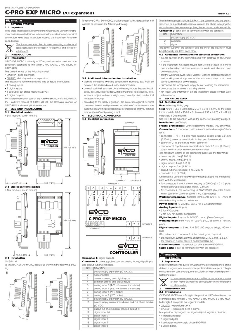
On a flat surface, with spacers (not provided); dimensions are in mm.
Recommendations for installation:
• the figure on the left refers to the user interface, the figure on he right the module
• ensure that the operating conditions (operating temperature, humidity, etc.) are within the limits indicated in
the technical data sheets
• do not install the device near to any sources of heat (heating elements, hot air conduits, etc.), equipment
containing powerful magnets (large diffusers, etc.), areas affected by direct sunlight, rain, humidity, excessive
dust, mechanical vibration or shock
• possible metal parts (or possible low voltage circuits) close to the boards must be 13 mm away at least; metal
parts must be put to earth
• in compliance with safety regulations, the device must be installed correctly, and in such a way as to protect
against any contact with electrical parts; all safety devices must be fixed so that they cannot be removed without
the use of tools.
1.3 Electrical connections
2 USER INTERFACE
2.1 Introductory information
The device has the following operational states:
• "on" (the device is switched on and an operating cycle is running)
• "stand-by" (the device is switched on and no operating cycle is
running, but it is possible to select one)
• "off" (the device is switched on and no operating cycle is running,
and it is not possible to select any).
If power is interrupted while in the "on" mode, when power is restored
the device will be in the same state and the operational cycle will be
restarted from the point reached when the power interr. occurred .
If power is interrupted while in "stand-by" or "off" mode, when power
is restored the device will be in the same state.
2.2 Switching the device on/off ("off"/"stand-by")
• ensure no procedures are running
• press B1 for 5 s
The regulators are switched off while in "off" mod.
2.3 Starting/stopping an operational cycle ("on"/
"stand-by")
•ensure no procedures are running
• press B1
The regulators are switched off while in "stand-by" mode.
2.4 The display
In the "on" state, during normal operation, display DY1 shows:
• the temperature measured by the needle probe if a set-temperature
chilling or freezing operation is ongoing
• the temperature of the cabinet if a set-temperature chilling, or timed
freezing or a storage operation is ongoing.
Display DY2 shows:
• the amount of time for a blast chill or freezing operation, if these are
ongoing
•“- - -” if a storage operation is ongoing.
Points to note in relation to electrical connections:
• do not use electric or pneumatic screw-wrenches on the terminal board
• if the device has been moved from a cold to a warm environment, condensation
may have formed inside; please wait approx. one hour prior to switching on
• ensure that the voltage, frequency and operational power of the device are
compatible with the local power supply
• disconnect the power prior to proceeding with any kind of maintenance operation
• do not use the device as a safety device
• for repairs and any information relating to the device, contact the Evco dealer
network.

Evco S.r.l. • File EVC80P16N7DSM00_EVC99T00X0XXX01_(GB)_A4_v1.00.pdf • page 2/6
While in "stand-by" mode, display DY1 shows the cabinet tempera-
ture and display DY2 shows "- - -".
While in "off" mode, display DY1 shows "OFF" and display DY2 is off.
2.5 Displaying the temperatures detected by the
probes
• ensure the device is in "off" mode and no procedures are running
• press B2 and B4 for 5 s: display DY1 will show the message "Pr1"
and display DY2 will show the cabinet temperature
• press B4 or B6 to select one of the labels shown in the table
below.
CODE MEANING
Pr1 cabinet probe
Pr2 needle probe
Pr3 evaporator probe
Pr4 condenser probe
To exit the procedure:
• press B1
If there is no condenser probe (parameter P3 = 0), label "Pr4" will not
be displayed.
2.6 Starting/stopping manual defrosting
To start defrosting in manual mode:
• ensure the device is in "off" mode and no procedures are running
• pressB11 : display DY1 will show “dEF”.
If the evaporator temperature is above the value set by parameter P23,
defrosting will not be activated.
To stop defrosting in manual mode:
• pressB11
2.7 Switching on the UV light (cabinet sterilisation)
• ensure that the device is in "stand-by" mode, that no procedures are
running and that the micro port input is not active
• pressB10
The UV light is turned on for the period of time established by parameter
P46 or until B10 is pressed once more.
2.8 Heating the needle probe
• ensure that the device is in "stand-by" mode, that no procedures are
running and that the micro port input is not active
• press B2 for 5 s: the needle probe will be heated until it reaches the
temperature set by parameter P47 or at most for the period
of time set by parameter P48.
If the temperature detected by the needle probe is above the value set
by parameter P47, heating will not be started.
The micro-port input will not be reported during needle probe heating.
2.9 Buzzer mute
• ensure no procedures are running
• press B4
After the period of time established by parameter P56 has elapsed, the
buzzer is automatically muted.
3 OPERATIONAL CYCLES
3.1 Introductory information
The device has the following operational cycles:
• hard set-temperature chilling and storage
• normal set-temperature chilling and storage
• set-temperature freezing and storage
• hard timed chilling and storage
• timed normal chilling and storage
• timed freezing and storage.
Set-temperature cycles are preceded by a test to check correct needle
probe insertion (see parameters P14 and P15); if the result of the test is
negative, cycles will be started in timed mode.
3.2 Hard set-temperature chilling and storage cycle
To select the cycle:
• ensure the device is in "off" mode and no procedures are running
• press B7 : display DY1 will show the operational setpoint and L7
will switch on.
To alter the first step operational setpoint:
• press B4 or B6
To alter the second step operational setpoint:
• press B7 for 5 s: LED L7 will flash
• press B4 or B6
These settings remain active until another cycle is selected.
Also, it is possible to set the first step operational setpoint by means of
parameter P6 and the second step operational setpoint by means of
parameter P4; the hard chill process progresses from the first step to
the second when the temperature detected by the needle probe reaches
the value set by parameter P12.
To start the cycle:
• press B1
When the temperature detected by the needle probe reaches the value
set by parameter P10, the buzzer is activated for the length of time set
by parameter P55 and the device switches to storage mode.
To interrupt the cycle:
• press B1
3.3 Normal set-temperature chilling and storage cycle
To select the cycle:
• ensure the device is in "off" mode and no procedures are running
• press B8 : display DY1 will show the operational setpoint and LED
L8 will switch on.
To alter the operational setpoint:
• press B4 or B6
These settings remain active until another cycle is selected.
It is also possible to set the operational setpoint by means of parameter
P4.
To start the cycle:
• press B1
When the temperature detected by the needle probe reaches the value
set by parameter P10, the buzzer is activated for the length of time set
by parameter P55 and the device switches to storage mode.
To interrupt the cycle:
• press B1
3.4 Set-temperature freezing and storage cycle
To select the cycle:
• ensure the device is in "off" mode and no procedures are running
• press B9 : display DY1 will show the operational setpoint and LED
L9 will switch on.
To alter the operational setpoint:
• press B4 or B6
These settings remain active until another cycle is selected.
It is also possible to set the operational setpoint by means of parameter
P5.
To start the cycle:
• press B1
When the temperature detected by the needle probe reaches the value
set by parameter P11, the buzzer is activated for the length of time set
by parameter P55 and the device switches to storage mode.
To interrupt the cycle:
• press B1
3.5 Hard timed blast chilling and storage cycle
To select the cycle:
• ensure the device is in "off" mode and no procedures are running
• press B7 : display DY1 will show the operational setpoint and LED
L7 will switch on.
To alter the first step operational setpoint:
• press B4 or B6
To alter the second step operational setpoint:
• press B7 per 5 s: LED L7 will flash
• press B4 or B6
It is also possible to set the first step operational setpoint by means of
parameter P6 and the second step operational setpoint by means of
parameter P4.
• press B3 : display DY2 will show the duration of the chilling step
and LED L3 will be switched on.
To alter the duration of the chilling step:
• press B4 or B6
It is also possible to set the chill duration time by means of parameter
P16.
These settings remain active until another cycle is selected.
The hard chill process switches from the first step to the second step
once the period of time established by parameter P18 has elapsed.
To start the cycle:
• press B1
When the chill duration time has elapsed, the buzzer is activated for the
length of time set by parameter P55 and the device switches to storage
mode.
To interrupt the cycle:
• press B1
3.6 Normal timed chilling and storage cycle
To select the cycle:
• ensure the device is in "off" mode and no procedures are running
• press B8 : display DY1 will show the operational setpoint and LED
L8 will switch on.
To alter the operational setpoint:
• press B4 or B6
It is also possible to set the operational setpoint by means of parameter
P4.
• press B3 : display DY2 will show the duration of the chilling step
and LED L3 will be switched on.
To alter the duration of the chilling step:
• press B4 or B6
It is also possible to set the chill duration time by means of parameter
P16.
These settings remain active until another cycle is selected.
To start the cycle:
• press B1
When the chill duration time has elapsed, the buzzer is activated for the
length of time set by parameter P55 and the device switches to storage
mode.
To interrupt the cycle:
• press B1
3.7 Timed freezing and storage cycle
To select the cycle:
• ensure the device is in "off" mode and no procedures are running
• press B9 : display DY1 will show the operational setpoint and LED
L9 will switch on.
To alter the operational setpoint:
• press B4 or B6
It is also possible to set the operational setpoint by means of parameter
P5.
• press B3 : display DY2 will show the duration of the freezing step
and LED L3 will be switched on.
To alter the duration of the freezing step:
• press B4 or B6
It is also possible to set the freeze duration time by means of parameter
P17.
These settings remain active until another cycle is selected.
To start the cycle:
• press B1
When the freezing step duration time has elapsed, the buzzer is activated
for the length of time set by parameter P55 and the device switches to
storage mode.
To interrupt the cycle:
• press B1
3.8 Storage, selection and starting a program
The device allows storage of operation cycle settings in programs; up
to 99 programs can be stored.
To store a program:
• proceed as described in paragraphs 3.5, 3.6 or 3.7 without starting
the cycle
• pressB12 for 5 s: display DY1 will show the label of the first unused
program
• press B4 or B6 to select another label
• pressB12 for 5 s: the device will store the program and exit from the
procedure (any programs with the same label will be
overwritten).
To select and start a stored program:
• ensure the device is in "stand-by" mode and no procedures are
running
• pressB12 : display DY1 will show the label of the first program
• press B4 or B6 to select a program
• press B1
To display the label of the current program:
• pressB12
3.9 Additional functions accessible during
operational cycles
To display the cabinet temperature during a set-temperature chilling
step or during a set-temperature freezing step:
• press the key relating to the current cycle: display DY1 displays the
cabinet temperature for 5 s.
To display the temperature detected by the needle probe during a
timed chilling step, timed freezing step or during storage:
• press B2 : display DY1 shows the temperature measured by the
needle probe for 5 s.
To display the time elapsed since starting a chilling or freezing step:
• press B4 : display DY2 shows the elapsed time for 5 s.
If the key is pressed during the storage phase, display DY2 will show
the effective duration of the chilling or freezing process
4 SETTINGS
4.1 Setting the date and time
To access the procedure:
• ensure the device is in "off" mode and no procedures are running
To alter the date and time:
• press B3 for 5 s: display DY1 will show "YY" and display DY2 will
show the last two digits corresponding to the year
• press B4 or B6 to change the year
• press B3 : display DY1 will show "NN" and display DY2 will show
the digits corresponding to the month (the month is
displayed in 12 month format)
• press B4 or B6 to change the month
• press B3 : display DY1 will show "dd" and display DY2 will show
the digits corresponding to the day (days are displayed in
31 day format)
• press B4 or B6 to change the day
• press B3 : display DY1 will show "hh" and display DY2 will show
the digits corresponding to the hour (hours are displayed
in 24 hour format)
• press B4 or B6 to change the hour
• press B3 : ildisplay DY1 will show "nn" and display DY2 will
show the digits corresponding to the minutes
• press B4 or B6 to change the minutes
• press B3 : the device will exit the procedure.
4.2 Setting the configuration parameters
To access the procedure:
• ensure the device is in "off" mode and no procedures are running
• press B4 and B6 for 5 s: display DY1 will show "PA" and display
DY2 will show the corresponding value.
To select a parameter:
• press B4 or B6
To modify a parameter:
• press B3 : LED L3 will be switched on
• press B4 or B6 within 60 s
• press B3
To exit the procedure:
• press B4 and B6 for5 s.
5 HACCP
5.1 Introductory information
The device is capable of storing up to 10 HACCP alarms, after which
the most recent alarm will overwrite the oldest.
The device can furnish the following information:
• the critical value
• the date and time at which the alarm occurred
• the alarm duration (from 1 minute to 999 minutes, " - - -" if the alarm
is ongoing).

Evco S.r.l. • File EVC80P16N7DSM00_EVC99T00X0XXX01_(GB)_A4_v1.00.pdf • page 3/6
• time of switchover to storage mode
• ora di un’eventuale interruzione del ciclo di funzionamento
• time of any operational cycle interruption.
Printing of the temperature occurs at operational cycle start, and at
intervals (see parameter P72).
6.4 Printing HACCP alarm information
The module prints the information reported in the table in section 5.2.
To print the information relating to the alarms:
• ensure the device is in "off" mode and no procedures are running
• pressB12 for 5 s: display DY1 will show "Prt"
• pressB12
To exit the procedure:
• pressB12 for 5 s.
7 MESSAGES AND INDICATIONS
7.1 Messages
LED MEANING
L1 “on”/”stand-by” LED
if on, a chilling or freezing operation is ongoing
if flashing, a storage operation is ongoing
L2 needle probe LED
if on, the temperature measured by the needle probe is
being displayed
if flashing, then the result of the test to verify correct needle
probe insertion was negative; the cycle will be started in
timed mode and the buzzer will emit 5 beeps every 10 s
L3 timed operation cycle LED
if on, a timed operation cycle will have been selected (or
is ongoing
L7 hard chill LED
if on:
• a hard chill operation will have been selected
• the first step of a hard chill operation is ongoing
• modification of the hard chill first step operational setpoint
is underway
if flashing:
• modification of the hard chill second step operational
setpoint is underway
• the second step of a hard chill operation is in progress
L8 normal chilling LED
if on, a normal chill operation has been selected (or is
ongoing
L9 freezing LED
if on, a freezing operation has been selected (or is ongoing)
L10 UV light (cabinet sterilisation) LED
if on, the UV light is on (a cabinet sterilisation operation is
ongoing)
L11 defrosting LED
if on, defrosting is ongoing
L12 program LED
if on, program storing, selection or execution is ongoing
L13 HACCP LED
if on, program storing, selection or execution is ongoing
7.2 Indications
CODE MEANING
dEF if on, defrosting is ongoing
if flashing, drip-draining is ongoing
8 ALARMS
8.1 Alarms
CODE MEANING
AL Minimum cabinet temperature alarm
Remedies:
• check the cabinet temperature
• see parameters P64 and P66
Consequences:
• the alarm output will be activated
AH Maximum cabinet temperature alarm
Remedies:
• check the cabinet temperature
• see parameters P65 and P67
Consequences:
• the alarm output will be activated
Ht Condenser temperature alarm
Remedies:
• check the condenser temperature
• see parameter P62
Consequences:
• the operational cycle will be interrupted
• it will not be possible to start any operational cycles
• the condenser fan will be switched on
• the alarm output will be activated
d - r Micro-port input alarm
Remedies:
• check the causes of the input activation
• see parameter P38
Consequences if the alarm occurs while in "on" mode:
• the compressor will be shut down
• if parameter P37 is set to 1, the evaporator fan will be
switched off
• if parameter P59 is set to 0, the cabinet light will be
switched on
• the condenser fan will be switched off
• if the UV light is on (i.e. if cabinet sterilisation is ongoing),
the UV light will be switched off
CODE ALARM TYPE (AND CRITICAL VALUE)
Er0 cabinet probe error (the temperature of the cabinet when
the alarm condition occurred)
Er1 evaporator probe alarm (the maximum cabinet temperature
during the alarm condition)
Er3 needle probe alarm (the maximum cabinet temperature
during the alarm condition)
Er4 condenser probe alarm (the maximum cabinet
temperature during the alarm condition)
AL (minimum) cabinet temperature alarm (the minimum cabi-
net temperature during the alarm condition)
AH (maximum) cabinet temperature alarm (the maximum
cabinet temperature during the alarm condition)
Ht condenser temperature alarm (the maximum cabinet
temperature during the alarm condition)
d - r micro port input alarm (the maximum cabinet temperature
during the alarm condition)
HP high pressure input alarm (the maximum cabinet
temperature during the alarm condition)
LP low pressure input alarm (the maximum cabinet
temperature during the alarm condition)
HA compressor thermal protection input alarm (the maximum
cabinet temperature during the alarm condition)
PF power failure alarm (the cabinet temperature on restoration
of power)
5.2 Viewing HACCP alarm information
Viewing HACCP alarm information:
• ensure the device is in "off" mode and no procedures are running
• pressB12 for 5 s: display DY1 will show "Prt".
To select an alarm:
• press B4 or B6 display DY1 will show the number of the alarm
(for example "n03") and display DY2 will show the
relevant code (for example "AH", or one of the codes
reported in the table in section 5.1; the lower the number,
the older the alarm itself).
To display the information relating to the alarm:
• press B3 repeatedly: the display will show the following information
in sequence (for example):
INFO MEANING
St on display DY1
y07 on display DY2
The alarm occurred in 2007 (continued ...)
M03 on display DY1
d26 on display DY2
The alarm occurred on 26 March 2007
h16 on display DY1
d30 on display DY2
The alarm occurred at 4:30pm
ton display DY1
8on display DY2
The critical value is 8 °C/8 °F
dur on display DY1
75 on display DY2
The alarm has lasted for 75 minutes
n03 on display DY1
AH on display DY2
The selected alarm
LED L13 provides information relating to the status of the HACCP
alarm memory; please refer to section 7.1.
To exit the information series:
• press B4 or B6 display DY1 will show the number of another
alarm and display DY2 will show the corresponding
code.
To exit the procedure:
• pressB12 for 5 s.
5.3 Deleting the HACCP alarm list
• set parameter P73 to 1.
6 DATA PRINTING
6.1 Introductory information
The device has a serial port for communicating with the PM 100A
X9S001 print module.
6.2 Connecting the PM 100A X9S001 print module
Connecting the PM 100A X9S001 print module:
• ensure that parameter P71 is set to 1
• ensure that the print module baud rate is set to 9,600 baud
• ensure that the module parity is set to odd.
6.3 Printing operational cycle information
Printing operational cycle information:
• operational cycle start date
• operational cycle or program type (or one of the codes listed in the
table below)
CODE MEANING
T>>>* hard set-temperature chilling and storage
T* normal set-temperature chilling and storage
T*** set-temperature freezing and storage
t>>>* hard timed chilling and storage
t* timed normal chilling and storage
t*** timed freezing and storage
P01...99 program 01 ... 99
• printing time
• cabinet temperature (Pr1)
•temperature measured by the needle probe (Pr2, only if the
operational cycle is a set-temperature cycle)
• the alarm output will be activated
Consequences if the alarm occurs while in "stand-by" mode:
• if parameter P59 is set to 0, the cabinet light will be
switched on
HP High pressure input alarm
Remedies:
• check the causes of the input activation
• see parameter P40
Consequences:
• the operational cycle will be interrupted
• the loads will be switched off
• it will not be possible to start any operational cycles
• the alarm output will be activated
LP Low pressure input alarm
Remedies:
• check the causes of the input activation
• see parameter P42
Consequences:
• the operational cycle will be interrupted
• the loads will be switched off
• it will not be possible to start any operational cycles
• the alarm output will be activated
HA Compressor thermal protection input alarm
Remedies:
• check the causes of the input activation
• see parameter P44
Consequences:
• the operational cycle will be interrupted
• the loads will be switched off
• it will not be possible to start any operational cycles
• the alarm output will be activated
rES Power failure during an operational cycle
Remedies:
• check the causes of the input activation
Consequences:
• the operational cycle will be restored from the point
where the power failure occurred
When the cause that triggered the alarm has been resolved, the device
restores normal operation.
9 INTERNAL DIAGNOSTICS
9.1 Internal diagnostics
CODE MEANING
Er0 Cabinet probe error
Remedies:
• see parameter P60
• check probe integrity
• check probe-device connection
• check the cabinet temperature
Consequences:
• the operational cycle will be interrupted
• the loads will be switched off
• it will not be possible to start any operational cycles
• the alarm output will be activated
Er1 Evaporator probe error
Remedies:
• the same as for the previous case, but in relation to the
evaporator probe
Consequences:
• defrosting will last for the length of time set by parameter
P24
• the evaporator fan will be switched off during storage
• the alarm output will be activated
Er3 Needle probe error
Remedies:
• the same as for the previous case, but in relation to the
needle probe
Consequences:
•if a set-temperature chilling or freezing operation is
ongoing, the operational cycle will be interrupted
•it will not be possible to start any set-temperature
operational cycles
• the alarm output will be activated
Er4 Condenser probe error
Remedies:
• the same as for the previous case, but in relation to the
condenser probe
Consequences:
•the condenser fan will operate in parallel with the
compressor, except when set by parameter P54
• the alarm output will be activated
Err User interface-module communication error
Remedies:
• check the user interface-module connection
Consequences:
• if an operational cycle is ongoing, the device will continue
to function normally
• it will not be possible to start any operational cycles
When the cause that triggered the alarm has been resolved, the device
restores normal operation.

Evco S.r.l. • File EVC80P16N7DSM00_EVC99T00X0XXX01_(GB)_A4_v1.00.pdf • page 4/6
11 CONFIGURATION PARAMETERS
11.1 Configuration parameters
PARAM. MIN. MAX. U.o.M. DEF.
P001--- 1
P1 -10 10 °C/°F (2) 0
P2 -10 10 °C/°F (2) 0
P3 -10 10 °C/°F (2) 0
PARAM. MIN. MAX. U.o.M. DEF.
P4 -40 99 °C/°F (2) -2
P5 -40 99 °C/°F (2) -40
P6 -40 P4 °C/°F (2) -20
P7 -40 99 °C/°F (2) 3
P8 -40 99 °C/°F (2) -20
P9 1 15 °C/°F (2) 2
P10 -40 99 °C/°F (2) 3
P11 -40 99 °C/°F (2) -18
P12 -40 P10 °C/°F (2) 1 5
P13 -40 99 °C/°F (2) 6 5
P14 0 99 °C/°F (2) 0
P15 1 99 s 60
P16 1 400 min 90
P17 1 400 min 240
P18 1 P16 min 20
PARAM. MIN. MAX. U.o.M. DEF.
P19 0 99 min 0
P20 0 99 min 0
P21 0 99 min 0
PARAM. MIN. MAX. U.o.M. DEF.
P22 0 2 - - - 1
P23 -40 99 °C/°F (2) 8
P24 1 99 min/s (6) 20
P25 0 9 9 h/min (6) 8
P26 0 99 min/s (6) 1
P27 0 1 - - - 0
P28 0 99 min/s (6) 2
P29 0 1 - - - 0
P30 0 400 s 30
SENSOR INPUTS
unit of temperature measurement (1)
0=°F
1=°C
cabinet probe offset
evaporator probe offset
needle probe offset
MAIN CONTROLLER
operational setpoint during the second hard chill step; also, operational setpoint during normal chilling (with reference to the cabinet probe)
operational setpoint during freezing (with reference to the cabinet probe)
operational setpoint during the first hard chill step (with reference to the cabinet probe)
operational setpoint during post-chill storage (with reference to the cabinet probe)
operational setpoint during post-freeze storage (with reference to the cabinet probe)
P4, P5, P6, P7 and P8 differential
set temperature chill end temperature (with reference to the needle probe)
set temperature freeze end temperature (with reference to the needle probe)
temperature at which the hard chill switches from the first step to the second (with reference to the needle probe)
temperature above which it is not possible to start a set-temperature operational cycle (with reference to the needle probe)
needle probe and the cabinet temperature for verification of correct needle probe insertion (3)
0 = the test will not be performed
duration of the second test to check correct needle probe insertion; see also P14 (4)
maximum set temperature chill duration; also timed chill duration
maximum set temperature freeze duration; also timed freeze duration
first hard timed chill step duration
COMPRESSOR PROTECTIONS
compressor delay from device power on (from restoration of power)
minimum elapsed time period between two consecutive compressor start-up operations
minimum compressor shut-down time
DEFROSTING
defrost type (5)
0 = electric (defrost on relay)
1 = hot gas (defrost compressor and relay on)
2 = air (evaporator fan on)
defrost end temperature (with reference to the evaporator probe)
maximum defrost duration
defrost interval during storage; see also P26
0 = intermittent defrosting will never be activated (only the first will be activated)
first defrost delay from start of storage; see also P25
defrosting at start of chilling and freezing
1 = YES
drip-drain duration
resetting of compressor protections at start of defrosting (only if P22 = 1)
1 = YES
elapsed time between the defrost request and switching on the compressor (only if P22 = 1 and providing that the compressor is off when the defrost is requested); see also
P31 (7) (8)
PT • 03/08
10 TECHNICAL INFORMATION
10.1 Technical information
Case: open case.
Front panel protection classification: IP 00.
EVC99T00X0XXX01 (user interface) connections: plug-in
terminal board (to the module); the user interface is connected to the
module by means of a 4-core cable (the cable is not included with the
device).
EVC80P16N7DSM00 (module) connections: plug-in terminal
board (power supply, inputs, outputs and communication ports).
Operating temperature: from 0 to 55ºC (10 ... 90% relative humidity,
without condensation).
EVC99T00X0XXX01 (user interface) power supply: The user
interface is powered from the module.
EVC80P16N7DSM00 (module) power supply: 230 V AC, 50/60
Hz, 10 VA (nominal).
Maintaining the time and date in the absence of power: 2
years.
Alarm buzzer: present.
Sensor inputs: 4 (cabinet probe, evaporator probe, needle probe
and condenser probe) for PTC/NTC probes.
Digital inputs: 4 (micro port, high pressure, low pressure and
compressor thermal protection) for NA/NC (clean contact) contacts.
Sensor range: from -50 to 99ºC (from -50 to 210ºF) for PTC probes,
from -40 to 99ºC (from -40 to 210ºF) for NTC probes.
Sensitivity: 1ºC/1ºF.
Digital outputs: 10 relays:
•compressor realy: 8 A res. @ 250 VAC (NA
contacts)
•down pump electrovalve relay: 8 A res. @
250 VAC (NA contacts)
•evaporator fan relay: 8 A res. @ 250 VAC (NA
contacts)
•defrost relay: 8 A res. @ 250 VAC (NA contacts)
•UV light relay: 8 A res. @ 250 VAC (NA contacts)
•needle probe heater relay: 8 A res. @ 250
VAC (NA contacts)
•condenser fan relay: 8 A res. @ 250 VAC (NA
contacts)
•door element relay: 8 A res. @ 250 VAC (NA
contacts)
•cabinet light relay: 8 A res. @ 250 VAC (NA
contacts)
•alarm relay: 8 A res. @ 250 VAC (NA contacts).
The maximum current allowed on the loads is 8 A.
Communication ports: two RS-485 ports (on the module), for:
• the communication with the user in-
terface
• the communication with the printing
module PM 100A X9S001.
The maximum length of the connecting cables is 50 m.

Evco S.r.l. • File EVC80P16N7DSM00_EVC99T00X0XXX01_(GB)_A4_v1.00.pdf • page 5/6
P31 0 400 s 60
PARAM. MIN. MAX. U.o.M. DEF.
P32 -40 99 °C/°F (2) -1
P33 -15 15 °C/°F (2) 1
P34 0 1 - - - 1
P35 0 15 min/s (6) 3
P36 -40 99 °C/°F (2) 9 0
P37 0 1 - - - 1
PARAM. MIN. MAX. U.o.M. DEF.
P38 0 1 - - - 1
P39 0 200 min 30
P40 0 1 - - - 1
P41 0 200 s 120
P42 0 1 - - - 0
P43 0 200 s 0
P44 0 1 - - - 0
P45 0 200 s 0
PARAM. MIN. MAX. U.o.M. DEF.
P46 0 99 min 5
PARAM. MIN. MAX. U.o.M. DEF.
P47 -40 99 °C/°F (2) 4 5
P48 0 99 s 15
PARAM. MIN. MAX. U.o.M. DEF.
P49 -20 20 °C/°F (2) 5
P50 -10 10 °C/°F (2) 2
PARAM. MIN. MAX. U.o.M. DEF.
P51 0 1 - - - 1
P52 -45 100 °C/°F (2) 2 0
P53 -10 10 °C/°F (2) 5
P54 0 300 s 30
PARAM. MIN. MAX. U.o.M. DEF.
P55 0 99 s 3
P56 1 400 s 15
P57 0 999 s 10
P58 0 1 - - - 0
P59 - - - - - - - - - - - -
P60 0 1 - - - 0
P61 0 1 - - - 0
PARAM. MIN. MAX. U.o.M. DEF.
P62 0 99 °C/°F (2) 7 0
P63 0 30 °C/°F (2) 1 0
PARAM. MIN. MAX. U.M. DEF.
P64 -99 0 °C/°F (2) 0
P65 0 99 °C/°F (2) 0
P66 -99 0 °C/°F (2) 0
P67 0 99 °C/°F (2) 0
P68 1 15 °C/°F (2) 2
P69 0 255 min 0
P70 0 255 min 0
PARAM. MIN. MAX. U.o.M. DEF.
P71 0 1 - - - 0
P72 0 60 min 5
P73 0 1 - - - 0
P74 - - - - - - - - - - - -
P75 - - - - - - - - - - - -
P76 - - - - - - - - - - - -
(1) Altering parameter P0 effects all parameters where the unit of measurement is degrees Celsius or degrees Fahrenheit
(2) the unit of measurement depends on parameter P0
(3) (3)the test result is positive if the difference between the temperature measured by the needle probe and the cabinet temperature is greater than the value set by parameter P14 at least 3 times out of 5 (checking
is every 10 s); if the test result is negative a second test is initiated (se parameter P15)
(4) the result of the second test is positive if the difference between the temperature measured by the needle probe and the cabinet temperature increases by at least 1C/1F with respect to the previous check at
least 6 times out of 8 (checking occurs every P15/8 s); if parameter P15 is set to a value of less than 5 s, the second test will not be executed
(5) if parameter P22 is set to 2, micro port input activation will not be signalled
(6) the unit of measurement depends on parameter P58
(7) defrosting will be activated on conclusion of the time which is greatest between those set by parameters P30 and P31
elapsed time between the defrost request and activation of the solenoid valve (only if P22 = 1 and on condition that the compressor is off when defrosting is requested); see
also P30 (7) (8)
EVAPORATOR FAN
temperature above which the evaporator fan is switched off during storage (with reference to the evaporator probe)
P32 differential
evaporator fan activity during defrosting (only if P22 = 0 or 1)
0=on
1 = off
evaporator fan activity during defrosting (only if P22 = 0 or 1
temperature above which the evaporator fan is switched off (with reference to the cabinet probe)
effect caused by activation of microport input on evaporator fan
0 = no effect
1 = the evaporator fan will be switched off
DIGITAL INPUTS
microport input contact type
0 = NA (input active with contact closed)
1 = NC (input active with contact open)
micro port input alarm delay (9)
high pressure input alarm delay
0 = NA (input active with contact closed)
1 = NC (input active with contact open)
high pressure input alarm delay
low pressure input contact type
0 = NA (input active with contact closed)
1 = NC (input active with contact open)
low pressure input alarm delay
compressor thermal protection input contact type
0 = NA (input active with contact closed)
1 = NC (input active with contact open)
compressor thermal protection input alarm delay
CABINET STERILISATION
UV light on duration (duration of cabinet sterilisation)
NEEDLE PROBE HEATING
needle probe heating end temperature (with reference to the needle probe)
maximum duration of needle probe heating
DOOR ELEMENTS
the temperature, below which the door elements are switched on (with reference to the cabinet probe)
P49 differential
CONDENSER FAN
condenser fan activity in the absence of the condenser probe (P61 = 0)
0 = in parallel with compressor
1=on
the temperature below which the condenser fan is switched off in the presence of the condenser probe (P61 = 1) and on condition that the compressor is on (with reference
to the condenser probe); see also P54
P52 differential
condenser fan switch off delay on switching off the compressor in the presence of the condenser probe (P61 = 1); see also P52
MISCELLANEOUS
chill and freeze cycle completion buzzer duration
maximum buzzer duration during an alarm state
elapsed time between switching on the compressor and down pump valve activation (down pump in power up); also elapsed time between deactivation of the down pump
valve and switching off the compressor (down pump in power down)
defrost parameter units of measurement
0 = P25 h, P24, P26, P28 and P35 min
1 = P25 min, P24, P26, P28 and P35 s
reserved
probe type
0 = NTC
1 = PTC
condenser probe enabling
1 = YES
CONDENSER TEMPERATURE ALARMS
the temperature above which the condenser temperature alarm is activated (with reference to the condenser probe)
P62 differential
CABINET TEMPERATURE ALARMS
temperature below which the minimum temperature alarm is activated during post-chill storage, with relation to P7, i.e. "P7 + P64" (with reference to the cabinet probe)
0 = no alarm
temperature above which the maximum temperature alarm is activated during post-chill storage, with relation to P7, i.e. "P7 + P65" (with reference to the cabinet probe)
0 = no alarm
temperature below which the minimum temperature alarm is activated during post-freezing storage, with relation to P8, i.e. "P8 + P66" (with reference to the cabinet probe)
0 = no alarm
temperature above which the maximum temperature alarm is activated during post-freezing storage, with relation to P8, i.e. "P8 + P67" (with reference to the cabinet probe)
0 = no alarm
P64, P65, P66 and P67 differential
storage operation start-up temperature alarm delay
temperature alarm delay
DATA PRINTING
enable printing
1 = YES
print interval
HACCP alarm list deletion
1 = YES (10)
reserved
reserved
reserved

EVCO S.r.l. This document belongs to Evco; unless you are authorized by Evco, you can not publish this document.
Via Mezzaterra 6, 32036 Sedico Belluno ITALY Evco does not take any responsibility about features, technical data and possible mistakes related in this document.
Phone +39-0437-852468 • Fax +39-0437-83648 Evco does not take any responsibility about damages coming by the non-observance of additional information.
[email protected] • www.evco.it Evco reserves the right to make any change without prior notice and at any time without prejudice the basic safety and operating features.
Evco S.r.l. • File EVC80P16N7DSM00_EVC99T00X0XXX01_(GB)_A4_v1.00.pdf • page 6/6
(8) if defrosting is requested when the compressor is on and the time set by parameter P30 is less than the value set by parameter P31, the compressor will remain on and the solenoid valve and defrosting will be
activated after the time "P31 - P30" has elapsed since the defrost request; vice versa, if defrosting is requested when the compressor is on and the time set by parameter P30 is greater than that set by parameter
P31, when defrosting is requested the compressor will be switched off for the greater of the times between those set by parameters P19, P20 and P21 after which the compressor and defrosting will be activated
(the solenoid valve will be activated "P30 - P31" s prior to activation of defrosting)
(9) parameter P39 has no effect during UV light switch on (cabinet sterilisation)
(10) altering parameter P73 is effective on exiting the configuration parameter setting procedure; as soon as you will quit the configuration parameters setting procedure, parameter P73 will automatically get
value 0.
This manual suits for next models
1
Table of contents
Other Evco Control System manuals
Popular Control System manuals by other brands

Toshiba
Toshiba TOSDIC-CIE DS Operation manual

Modine Manufacturing
Modine Manufacturing 5H104766 quick start guide

ABB
ABB Ability 800xA Series Operations

elsner elektronik
elsner elektronik WS1000 Style First steps

Lippert Components
Lippert Components OneControl HVAC Control 2.0 owner's manual

CYP
CYP CDPS-RLY Operation manual