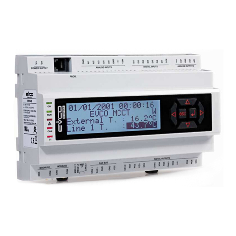
Evco C-PRO 3 CLIMA sistema+ User guide

Evco S.p.A. c-pro 3 CLIMA sistema | Installer manual ver.1.1 | Code 144CP3CSE114
page 1 of 74
C-PRO 3 CLIMA sistema+
Climatic modules for the air conditioning
and heating of buildings
ENGLISH
INSTALLER MANUAL er. 1.1
CODICE 144CP3CSE114

Evco S.p.A. c-pro 3 CLIMA sistema | Installer manual ver.1.1 | Code 144CP3CSE114
page 2 of 74
Important
Important
Read t is document t oroug ly before installation and before use of t e device and follow all recommendations; keep
t is document wit t e device for future consultation.
T e following symbols support reading of t e document:
indicates a suggestion
indicates a warning.
T e device must be disposed of in compliance wit local Standards regarding t e collection of electric and electronic
equipment.

Evco S.p.A. c-pro 3 CLIMA sistema | Installer manual ver.1.1 | Code 144CP3CSE114
page 3 of 74
Index
1
GENERALITIES ........................................................................................................................................ 6
1.1
Description..................................................................................................................................... 6
2
APPLICATIONS ........................................................................................................................................ 7
3
INSTALLATION ........................................................................................................................................ 8
3.1
Dimensions .................................................................................................................................... 8
3.1.1
T ermal power plant (MCCT), zone modules (MCZN) and solar panels (MCPS) dimensional drawing. ..... 8
3.1.2
Grap ical display dimensional drawing (Vroom). ............................................................................. 8
3.2
Assembly ....................................................................................................................................... 9
3.2.1
Assembly of t ermal power plant modules (MCCT), Zone (MCZN) and solar panels (MCPS) .................. 9
3.2.2
Display Assembly (Vroom) ......................................................................................................... 10
3.3
Electric connections ....................................................................................................................... 11
3.3.1
T ermal power plant electric connections (MCCT) hecto + ............................................................. 11
3.3.2
Zones electric connections (MCZN). ............................................................................................ 13
3.3.3
Return temperature control ............................................................................................................. 14
3.3.4
Ric iesta C iller/pompa di calore ................................................................................................ 14
3.3.5
Configuration Options ................................................................................................................... 14
3.3.6
Solar panels electric connections (MCPS). .................................................................................... 15
3.4
Regulators network configuration .................................................................................................... 16
3.4.1
MCCT t ermal power plant controller network configuration ........................................................... 17
3.4.2
Network Configuration zone modules MCZN ................................................................................. 17
3.4.3
MCPS solar panels controller network configuration ....................................................................... 17
3.5
Displays network configuration ....................................................................................................... 17
3.5.1
Public terminal ......................................................................................................................... 18
3.5.2
Module private terminal ............................................................................................................. 19
3.5.3
Zone private terminal ................................................................................................................ 20
4
USER INTERFACE .................................................................................................................................. 21
4.1
Display and keyboard .................................................................................................................... 21
4.1.1
Built-in interface ....................................................................................................................... 21
4.2
Navigation t roug t e applications making up t e system ................................................................ 22
4.2.1
Access a c-pro 3 ecto+ MCZN zone regulator .............................................................................. 22
4.2.2
Access t e regulator for c-pro 3 hecto MCPS solar panels .............................................................. 22
5
c-pro 3 hecto+ MCCT regulator ............................................................................................................... 23
5.1
List of pages ................................................................................................................................ 23
5.2
Menu ........................................................................................................................................... 23
5.2.1
Home page: ............................................................................................................................. 23
5.2.2
Status page ............................................................................................................................. 24
5.2.3
Menu page ............................................................................................................................... 25
5.2.4
Network .................................................................................................................................. 25
5.2.5
Maintenance menu .................................................................................................................... 26
5.2.6
Installer menu .......................................................................................................................... 26
5.2.7
Manufactor menu ...................................................................................................................... 26
5.3
Alarms/log menu .......................................................................................................................... 27
5.3.1
Alarms log ............................................................................................................................... 27
5.3.2
Reset active alarms ................................................................................................................... 27
5.3.3
Reset alarms log ....................................................................................................................... 27
5.3.4
Table of alarms ........................................................................................................................ 27
5.4
Clock menu .................................................................................................................................. 30

Evco S.p.A. c-pro 3 CLIMA sistema | Installer manual ver.1.1 | Code 144CP3CSE114
page 4 of 74
5.5
User menu ................................................................................................................................... 30
5.6
Maintenance menu ........................................................................................................................ 30
5.7
Installer menu .............................................................................................................................. 30
5.8
Manufactor menu .......................................................................................................................... 30
5.9
Main OFF page.............................................................................................................................. 31
5.10
Main ON page ............................................................................................................................... 31
5.11
State pages .................................................................................................................................. 31
5.11.1
State page supply lines L1 to L6 ............................................................................................. 31
5.11.2
State page and access to t e MCPS solar panels module ........................................................... 31
5.11.3
State and access page of t e MCZN zone regulators modules ..................................................... 31
5.12
Configuration parameters .............................................................................................................. 32
5.12.1
List of configuration parameters ............................................................................................. 32
5.13
State of t e unit ........................................................................................................................... 36
5.13.1
OFF state due to alarm .......................................................................................................... 37
5.14
Summer/winter functioning mode ................................................................................................... 37
6
c-pro 3 ecto MCZN regulator ................................................................................................................. 39
6.1
List of pages ................................................................................................................................ 39
6.2
Menu ........................................................................................................................................... 39
6.2.1
Main Screen area ...................................................................................................................... 39
6.2.2
Configuration screen area .......................................................................................................... 39
6.2.3
Screens ot setpoint area ........................................................................................................... 40
6.2.4
Screen time zones .................................................................................................................... 40
6.2.5
Screens ot oliday ................................................................................................................... 41
6.3
Main menu accessible by MCCT ....................................................................................................... 41
6.3.1
Alarm menu ............................................................................................................................. 41
6.3.2
Maintainer menu....................................................................................................................... 41
6.3.3
Installer menu .......................................................................................................................... 41
6.3.4
Manufactor menu ...................................................................................................................... 42
6.4
Pages On/Off ................................................................................................................................ 42
6.5
Configuration Parameters............................................................................................................... 42
6.5.1
List of configuration parameters ................................................................................................. 42
6.6
Unit status ................................................................................................................................... 48
6.7
Zones status ................................................................................................................................ 48
7
c-pro 3 hecto MCPS regulator ................................................................................................................. 49
7.1
List of pages ................................................................................................................................ 49
7.2
Main page .................................................................................................................................... 50
7.3
State pages .................................................................................................................................. 50
7.3.1
Functioning state of DHW circuit (boiler) ...................................................................................... 50
7.3.2
Functioning state of solar panels circuit 1 and 2 ............................................................................ 50
7.3.3
Functioning state of auxiliary circuit ............................................................................................ 50
7.4
Main menu ................................................................................................................................... 51
7.4.1
Alarms/log menu ...................................................................................................................... 51
7.4.2
Alarms log ............................................................................................................................... 51
7.4.3
Reset active alarms ................................................................................................................... 51
7.4.4
Reset alarms log ....................................................................................................................... 51
7.4.5
Set-point menu ........................................................................................................................ 51
7.4.6
Maintenance menu .................................................................................................................... 51
7.4.7
Installer menu .......................................................................................................................... 52
7.5
System Network page ................................................................................................................... 53

Evco S.p.A. c-pro 3 CLIMA sistema | Installer manual ver.1.1 | Code 144CP3CSE114
page 5 of 74
7.6
Configuration parameters .............................................................................................................. 53
7.6.1
List of MAINTENANCE menu configuration parameters ................................................................... 53
30 ............................................................................................................................................................... 55
7.6.2
List of INSTALLER menu configuration parameters ........................................................................ 56
7.7
Unit status ................................................................................................................................... 57
8
Regulations .......................................................................................................................................... 57
8.1
Regulation of t e zone temperature (MCZN, MCCT modules) .............................................................. 57
8.1.1
Regulation principle .................................................................................................................. 57
8.1.2
Management of t e zone eating/cooling manifolds (MCZN module) ............................................... 58
8.1.3
Fan Coil ................................................................................................................................... 58
8.1.4
Zone work set-point (MCZN module) ........................................................................................... 59
8.1.5
Zone anti-freeze protection (MCZN module) ................................................................................. 60
8.1.6
"Heating/cooling integration" function (MCZN modules) ................................................................. 61
8.2
Regulation of t e delivery temperature (MCCT modules) .................................................................... 61
8.2.1
Management of t e delivery circulation pumps (MCCT module) ...................................................... 61
8.2.2
Management of t e utilities set-up for eating delivery water: boiler (and eat pump (MCCT module) . 61
8.2.3
Management of t e utility set-up for cooling delivery water: t e c iller (MCCT module) ..................... 62
8.2.4
Delivery work set-point (MCCT module) ....................................................................................... 62
8.2.5
Output of t e delivery mixing valve (MCCT module) ...................................................................... 62
8.2.6
Mixing valve delivery work set-point (MCCT module) ..................................................................... 63
8.2.7
Dew point control (MCCT, MCZN modules) ................................................................................... 63
8.2.8
Control of t e ig and low delivery temperature (MCCT module) ................................................... 64
8.3
Regulation of t e zone umidity (MCZN, MCCT modules) ................................................................... 64
8.3.1
Regulation principle .................................................................................................................. 64
8.3.2
Management of t e de umidification manifold/valve (MCZN module) .............................................. 64
8.3.3
Zone umidity work set-point (MCZN module) .............................................................................. 64
8.3.4
Management of digital on/off de umidifier ................................................................................... 65
8.4
Regulation of t e DHW tank temperature for t e DHW water (MCPS module) ....................................... 65
8.4.1
Regulation principle .................................................................................................................. 65
8.4.2
Management of t e DHW circuit circulation pump (MCPS module) ................................................... 65
8.4.3
DHW tank work set-point (MCPS module) Wit DHW setpoint mode ................................................ 66
8.4.4
Management of t e AUX1 auxiliary circuit circulation pump (MCPS module) .................................... 66
8.4.5
Control of t e ig and low temperature of t e auxiliary circuit AUX1 (MCPS module) ....................... 67
8.4.6
Management and setting of t e periodic antilegionella cycle for t e DHW tank (MCPS module) ........... 67
8.5
Management and configuration of t e eating solar panel circuits (MCPS module) ................................ 68
8.5.1
Wit DHW setpoint.................................................................................................................... 68
8.5.2
con tipo setpoint pannelli ........................................................................................................... 68
8.5.3
Management of t e solar panels circuits circulation (MCPS module) ................................................ 69
8.5.4
Control of t e ig and low temperature of t e solar panel circuits (MCPS module) ........................... 69
8.5.5
Management and setting t e stagnation emergency for solar panels circuits (MCPS module) .............. 69
8.6
Ot er regulations .......................................................................................................................... 71
8.6.1
Management and setting of t e periodic anti-grip cycle (MCCT, MCPS modules) ............................... 71
8.6.2
Management of t e circulation pumps protection digital input (MCCT, MCPS modules) ....................... 71
8.6.3
Manual functioning mode (MCCT, MCZN, MCPS modules) ............................................................... 72

Evco S.p.A. c-pro 3 CLIMA sistema | Installer manual ver.1.1 | Code 144CP3CSE114
page 6 of 74
1GENERALITIES
1.1 Description
T e climatic modules of t e c-pro 3 CLIMA sistema series are devices studied for t e air conditioning and t e eating
of buildings.
T ey make use of t e programmable controllers belonging to t e c-pro 3 series and of t e user interfaces belonging
to t e same series.
T ey are available in built-in and in blind version wit remote user interface (according to t e kind of module).
T ey can be powered bot in alternating and in direct current (24 VAC/20... 40 VDC).
T e modules allow realizing an expandable and modular control device network distributed in t e main rooms of t e
building reducing t e wiring work to a minimum: t e modules c-pro 3 hecto MCCT can manage t e t ermal power
plant, t e c-pro 3 hecto MCZN ones t e air conditioning and t e eating of two zones instead and t e c-pro 3 hecto
MCPS ones finally t e t ermal solar panels.
T e central module t ermal MCCT is indispensable for t e functioning of t e system, it can be connected from one to
eig t zones MCZN control modules, eac of w ic can andle up to a maximum of six zones.
In total, t anks to t is system can be operated up to a maximum of 48 zones in temperature and umidity.
T e user interfaces can easily be integrated in residential and commercial rooms (at t e front of t e interfaces it is
possible to apply t e plates CPVP or t e plates belonging to t e series “Living” and to t e series “Lig t” Bticino).
All t e modules ave communication ports (programming, CAN, RS-485, wit MODBUS communication protocol, etc.).
T roug t e programming port it is possible to make t e upload and t e download of t e configuration parameters
(using t e programming key EVKEY10); t roug t e RS-485 one, wit MODBUS communication protocol, it is possible
to connect t e devices to t e set-up software system Parameters Manager or to t e plants monitoring and supervision
one RICS (t roug a serial interface) instead.
T roug t e CAN communication port it is possible to connect t e devices among t em.

Evco S.p.A. c-pro 3 CLIMA sistema | Installer manual ver.1.1 | Code 144CP3CSE114
page 7 of 74
2APPLICATIONS
Example of maximum configuration
- n. 1 t ermal power plant module c-pro 3 mega MCCT or c-pro 3 ecto
- n. 8 zone modules c-pro 3 ecto MCZN
- n. 1 t ermal solar panels c-pro 3 ecto MCPS
- n. 1 remote user interface for eac zone
Up to n. 48 zones (wit temperature control only) or n. 24 zones (bot wit temperature and umidity control)

Evco S.p.A. c-pro 3 CLIMA sistema | Installer manual ver.1.1 | Code 144CP3CSE114
page 8 of 74
3INSTALLATION
Below we will s ow t e dimensions, assembly and electric connections of t e c-pro 3 CLIMA sistema, made up from
t ermal power plant modules (MCCT), Zones (MCZN), solar panels (MCPS) and grap ical displays (Vroom).
3.1 Dimensions
3.1.1 Thermal power plant (MCCT), zone modules (MCZN) and solar
panels (MCPS) dimensional drawing.
3.1.2 Graphical display dimensional drawing (Vroom).

Evco S.p.A. c-pro 3 CLIMA sistema | Installer manual ver.1.1 | Code 144CP3CSE114
page 9 of 74
3.2 Assembly
3.2.1 Assembly of thermal power plant modules (MCCT), Zone (MCZN)
and solar panels (MCPS)
To install t e t ermal power plant, zone and solar panels module, operate as indicated in t e diagrams (points 1 and
2).
To remove t ermal power plant, zone and solar panels module, use a screwdriver and operate as indicated in t e
diagrams (points 3 and 4).

Evco S.p.A. c-pro 3 CLIMA sistema | Installer manual ver.1.1 | Code 144CP3CSE114
page 10 of 74
3.2.2 Display Assembly (Vroom)
T ere are t ree possibilities for assembly of t e Vroom grap ical display:
3.2.2.1 Wall recessed in 506E box
3.2.2.2 Wall-installation, on E co CPVW00 support
3.2.2.3 Panel installation

Evco S.p.A. c-pro 3 CLIMA sistema | Installer manual ver.1.1 | Code 144CP3CSE114
page 11 of 74
3.3 Electric connections
3.3.1 Thermal power plant electric connections (MCCT) hecto +
c-pro 3 hecto+ Thermal plant controller
I/O Description
1 or 2 delivery lines (PL01 = 1 or 2) 3 or more delivery lines (PL01 = from 3 to 6)
Analog inputs (NTC / 0-5V / 4-20mA)
A/I 1 CT External air temperature – NTC External air temperature – NTC
A/I 2 CT Delivery temperature 1 – NTC Delivery temperature 1 – NTC
A/I 3 CT Delivery temperature 2 – NTC Delivery temperature 2 – NTC
A/I 4 CT Summer/Winter Summer/Winter
A/I 5 EXP Not used Delivery temperature 3 – NTC
A/I 6 EXP Not used Delivery temperature 4 – NTC
A/I 7 EXP Not used Summer/Winter
A/I 8 EXP Not used Not used
Serial ports
Rs485 RS485 modbus RTU (su RJ45) RS485 modbus RTU (su RJ45)
CANbus Ai moduli c-pro 3 CLIMA sistema Ai moduli c-pro 3 CLIMA sistema
Digital inputs (ON-OFF 24V)
D/I 1 CT Alarm (block) Boiler Alarm (block) Boiler
D/I 2 CT Alarm c iller – eat pump Alarm c iller – eat pump
D/I 3 CT Delivery pump 1 flow switc (and/or t ermal
switc )
Delivery pump 1 flow switc (and/or t ermal
switc )
D/I 4 CT Delivery pump 2 flow switc (and/or t ermal
switc )
Delivery pump 2 flow switc (and/or t ermal
switc )
D/I 5 CT ON-OFF remote ON-OFF remote
D/I 6 EXP Not used Delivery pump 3 flow switc (and/or t ermal

Evco S.p.A. c-pro 3 CLIMA sistema | Installer manual ver.1.1 | Code 144CP3CSE114
page 12 of 74
switc )
D/I 7 EXP Not used Delivery pump 4 flow switc (and/or t ermal
switc )
D/I 8 EXP Not used Delivery pump 5 flow switc (and/or t ermal
switc )
D/I 9 EXP Not used Delivery pump 6 flow switc (and/or t ermal
switc )
D/I 10 EXP Not used Not used
Analog outputs (PWM / 0-10 V / 4-20mA)
A/O 1 CT Not used Not used
A/O 2 CT Delivery 1 modulating valve control (0-10 V)
Delivery 1 modulating valve control (0-10 V)
A/O 3 CT Delivery 2 modulating valve control (0-10 V)
Delivery 2 modulating valve control (0-10 V)
A/O 4 EXP Not used Not used
A/O 5 EXP Not used Delivery 3 modulating valve control (0-10 V)
A/O 6 EXP Not used Delivery 4 modulating valve control (0-10 V)
Digital outputs (Relay)
D/O 1 CT Delivery 1 circulation pump Delivery 1 circulation pump
D/O 2 CT Delivery 2 circulation pump Delivery 2 circulation pump
D/O 3 CT Boiler Boiler
D/O 4 CT C iller/Heat pump C iller/Heat pump
D/O 5 CT Summer/winter Summer/winter
D/O 6 CT Alarm Alarm
D/O 7 EXP Not used Delivery 3 circulation pump
D/O 8 EXP Not used Delivery 4 circulation pump
D/O 9 EXP Not used Not used
D/O 10 EXP Not used Not used
D/O 11 EXP Not used Not used
D/O 12 EXP Not used Not used

Evco S.p.A. c-pro 3 CLIMA sistema | Installer manual ver.1.1 | Code 144CP3CSE114
page 13 of 74
3.3.2 Zones electric connections (MCZN).
c-pro 3 hecto+ zones controller
I/O Description
Analog inputs (NTC / 0-5V / 4-20mA)
A/I 1 ZN Delivery temperature 5/6 – NTC
A/I 2 ZN Delivery temperature 6 – NTC
A/I 3 ZN Not used
A/I 4 ZN Not used
Serial ports
TTL (485) Rs485 modbus RTU (RJ45)
CANbus At t e c-pro 3 CLIMA sistema
Digital inputs (ON-OFF poco erial-free contact)
D/I 1 ZN Z1 external t ermostat
D/I 2 ZN Z2 external t ermostat
D/I 3 ZN Z3 external t ermostat
D/I 4 ZN Z4 external t ermostat
D/I 5 ZN Z5 external t ermostat
Analog outputs (PWM / 0-10 V / 4-20mA)
A/O 1 ZN Not used
A/O 2 ZN Fan coil 1 (0-10V)
A/O 3 ZN Fan coil 2 (0-10V)
Digital outputs (Relay)
D/O 1 ZN Z1 temperature valve
D/O 2 ZN Z1 umidity valve
D/O 3 ZN Z2 temperature valve
D/O 4 ZN Z2 umidity valve
D/O 5 ZN Z3 temperature valve
D/O 6 ZN Z3 umidity valve

Evco S.p.A. c-pro 3 CLIMA sistema | Installer manual ver.1.1 | Code 144CP3CSE114
page 14 of 74
3.3.3 Return temperature control
T e return temperature is monitored so as to avoid, for example in summer mode, t at if cooling is required and t e
water t at arrives at Vmix is ot eads are activated by eating t e environment rat er t an cool it. A c eck is done
after verifying t at a time from t e opening of t e parameter Vmix t e return water temperature (in cold weat er) is
not ig er t an t e flow temperature setpoint active plus a delta parameter, in case of ig er temperature will be t e
Vmix closed and an alarm signaled t e return temperature. Conversely for t e eating mode, t e return temperature
s ould not be lower t an t e flow temperature setpoint less active as a delta parameter.
3.3.4 Richiesta Chiller/pompa di calore
You ave t e option of de umidification wit cold water or not regulated and enabling command request c iller / eat
pump based on t e regulation band / opening Vmix MAX / MIN opening Vmix.
3.3.5 Configuration Options
Depending on t e configuration c osen for eac digital output is assigned a function, as in t e table below.
Priority assignment DO
Pump Disc arge Line 5
Pump Disc arge Line 6
Fancoil V1
Fancoil V2
Fancoil V3
Fancoil 1 Valve C/F
Fancoil 1 Valve C
Fancoil 1 Coil
Fancoil 2 Valve C/F
Fancoil 2 Valve C
Fancoil 2 Coil
Z1 Valve T
Z1 Valve H
Z1 Booster
Z2 Valve T
Z2 Valve H
Z2 Booster
Z3 Valve T
Z3 Valve H
Z3 Booster
Z4 Valve T
Z4 Valve H
Z4 Booster
Z5 Valve T
Z5 Valve H
Z5 Booster
Z6 Valve T
Z6 Valve H
Z6 Booster

Evco S.p.A. c-pro 3 CLIMA sistema | Installer manual ver.1.1 | Code 144CP3CSE114
page 15 of 74
3.3.6 Solar panels electric connections (MCPS).
c-pro 3 hecto+ solar panels controller
I/O Description
Analogue inputs (NTC / 0-5V / 4-20mA)
A/I 1 PS DHW tank temperature (upper) (NTC)
A/I 2 PS DHW tank lower temperature (NTC)
A/I 3 PS Auxiliary temperature 1 (NTC)
Solar panel 2 temperature (4-20 mA).
A/I 4 PS Solar panel 1 temperature (4-20 mA).
Serial ports
TTL (485) Rs485 modbus RTU (RJ45)
CANbus At t e c-pro 3 CLIMA sistema
Digital inputs (ON-OFF poco erial-free contact)
D/I 1 PS
Solar panels 1 circuit pump (t ermal) flow switc
D/I 2 PS Solar panels 2 circuit pump (t ermal) flow switc
D/I 3 PS DHW circuit pump (t ermal) flow switc
D/I 4 PS Auxiliary system circuit pump (t ermal) flow switc
D/I 5 PS Not used
Digital outputs (Relay)
D/O 1 PS Solar panels 1 circuit pump
D/O 2 PS Solar panels 2 circuit pump
D/O 3 PS DHW circuit pump
D/O 4 PS Alarm (t at can be configured)
D/O 5 PS Auxiliary 1 circuit pump
Anti-stagnation emergency (cover opening)
D/O 6 PS Anti-stagnation emergency ( eat disposal/cover opening)
Anti-stagnation emergency (cover closing)

Evco S.p.A. c-pro 3 CLIMA sistema | Installer manual ver.1.1 | Code 144CP3CSE114
page 16 of 74
3.4 Regulators network configuration
T e c-pro 3 CLIMA sistema is based on t e CANbus communication between t e various control modules present in
t e network, wit t e following maximum configuration:
•N° 1 c-pro 3 hecto+ MCCT t ermal power plant regulator regulator and c-pro 3 EXP hecto+ by request
•N° 8 c-pro 3 hecto+ MCZN zone regulators
•N° 1 regulator for c-pro 3 hecto+ MCPS solar panels
Every controller present in t e network must be assigned wit a different and specific CANbus address, according to
t e logic position of t e controller inside t e c-pro 3 CLIMA sistema, following t e layout given below:
Type of controller Controller code CANbus
address
T ermal power plant regulator c-pro 3 hecto+ MCCT 1 (default)
Expansion c-pro 3 EXP hecto+ MCCT 11
Zone 1 regulator (zones 1-2) c-pro 3 hecto+ MCZN 2 (default)
Zone 2 regulator (zones 3-4) c-pro 3 hecto+ MCZN 3
Zone 3 regulator (zones 5-6) c-pro 3 hecto+ MCZN 4
Zone 4 regulator (zones 7-8) c-pro 3 hecto+ MCZN 5
Zone 5 regulator (zones 9-10) c-pro 3 hecto+ MCZN 6
Zone 6 regulator (zones 11-12) c-pro 3 hecto+ MCZN 7
Zone 7 regulator (zones 13-14) c-pro 3 hecto+ MCZN 8
Zone 8 regulator (zones 15-16) c-pro 3 hecto+ MCZN 9
Regulator for solar panels c-pro 3 hecto+ MCPS 17 (default)
As ig lig ted in t e previous table, t e controllers are set by default to be automatically recognised in network as:
•t ermal power plant regulator CANbus 1 address
•zone 1 regulator CANbus 2 address
•regulator for solar panels CANbus 17 address

Evco S.p.A. c-pro 3 CLIMA sistema | Installer manual ver.1.1 | Code 144CP3CSE114
page 17 of 74
3.4.1 MCCT thermal power plant controller network configuration
T e controller of t ermal power plant (t e logical center of t e controlled), you must first set t e number of zone
controllers MCZN will be present in t e system, using t e following procedure:
1. Enter t e Installer General parameters menu of t e MCCT regulator
2. Set t e total number of zones controlled and t e number of MCZN zone regulators present in t e system
3. To set t e communication speed (125k suggested) go to t e menu
Installer -> general parameters and modify t e baud rate parameter.
3.4.2 Network Configuration zone modules MCZN
T e zone regulator leaves t e factory configured as zone 1 module (t erefore wit CANbus 2 address).
W enever it is necessary to install more t an one zone controller in t e system, it will be necessary to configure t e
regulators present as zone regulators 2, 3, etc…up to a maximum of 8.
To c ange t e network configuration of t e MCZN zone module network, follow t e procedure below:
1. Connect a zone regulator to t e CANbus network (leaving all of t e ot er zone regulators disconnected from
t e network);t e controller connected will be recognised as zone 1 controller
2. Access t e MCZN zone regulator application
3. Enter t e Installer General parameters menu
4. Set t e number of local zones managed by t e MCZN regulator
5. Set t e number of t e last zone regulator t at is to be inserted in t e system managed (e.g. zone 4 regulator).
6. T e controller will automatically assume t e appropriate CANbus address
7. Repeat t e operation, connecting t e next to last zone controller to t e CANbus network and so on, until t e
second zone regulator is connected (zone 2 regulator).
3.4.3 MCPS solar panels controller network configuration
T e controller for solar panels MCPS is t e sole controller of t is type can be installed in t e plant, for its configuration
will be sufficient to enable t e presence of t e regulator MCPS by t e application of t ermal power plant, wit t e
following procedure:
1. Enter t e Installatore Parametri generali (Installer, General parameters) menu of t e MCCT regulator
2. Enable t e presence of t e MCPS regulator in t e system
3.5 Displays network configuration
For t e final user, t e c-pro 3 CLIMA sistema envisions t e use of a series of user terminals installed in zone, from
w ic it is possible to display temperature, umidity, state of t e zone and set t e work set-points, time bands, etc.
T e maximum number of user terminals t at can be set in t e system depends mainly on t e configuration of t e
terminal selected by t e installer, from t e following possibilities:
•Public terminal Vgraph (maximum n°1 display for t e entire system)
•Module private terminal (maximum n°8 displays for t e entire system)
•Zone private terminal
Depending on t e type of terminal desired, settings must be made in t e MCZN zone controller and in t e Vroom user
terminal, illustrated in t e following paragrap s.

Evco S.p.A. c-pro 3 CLIMA sistema | Installer manual ver.1.1 | Code 144CP3CSE114
page 18 of 74
3.5.1 Public terminal
If t e viewer is configured as a terminal Vgraph public (universal), will be able to view all zone controllers MCZN in
t e system and all areas managed by t e controllers MCZN to 6 zones.
A otel is given as an example.
T e unique Vgraph display will be installed in an area wit access to aut orised staff only, w ic will establis t e
temperatures and time bands predefined for every Zone ( otel room) managed.
T e otel client will only ave t e possibility to c ange t e room temperature, using t e EVSET remote set-point
variator (installed in t e room), by ±3-5°C (from parameter).
Vgraph settings:
Below find t e network settings to be made on Vgraph to make it a public terminal (for t e setting procedures,
consult t e Vgraph ardware manual):
CANbus address: 100
CANbus map:
MCCT thermal power plant controller settings:
Below find t e settings to make on t e MCCT regulator to make Vgraph a public terminal:
From t e Installer Other parameters, enable t e presence of t e public Vgraph display via nab. Vgraph -
parameter
MCZN zone controllers settings:
Below find t e settings to make on t e MCZN regulators to make Vgraph a public terminal:
From t e Installer General parameters menu, enable t e presence of t e public Vgraph display by setting t e
Vgraph mode parameter in UNIV.
Network node Address
1 2
2 3
3 4
4 5
5 6
6 7
7 8
8 9

Evco S.p.A. c-pro 3 CLIMA sistema | Installer manual ver.1.1 | Code 144CP3CSE114
page 19 of 74
3.5.2 Module pri ate terminal
If t e viewer is configured as a private terminal of separate zones, eac viewer will be able to display only t e
regulator MCZN c osen area, managing t e areas controlled by t e controller MCZN.
A condominium is given as an example.
A Vroom display will be installed in every apartment, w ic will establis temperatures and time bands for t e Zones
present in t e apartment, wit out t e possibility to display or modify t e settings of t e ot er apartments present.
Vroom settings:
Below find t e network settings to be made on Vroom to make it a private module terminal (for t e setting
procedures, consult t e Vroom ardware manual):
CANbus address: 40 + address of t e MCZN zone regulator to w ic t e connection is to be made
CANbus map:
MCCT thermal power plant controller settings:
Below find t e settings to make on t e MCCT regulator to make Vgraph a private module:
From t e Installer Other parameters enable public Vgraph
MCZN zone controllers settings:
Below find t e settings to make on t e MCZN regulators to make Vgraph a private module:
From t e Installer Other parameters enable public Vroom
1:Separate zones
2: All zones in 1 V-room only
Network node Address
1 MCZN associated controller
address

Evco S.p.A. c-pro 3 CLIMA sistema | Installer manual ver.1.1 | Code 144CP3CSE114
page 20 of 74
3.5.3 Zone pri ate terminal
If t e viewer Vroom is configured as a private terminal areas separated, every Vroom display will be able to only
s ow t e preselected MCZN zone regulator, and only t e zone selected managed by t e MCZN controller.
As an example, an individually owned villa on two floors.
A Vroom display will be installed for eac zone controlled (living room, bedroom, bat room), w ic will establis
temperatures and time bands for t e Zone w ere t e display is installed, wit out possibility of displaying or modifying
t e settings of t e ot er zones present.
Vroom settings:
Below find t e network settings to be made on Vroom to make it a private zone terminal (for t e setting procedures,
consult t e Vroom ardware manual):
CANbus map:
Modulo
Zona
Indirizzo
CAN Vroom
Zone 1 2 Z1: Addr42
Z2: Addr 52
Zone 2 3 Z1: Addr43
Z2: Addr 53
Zone 3 4 Z1: Addr44
Z2: Addr 54
Zone 4 5 Z1: Addr45
Z2: Addr 55
Zone 5 6 Z1: Addr46
Z2: Addr 56
Zone 6 7 Z1: Addr47
Z2: Addr 57
Zone 7 8 Z1: Addr48
Z2: Addr 58
Zone 8 9 Z1: Addr49
Z2: Addr 59
Other manuals for C-PRO 3 CLIMA sistema+
1
Table of contents
Other Evco Control Unit manuals