manuals.online logo
Brands
  1. Home
  2. •
  3. Brands
  4. •
  5. Belimo
  6. •
  7. Control Unit
  8. •
  9. Belimo F6 Series User manual

Belimo F6 Series User manual

800-543-9038 USA 866-805-7089 CANADA 203-791-8396 LATIN AMERICA / CARIBBEAN
26
Technical Data
S
ervic
e
chilled, hot water, 60% gl
y
col,
s
team to 50
p
s
i
F
low characteri
s
ti
c
modified equal percentage, unidirectional
Controllable flow rang
e
8
2°
S
izes 2" to 24"
Ty
pe of end fittin
g
for use with ASME/class 125/150 flan
ge
Material
s
B
od
y
Di
s
c
S
ea
t
S
haf
t
G
land sea
l
B
ushin
g
s
carbon steel full lu
g
316
s
tainle
ss
s
tee
l
RPTFE
1
7-
4
PH
s
ta
i
n
l
e
ss
P
TFE
g
lass backed PTF
E
Media temperature ran
ge
-20°F to 400°F
[
-30°C to 204°C
]
B
ody pressure rating ANSI Class 150
Close-off
p
ressur
e
285
p
si
Rangeabilit
y
100:1
(
for 30 deg to 70 deg range
)
Maximum velocit
y
32 FP
S
Leaka
ge
bubble ti
g
ht
• Bubble ti
g
ht shut-off to ANSI Class 150 Standard
s
• Lon
g
stem desi
g
n allows for
2
” insulation minimu
m
• Valve Face-to-face dimensions compl
y
with API 609
&
M
SS
-
S
P-68
• Desi
g
ned to be installed between ASME/ANSI B16.5 Flan
g
e
s
• Completel
y
assembled and tested, read
y
for installation
Applicatio
n
These valves are designed to meet the needs of HVAC and Commercial
applications requiring positive shut-o
ff
f
or liquids at higher pressures and
temperatures. Typical applications include chiller isolation, cooling tower
isolation, change-over systems, large air handler coil control, bypass and
process control applications. The lar
g
e
C
v
values provide
f
or an economical
c
ontrol valve solution
f
or larger
fl
ow applications
.
Val
v
e
N
ominal
Size Type Suitable Actuators
Cv
90°
Cv
60° IN 2-way Spring Non-Spring
1
02 56
2”
F650-150
S
HP
AF Series
G
M Series
S
Y
S
eries
1
46 8
0
2½
” F665-150
S
HP
2
2
8
1
2
5
3”
F680-150
S
HP
4
51
2
48
4”
F6100-150
S
HP
7
14
3
92 5
”
F6125-150
S
HP
1
103
6
07
6”
F6150-150
S
HP
2064
1
135
8”
F6200-150SHP
3517
1
934
1
0” F6250-150
S
HP
4
83
72
660
1
2” F6300-150
S
HP
6857 3592
1
4” F6350-150
S
HP
9287 4865
1
6” F6400-150
S
HP
11
5
00
32
7
0
18”
F6450-150
S
HP
1
4420 7590 20” F6500-150
S
HP
2
2050
1
1550 24” F6600-150
S
HP
3
4388
1
8012
3
0” F6750-150
S
HP
MO
D
O
N/
O
FF
Valve Size
C
v
1
0
° 20°
30
°
40
°
50
°
60
°
70
°
80
°
90
°
F
650-150
S
HP 2” 102 1.50
6
.10
14
2
6 3
9
5
6 77
99
102
F
665-150
S
HP
2
½
”
146 2.20 8.80
20
3
75
5
80
110
1
42 146
F
680-150SHP
3
” 228 3.40
1
4
3
2 57 8
7
125 171 221 228
F
6100-150
S
HP 4”
4
51 6.80 27
6
3
1
14 171 248
3
38 43
7
451
F
6125-150SHP 5” 714 11
4
3
1
00
1
80 271 393 536 693 714
F
6150-150
S
HP 6” 1103 17
6
6
1
54 278
4
1
9
6
07 827 107
0
1103
F
6200-150
S
HP
8
”
2
064 31 12
4
2
89 520 784 1135
1
548 200
2
2064
F
6250-150SHP 10” 3517 5
3
211
4
92 886 1336 1934 2638 341
1
3517
F
6300-150
S
HP 12” 4837 7
3
290
6
77
1
219 1838
2
660
3
628 469
2
4837
F
6350-150
S
HP 14” 6857
1
03
4
11
9
60
1
728
2
606
3
771 5143 665
1
6857
F
6400-150
S
HP 16” 9287
1
39 557
1
300
2
340 3529
5
108 6965 9008 9287
F
6450-150
S
HP 18” 11400
1
71
6
8
4
1
596
2
873
4
332
6
270
8
550 1105
8
1
1400
F
6500-150
S
HP
2
0” 14420
2
16
8
65
2
019
3
634 5480
7
931 10815 13987
1
4420
F
6600-150SHP
2
4” 22050
3
31 1323 3087 5557 8379
1
2128 16538 21389
2
2050
F
6750-150
S
HP
30
”
3
4
388
4
9
1 1
965
4
585
8
2
53
1244
5
180
12 24
563
3
27
50
3
4
388
F6 Series 2-Wa
y,
ANSI Class 150 Butterfl
y
Valve
Rein
f
orced Te
fl
on
S
eat, 316
S
tainless Dis
c
O
50904 - 02/12 - Subject to change. © Belimo Aircontrols
(
USA
)
, Inc.
800-543-9038 USA 866-805-7089 CANADA 203-791-8396 LATIN AMERICA / CARIBBEAN
2
7
Maximum Dimensi
o
ns (Inches
)
Valve Size Cv90° A B C D(Max) BHC No. of Holes Lug Bolt Actuator Close-Off (PSI)
F650-150
S
HP
2”
102
1
.75
9
.
00
9
.
00
19
.5
0
4
.75
4
5
/
8-11 UN
C
2
*AF
1
5
0
S
prin
g
Return
F665-150SHP
2
½” 146 1.88 9.00
9
.00 20.00 5.50
4
5/8-11 UNC 150
F680-150SHP 3
”
228 1.92 9.00
9
.00 20.50
6
.00
4
5/8-11 UNC 150
F6100-150
S
HP 4
”
451 2.13 9.00
9
.00 21.00
7
.50
8
5
/
8-11 UNC 150
F650-150
S
HP
2”
1
0
2 1.7
5
9
.
00
9
.
00
19
.
50
4
.7
5
4
5
/
8-11 UNC
G
K
2
85
E
lectronic
Fail-
S
afe
F665-150SHP
2
½” 146 1.88 9.00
9
.00 20.00 5.50
4
5
/
8-11 UNC 285
F680-150SHP
3”
22
8
1.
9
2
9
.
00
9
.
00
2
0
.
50
6
.
00
4
5/8-11 UNC 2
85
F6100-150SHP 4
”
451 2.13 9.00
9
.00 21.00
7
.50
8
5/8-11 UNC 150
F6100-150SHP 4
”
451 2.13 9.00
9
.00 21.00
7
.50
8
5
/
8-11 UNC 2*GK 285
F650-150SHP
2”
102 1.75 9.00
9
.00
1
9.50
4
.75
4
5/8-11 UNC
G
M
285
N
on-Sprin
g
Return
F665-150SHP
2
½” 14
6
1.
88
9
.
00
9
.
00
2
0
.
00
5
.
50
4
5
/
8-11 UNC 2
85
F680-150SHP 3
”
228 1.92 9.00
9
.00 20.50
6
.00
4
5
/
8-11 UNC 285
F6100-150SHP
4”
4
5
1
2
.
13
9
.
00
9
.
00
21
.
00
7
.5
0
8
5
/
8-11 UNC
1
5
0
F6100-150SHP 4
”
4
5
1 2.1
3
9
.
00
9
.
00
21.
00
7
.
50
8
5/8-11 UNC 2*GM 2
85
F650-150SHP
2”
102 1.75 8.00
8
.00 22.25
4
.75
4
5/8-11 UNC
SY2…
285
F665-150SHP
2
½” 146 1.88 8.00
8
.00 22.75 5.50
4
5/8-11 UNC 285
F680-150SHP 3
”
228 1.92 8.00
8
.00 23.00
6
.00
4
5/8-11 UNC 285
F6100-150
S
HP 4
”
451 2.13 8.00
8
.00 23.75
7
.50
8
5/8-11 UN
C
285
F6125-150SHP 5
”
714 2.25 8.00
8
.00 24.25
8
.50
8
3
/4-10 UNC 285
F6150-150
S
HP 6
”
1103 2.29 8.00
8
.00 24.75
9
.50
8
3
/4-10 UNC 285
F6200-150
S
HP
8”
2
06
4 2.
50
12.
00
1
2.
00
3
2.
00
1
1.7
5
8
3
/4-10 UNC
S
Y3… 150
S
Y4… 285
F6250-150
S
HP 10” 3517 2.81 12.00
1
2.00 33.00
1
4.25 1
2
7
/
8-9 UNC
S
Y4… 285
F6300-150SHP 12” 4837 3.23 12.00
1
2.00 35.00
1
7.00 1
2
7/8-9 UNC
S
Y4… 150
S
Y5… 285
F6350-150SHP 14” 6857 3.62 14.00
1
4.00 36.00
1
8.75 1
2
1-8 UNC
SY5… 1
50
S
Y7… 2
85
150
F6400-150
S
HP 16” 9287 4.00 14.00
1
4.00 37.50 21.25 16 1-8 UN
C
S
Y8… 285
F6450-150
S
HP
18”
11400
4
.5
0
14
.
00
14
.
00
42
.
2
5
22
.75
16
1 1/8-8 UN
C
S
Y7…
1
5
0
S
Y8… 285
F6500-150
S
HP 20” 14420 5.00 14.00
1
4.00 49.50 25.00 2
0
1 1/8-8 UN
C
S
Y8… 150
S
Y10… 285
F6600-150SHP 24” 22050 6.06 14.00
1
4.00 56.25 29.50 2
0
1 1/4-8 UNC
S
Y10… 150
F6750-150
S
HP
30
”
3
4
388
6
.7
5
14.
00
1
4.
00
66
.
58
36
.
00
2
8
1 1
/
4-8 UNC
S
Y12… 12
5
F6 Series 2-Wa
y,
ANSI Class 150 Butterfl
y
Valve
R
ein
f
orced Te
fl
on
S
eat
,
316
S
tainless Dis
c
Dimension “A” does not include flange gaskets.
(
2 required per valve
)
A
pp
lication Notes
1. Valves are rated at 285
p
si differential
p
ressure in the closed
p
ositio
n
@ 100°F media tem
p
erature.
2
. Valves are furnished with lugs tapped for use between ANSI Class 125/150
fl a n
g
es conformin
g
to ANSI B16.5 Standards.
3
. 2-wa
y
assemblies are furnished assembled, calibrated and tested, read
y
for
in
s
tallation
.
4
. Dimension “D” allows for actuator
(
s
)
removal without the need to remove the
valve from the pipe
.
5. Weather shields are available, dimensional data furnished u
p
on request
.
6. Flange gaskets (2 required, not provided with valve) MUST be used between
valve and ANSI flan
g
e.
7
. Flange bolts are not included with the valve. These are furnished b
y
others
.
Dimensions
D
BC
A
BHC
D
102
S
HP series
v
alves have a
p
referred flow
d
irecti
o
n.
Pre
f
erredFlowrate
O
50904 - 02/12 -
S
ubject to change.
©
Belimo Aircontrols
(
U
S
A
)
, Inc.
800-543-9038 USA 866-805-7089 CANADA 203-791-8396 LATIN AMERICA / CARIBBEAN
2
8
• Bubble ti
g
ht shut-off to ANSI Class 150 Standards
• Long stem design allows for
2
” insulation minimu
m
• Valve Face-to-face dimensions compl
y
with API 609 & MSS-SP-68
• Desi
g
ned to be installed between ASME/ANSI B16.5 Flan
g
e
s
•
C
ompletel
y
assembled and tested, read
y
for installation
• Tees comply with A
S
ME/AN
S
I B16.1
C
lass 125 Flange
s
A
pplication
These valves are designed to meet the needs of HVAC and Commercial
applications requiring positive shut-o
ff
f
or liquids at higher pressures and
temperatures. Typical applications include chiller isolation, cooling tower
isolation, change-over systems, large air handler coil control, bypass and
process control applications. The large
C
v
values provide
f
or an economical
c
ontrol valve solution
f
or larger
fl
ow applications
.
Valv
e
Nominal
Siz
e
Type Suitable Actuators
Cv
90°
Cv
60° IN 3-way Spring Non-Spring Electronic
Fail-Safe
1
02 56 2” F750-150
S
HP
AF
S
eries
GM Series
S
Y
S
erie
s
G
K
S
eries
1
4
6
80
2
½” F765-150
S
HP
228 125 3” F780-150
S
HP
451 248 4” F7100-150
S
HP
71
4
39
2
5” F7125-150SHP
1
103 60
7
6” F7150-150
S
HP
2
064 113
5
8” F7200-150
S
HP
3
517 193
4
10
”
F7250-150
S
HP
4
837 2660 12
”
F7300-150
S
HP
6
857
3
59
2
14
”
F7350-150SHP
928
7
4865
16”
F7400-150
S
HP
11500
3
270 18
”
F7450-150
S
HP
14420 7590 20
”
F7500-150
S
HP
2
2050 1155
0
24
”
F7600-150
S
HP
MO
DON
/
OFF
Valve Size
C
v
1
0
°
20
°
30
°
40
°
50
°
60
°
70
°
80
°
90
°
F
750-150
S
HP 2” 102 1.50
6
.10
14
2
6 3
9
5
6 77
99
102
F
765-150SHP
2
½
”
146 2.20 8.80
20
3
75
5
80
110
1
42 146
F
780-150
S
HP
3
” 228 3.40
1
4
3
2 57 8
7
125 171 221 228
F7100-150SHP 4”
4
51 6.80 27
6
3
1
14 171 248
3
38 43
7
451
F7125-150
S
HP 5” 714 11
4
3
1
00
1
80 271 393 536 693 714
F7150-150
S
HP
6”
1103
1
7
66
1
5
4
2
7
8
419
60
7
82
7
10
7
0
1103
F7200-150
S
HP
8”
2064
31
124
289
5
20
7
84
113
5
1
5
48
2002
2064
F7250-150
S
HP
10”
3
5
1
75
3
211
492
886
1336
1934
2638
3411
3
5
1
7
F7300-150
S
HP
12
” 4
83
7 7
3
2
90
6
77
1
21
9
1
838
2660
36
2
8
4
692
4
83
7
F7350-150
S
HP
14
”
685
7
103
411
960
1
72
8
2606
3
771
5
14
3
6651
685
7
F7400-150
S
HP 16” 9287
1
39 557
1
300
2
340 3529
5
108 6965 9008 9287
F7450-150
S
HP 18” 11400
1
71
6
8
4
1
596
2
873
4
332
6
270
8
550 1105
8
1
1400
F7500-150SHP
2
0” 14420
2
16
8
65
2
019
3
634 5480
7
931 10815 13987
1
4420
F7600-150
S
HP
2
4” 22
050
33
11
3
2
3
308
7
555
7
83
7
9
1
212
8
1
6538
21
389
2
2
050
F7 Series 3-Wa
y,
ANSI Class 150 Butterfl
y
Valve
Rein
f
orced Te
fl
on
S
eat, 316
S
tainless Dis
c
Technical Data
S
ervic
e
chilled, hot water, 60% gl
y
col,
s
team to 50
p
s
i
F
low characteri
s
ti
c
modified equal percentage, unidirectional
Controllable flow rang
e
8
2°
S
izes 2" to 24"
Ty
pe of end fittin
g
for use with ASME/class 125/150 flan
g
e
s
Material
s
B
od
y
Di
s
c
S
ea
t
S
haf
t
G
land sea
l
B
ushin
g
s
carbon steel full lu
g
316
s
tainle
ss
s
tee
l
RPTFE
1
7-
4
PH
s
ta
i
n
l
e
ss
P
TFE
g
lass backed PTF
E
Media temperature ran
ge
-20°F to 400°F
[
-30°C to 204°C
]
B
ody pressure rating ANSI Class 150
Close-off
p
ressur
e
285
p
si
Rangeabilit
y
100:1
(
for 30 deg to 70 deg range
)
Maximum velocit
y
32 FP
S
Leaka
ge
bubble ti
g
ht
O
50904 - 02/12 - Subject to change. © Belimo Aircontrols
(
USA
)
, Inc.
800-543-9038 USA 866-805-7089 CANADA 203-791-8396 LATIN AMERICA / CARIBBEAN
29
Maximum Dimensi
o
ns
(
Inches
)
Valve Size Cv90° A B C D(Max) BHC No. of Holes Lug Bolt Actuator Close-Off (PSI)
F750-150SHP
2”
102
4
.5
0
6
.
38
6
.
38
16
.5
0
4
.75
4
5/8-11 UNC
G
K
1
50
Electronic Fail-Safe
F765-150SHP
2
½” 146 5.00 6.88
6
.88
1
7.00 5.50
4
5/8-11 UNC 1
50
F780-150SHP
3”
22
8
5
.
50
7.
56
7
.
56
1
7.
50
6
.
00
4
5/8-11 UNC 1
50
F750-150SHP
2”
1
0
24.
50
6
.
38
6
.
38
16
.
50
4
.7
5
4
5/8-11 UNC
2*GK
2
85
F765-150SHP
2
½” 14
6
5
.
00
6
.
88
6
.
88
1
7.
00
5
.
50
4
5/8-11 UNC
285
F780-150SHP
3”
22
8
5
.
50
7.
56
7
.
56
1
7.
50
6
.
00
4
5
/
8-11 UNC 2
85
F750-150SHP
2”
1
0
2 4.
50
6
.
38
6
.
38
16
.
50
4
.7
5
4
5/8-11 UNC
G
M
1
50
N
on-Sprin
g
Retur
n
F765-150SHP
2
½” 146 5.00 6.88
6
.88
1
7.00 5.50
4
5/8-11 UNC 150
F780-150SHP
3”
22
8
5
.
50
7.
56
7
.
56
1
7.
50
6
.
00
4
5
/
8-11 UNC 1
50
F7100-150SHP 4
”
451 6.50 8.63
8
.63
1
8.00
7
.50
8
5/8-11 UNC 150
F750-150SHP
2”
102 4.50 6.38
6
.38
1
6.50
4
.75
4
5
/
8-11 UNC
2*GM
285
F765-150SHP
2
½” 14
6
5
.
00
6
.
88
6
.
88
1
7.
00
5
.
50
4
5/8-11 UNC 2
85
F780-150SHP 3
”
228 5.50 7.56
7
.56
1
7.50
6
.00
4
5/8-11 UNC 285
F750-150SHP
2”
102 4.50 6.38
6
.38 22.25
4
.75
4
5/8-11 UNC
S
Y2…
285
F765-150SHP
2
½” 146 5.00 6.88
6
.88 22.75 5.50
4
5/8-11 UNC 285
F780-150
S
HP 3
”
228 5.50 7.56
7
.56 23.00
6
.00
4
5/8-11 UNC 285
F7100-150
S
HP
4”
4
5
1
6
.
50
8
.
63
8
.
63
2
3
.7
5
7
.
50
8
5
/
8-11 UNC 2
85
F7125-150SHP 5
”
714
7.50 9.75
9
.75 24.25
8
.50
8
3/
4-10 UNC SY3… 285
F7150-150SHP 6
”
1103 8.00 10.25
1
0.25 24.75
9
.50
8
3
/4-10 UNC 285
F7200-150
S
HP 8
”
2064 9.00 11.50
1
1.50 32.00
1
1.75
8
3/
4-10 UNC
S
Y4… 150
F7250-150
S
HP 10” 3517 11.00 13.81
1
3.81 33.00
1
4.25 1
2
7/8-9 UNC
S
Y4… 150
S
Y5… 285
F7300-150
S
HP
12”
483
7
12
.
00
1
5.
81
1
5.
81
3
5.
00
1
7.
00
12
7/8-9 UN
C
S
Y5… 150
S
Y7… 285
F7350-150SHP 14” 6857 14.00 17.62
1
7.62 36.00
1
8.75 1
2
1-8 UNC
S
Y7… 2
85
F7400-150
S
HP
16”
928
7
1
5.
00
19
.
00
19
.
00
3
7.5
0
21
.
2
5
16
1-8
U
N
C
S
Y7… 150
S
Y9… 285
F7450-150
S
HP
18”
11400
16
.5
0
21
.
00
21
.
00
42
.
2
5
22
.75
16
1 1/8-8 UN
C
S
Y8…
1
5
0
S
Y10… 2
85
F7500-150
S
HP 20” 14420 18.00
2
3.00 23.00 49.50 25.00 2
0
1 1
/
8-8 UNC
S
Y9… 1
50
S
Y11… 285
F7600-150SHP 24” 22050
2
2.00
2
8.06 28.06 56.25 29.50 2
0
1 1/4-8 UNC
S
Y12…
1
5
0
F7
S
eries 3-Wa
y,
AN
S
I
C
lass 150 Butter
fl
y
Valve
R
ein
f
orced Te
fl
on
S
eat, 316
S
tainless Dis
c
Note: For tee confi
g
uration, please refer to pa
g
e 5
.
Dimensions “A, B and C” do not include flange gaskets. (3 required per valve)
A
pp
lication Notes
1. Valves are rated at 285 psi differential pressure in the closed positio
n
@ 100°F media tem
p
erature.
2
. Valves are furnished with lugs tapped for use between
ANSI Class 125/150 flan
g
es conformin
g
to ANSI B16.5 Standards.
3
. 3-wa
y
assemblies are furnished assembled with Tee, calibrated and tested,
ready
f
or installation. All 3-way assemblies require the customer to speci
f
y
the 3-wa
y
configuration code prior to order entr
y
to guarantee correct place
-
ment o
f
valves and actuator(s) on the assembly
.
4
. Dimension
“
D” allows for actuator(s) removal without the need to remove
the valve
f
rom the
p
i
p
e.
5. Weather shields are available, dimensional data
f
urnished upon request.
6. Dual actuated valves have sin
g
le actuators mounted on each valve sha
f
t
.
7
. Flange gaskets (3 required, not provided with valve) MU
S
T be used between
valve and ANSI flange.
8. Flange bolts are not included with the valve. These are
f
urnished b
y
others
.
S
HP series
v
alves have a
p
referred flow
d
irecti
o
n.
Pre
f
erredFlowrat
e
Dimensions
0
S
D
C
AB
D104
O
50904 - 02/12 -
S
ubject to change.
©
Belimo Aircontrols
(
U
S
A
)
, Inc.
800-543-9038 USA 866-805-7089 CANADA 203-791-8396 LATIN AMERICA / CARIBBEAN
3
6
• Bubble ti
g
ht shut-off to ANSI Class 150 Standard
s
• Lon
g
stem desi
g
n allows for
2
” insulation minimum
• Valve face-to-face dimensions compl
y
with API 609
&
M
SS
-
S
P-68
• Desi
g
ned to be installed between ASME/ANSI B16.5 Flan
g
es
• Completel
y
assembled and tested, read
y
for installation
Applicatio
n
These valves are designed to meet the needs of HVAC and Commercial
applications requiring positive shut-o
ff
f
or liquids at higher pressures and
temperatures. Typical applications include chiller isolation, cooling tower
isolation, change-over systems, large air handler coil control, bypass and
process control applications.
Jobsite Note
V
alves should be stored in a weather protected area prior to construction.
C
omplete installation recommendations can be found in Belimo’s Installation
and Maintenance Instructions for F6...
S
HP-150 Butterfly Valves
.
Valve
N
ominal
S
ize T
y
pe
M
anual
O
perators
Cv
90°
Cv
60° IN DN
[mm] ANSI 150 2-way
1
0
2
56
2”
50
F650-150
S
HP
Handle
Gear Wheel OP
146 8
0
2½”
65
F665-150SHP
228 125
3”
8
0
F680-150
S
HP
4
5
1 24
8
4”
100
F6100-150
S
HP
714
3
92
5”
1
25 F6125-150
S
HP
1103 607
6”
1
50 F6150-150
S
HP
2064 1135 8
”
2
00 F6200-150SHP
3
5
1
7
1934
10”
2
5
0
F6250-150
S
HP
4
837 2660 12”
3
00 F6300-150
S
HP
6
857 3592 14”
3
50 F6350-150
S
HP
9
287
4
865 16”
4
00 F6400-150
S
HP
11
5
00
32
7
0
18”
4
5
0
F6450-150
S
HP
1442
0
7
590
2
0
”
500
F6500-150
S
HP
2
2050
1
1550 24”
6
00 F6600-150
S
HP
3
4388
1
8012 30”
7
50 F6750-150
S
HP
Valve Size
C
v
1
0
°
20
°
30
°
40
°
50
°
60
°
70
°
80
°
90
°
F
650-150SHP 2” 102
1
.5
6
.
1
14
2
6 3
9
5
6 77
99
102
F
665-150
S
HP
2
½
”
146 2.2 8.8
20
3
75
5
80
110
1
42 146
F
680-150SHP
3
” 228 3.4
1
4
3
2 57 8
7
125 171 221 228
F
6100-150
S
HP 4”
4
51 7 27
6
3
1
14 171 248
3
38 43
7
451
F
6125-150
S
HP 5” 714 11
4
3
1
00
1
80 271 393 536 693 714
F
6150-150
S
HP 6” 1103 17
6
6
1
54 278
4
1
9
6
07 827 107
0
1103
F
6200-150SHP
8
”
2
064 31 12
4
2
89 520 784 1135
1
548 200
2
2064
F
6250-150SHP 10” 3517 5
3
211
4
92 886 1336 1934 2638 341
1
3517
F
6300-150
S
HP 12” 4837 7
3
290
6
77
1
219 1838
2
660
3
628 469
2
4837
F
6350-150
S
HP
14
” 6857
1
03
411
9
60
1
728
2
606
3
771 5143 665
1
6857
F
6400-150
S
HP 16” 9287
1
39 557
1
300
2
340 3529
5
108 6965 9008 9287
F
6450-150
S
HP 18” 11400
1
71
6
8
4
1
596
2
873
4
332
6
270
8
550 1105
8
1
1400
F
6500-150
S
HP
2
0” 14420
2
16
8
65
2
019
3
634 5480
7
931 10815 13987
1
4420
F
6600-150SHP
2
4” 22050
3
31 1323 3087 5557 8379
1
2128 16538 21389
2
2050
F
6750-150
S
HP
3
0” 34388 491 1965 4585 8253 12445
1
8012 24563
3
2750 34388
F6 Series 2-Wa
y,
ANSI Class 150 Butterfl
y
Valve
Reinforced PTFE Seat
,
316 Stainless Disc with Manual Handle
or Gear Wheel O
p
erato
r
Technical Data
S
ervic
e
chilled, hot water, 60% gl
y
col,
s
team to 50
p
s
i
F
l
o
w
c
h
a
r
ac
t
e
ri
s
ti
c
modified equal percenta
g
e, unidirectiona
l
Controllable flow ran
ge
82°
S
ize
s
2" t
o
24"
T
ype of end fitting for use with ASME/class 125/150 flan
ge
Material
s
B
ody
Di
s
c
S
eat
S
haf
t
G
land sea
l
B
ushings
carbon steel full lu
g
316
s
tainle
ss
s
tee
l
RPTFE
17-4 PH
s
tainle
ss
P
TF
E
glass backed PTF
E
Media temperature ran
ge
-20°F to 400°F [-30°C to 204°C]
B
ody pressure rating AN
S
I
C
lass 150
Close-off pressur
e
285 psi
Rangeabilit
y
100:1
(f
or 30 deg to 70 deg range
)
Maximum velocit
y
32 FP
S
Leaka
ge
bubble ti
g
h
t
O
50904 - 02/12 - Subject to change. © Belimo Aircontrols
(
USA
)
, Inc.
800-543-9038 USA 866-805-7089 CANADA 203-791-8396 LATIN AMERICA / CARIBBEAN
3
7
Maximum Dimensions
(
Inches
)
Valve Size Cv 90° A B C D E BHC No. of
Holes Lug Bolt Operator Weight (lbs [kg]) Close-Off
(PSI)
F650-150SHP 2
”
102
1
.75
n/
a
1
0.90
9
.50
n/
a
4
.75
4
5
/
8-11 UN
C
HND0
5
18 [8.2]
A
NSI Class
150 Limitation
s
F665-150
S
HP 2½” 146
1
.88
n
/a
1
0.90
9
.50
n
/a 5.50
4
5/8-11 UN
C
18 [8.2]
F680-150SHP 3
”
228
1
.92
n/
a
1
0.90
1
0.50
n/
a
6
.00
4
5
/
8-11 UN
C
HND0
6
20
[
9.1
]
F6100-150SHP 4
”
451 2.13
n
/a
1
0.90
1
1.10
n
/a
7
.50
8
5/8-11 UN
C
3
2 [14.5]
F6125-150
S
HP 5
”
714 2.25
n
/a
1
5.10
1
2.00
n
/a 8.50
8
3
/4-10 UN
C
HND
07
3
8 [17.2]
F6150-150SHP
6”
11
03
2.2
9
n
/a
15
.
00
1
1.
30
n
/a
9
.
50
8
3
/4-10 UN
C
46
[
20.9
]
F6200-150SHP 8
”
2064 2.50
n
/a
2
4.10
1
2.40
n
/a 11.75
8
3
/4-10 UN
C
HND0
8
59 [26.8]
Valve Size Cv 90° A B C D E BHC No. of
Holes Lug Bolt Operator Weight (lbs [kg]) Close-Off
(PSI)
F650-150SHP 2
”
102
1
.75
6
.41
2
.50
1
1.60
6
.50
4
.75
4
5
/
8-11 UN
C
GW10
2
5 [11.3]
AN
S
I
C
lass 150 Limitations
F665-150SHP 2½” 14
6
1
.
88
6
.41
2
.
50
1
1.
60
6
.
50
5
.
50
4
5/8-11 UN
C
2
5
[
11.3
]
F680-150SHP 3
”
228
1
.92
6
.41
2
.50
1
2.30
6
.50
6
.00
4
5
/
8-11 UN
C
GW11
2
8 [12.7]
F6100-150SHP 4
”
4
5
1 2.1
3
6
.41
2
.
50
13
.
00
6
.
50
7
.
50
8
5
/
8-11 UN
C
3
8
[
17.2
]
F6125-150SHP 5
”
714 2.25
6
.41
2
.50
1
4.30
6
.50 8.50
8
3
/4-10 UN
C
GW12 48 [21.8]
F6150-150SHP 6
”
1103 2.29
6
.41
3
.20
1
4.50
6
.50
9
.50
8
3
/4-10 UN
C
49 [22.2]
F6200-150SHP 8
”
2064 2.50
6
.41
3
.20
1
5.15
6
.50 11.75
8
3
/4-10 UN
C
G
W13 58 [26.3]
F6250-150
S
HP 1
0
”
35
17 2.
8
1
6
.41
3
.2
0
15
.
95
6
.
50
14.2
5
1
2
7/8-9 UN
C
G
W15
1
12 [50.8]
F6300-150
S
HP 12” 4837 3.23
9
.23
4
.40
1
8.05
6
.50 17.00 1
2
7/8-9 UN
C
G
W17
1
63
[
73.9
]
F6350-150
S
HP 14” 6857 3.62
9
.23
4
.40
2
1.50
1
1.38 18.75 1
2
1-8 UN
C
G
W19
2
15 [97.5]
F6400-150
S
HP 1
6
”
9
2
8
7
4
.
00
1
5
.2
3
4
.4
0
30
.7
0
1
2.
50
21.2
5
1
6
1-8
U
N
C
G
W21 285 [129.3]
F6450-150SHP 18” 11400
4
.50 12.23
4
.40
2
9.50
1
5.00 22.75 1
6
1 1/8-8 UNC
G
W23
3
55
[161
.
0]
F6500-150SHP 20” 14420 5.00 13.66
6
.50 30.70
1
5.50 25.00 2
0
1 1/8-8 UNC
G
W25
5
00 [226.8]
F6600-150SHP 24”
2
2050
6
.06 16.66
6
.90 37.40
1
7.50 29.50 2
0
1 1/4-8 UNC
G
W27 820
[
371.9
]
F6750-150
S
HP
30
”
3
4
388
6
.7
5
17.7
5
7
.2
5
40
.
50
19
.
50
36
.
00
2
8
1 1/4-8 UNC
G
W29
1
350
[
612.3
]
CBE
D
A
B.H.C
Dimensions Gear Wheel
S
HP series
valves have a
preferred flow
direction.
Pre
f
erredFlowrate
Dimensions Manual Handle
D
C
B.H.C
A
BelimoAutoCAD
_
Handle
Dimension “A” does not include flange gaskets.
(
2 required per valve
)
Application Notes
1. Valves are rated at 285 psi differential pressure in the closed position
.
2
. Valves are furnished with lu
g
s tapped for use between ANSI Class 125/150
flanges conforming to ANSI B16.5 Standards.
3
. 2-wa
y
assemblies are furnished assembled and read
y
for installation
.
4
. Flange gaskets (2 required, not provided with valve) MUST be used between
valve and ANSI flange.
5. Flange bolts are not included with the valve. These are furnished by others
.
B
elimo AutoCAD
_
Gea
r
F6 Series 2-Wa
y,
ANSI Class 150 Butterfl
y
Valve
R
einforced PTFE Seat
,
316 Stainless Disc with Manual Handle
or
G
ear Wheel
Op
erato
r
O
50904 - 02/12 -
S
ubject to change.
©
Belimo Aircontrols
(
U
S
A
)
, Inc.
800-543-9038 USA 866-805-7089 CANADA 203-791-8396 LATIN AMERICA / CARIBBEAN
4
3
A
pp
l
i
cat
i
on:
T
he SY actuators are NEMA 4X rated and desi
g
ned to meet
t
he needs of HVAC and Commercial applications. Offered on
Belimo standard and high performance valve series, these
actuators are available for on/off and modulating applications
.
Depending on the application, they are available in 24 VAC/
VDC, 120 VAC and 230 VAC.
Technical Data
Electrical connectio
n
½” conduit connector,
sc
r
e
w t
e
rmin
a
l
s
Motor
p
rotectio
n
H Class insulation
(
SY-1
)
,
F Class
(
SY-2…5
)
Gear trai
n
high alloy steel gear sets, sel
f
lockin
g
Operating rang
e
(
SY…-24
)
on/off, floating point
(SY...24MFT) 2-10 VDC, 4-20mA,
0-10 VD
C
S
ensitivit
y
(
S
Y…24MFT) 0.4mA/200mV
R
eversal h
y
steresi
s
(
SY…24MFT
)
1.0mA/500mV
Feedbac
k
(
SY…24MFT
)
2-10 VDC
An
g
le of rotatio
n
90°
Direction of rotatio
n
rever
s
ibl
e
P
o
si
t
i
on
i
n
di
cat
i
o
n
t
o
p
mounte
d
d
ome
d
i
n
di
cator
I
nterna
l
h
um
idi
ty contro
l
res
i
st
i
ve
h
eat
i
n
g
e
l
emen
t
Auxiliary switches
(
2
)
SPDT, 10A 250 VA
C
factory set for 5° and 85° change
of
s
tate
Ambient temperatur
e
-22°F to +150°F [-30°
C
to +65°
C
]
Humidit
y
rang
e
u
p
to 95%
Housing t
y
p
e
IP67
,
NEMA 4X
Housing materia
l
die cast aluminum allo
y
Agenc
y
listing
s
ISO
,
CE
,
cCSAus
Power Supply 24 VAC/VDC 50/60Hz, single phase
Model Torque Speed
Power
Consumption
Duty Cycle
Override WeightOn/Off MFT
S
Y1-24(P) 35Nm/310 in-lbs
1
5s 1.8A
3
0
%
75
%
8mm Wrench
2
.0kg/4.9 lb.
S
Y2-24(MFT
)
90Nm/801 in-lbs
15s
3
.
0
A
3
0
%
75
%
H
a
n
d
Wh
ee
l
1
1k
g
/24.5 lb.
S
Y3-24(MFT
)
150Nm/1335 in-lbs
2
2s 3.0A
3
0% 75% Hand Wheel
1
1kg/24.5 lb.
S
Y4-24
(
MFT
)
4
00Nm
/
3560 in-lbs
16s
6
.
0A
3
0% 75%
Ha
n
d
Wheel
2
2kg
/
48.5 lb.
S
Y5-24
(
MFT
)
500Nm/4450 in-lbs
2
2
s
6
.
5
A
3
0
%
75
%
H
a
n
d
Wh
ee
l
2
2k
g
/48.5 lb.
S
Y...24V
S
eries Non-
S
prin
g
Return Actuato
r
T
ec
nhin
ca
l D
a
t
a
- 24 VA
C
O
50904 - 02/12 -
S
ubject to change.
©
Belimo Aircontrols
(
U
S
A
)
, Inc.
800-543-9038 USA 866-805-7089 CANADA 203-791-8396 LATIN AMERICA / CARIBBEAN
4
4
A
pp
l
i
cat
i
on:
T
he
S
Y actuators are NEMA 4X rated and desi
g
ned to meet
t
he needs of HVAC and Commercial applications. Offered on
Belimo standard and high performance valve series, these
actuators are available for on/off and modulating applications
.
Depending on the application, they are available in 24 VAC/
VDC, 120 VAC and 230 VAC
.
Technical Data
Electrical connectio
n
½” conduit connector, screw terminal
s
Motor protection H
C
lass insulation (
S
Y-1),
F
C
lass (
S
Y-2…12)
G
ear trai
n
high alloy steel gear sets,
s
elf lockin
g
Operatin
g
ran
g
e
(
SY…-110
)
on/off, floating point
(
SY...120MFT
)
2-10 VDC, 4-20mA, 0-10
VD
C
Sensitivit
y
(
SY…120MFT
)
0.4mA/200mV
R
eversal hysteresi
s
(
SY…120MFT
)
1.0mA/500mV
Feedbac
k
(
SY…120MFT
)
2-10 VDC
Angle o
f
rotation 90°
Direction o
f
rotatio
n
reversibl
e
Pos
iti
o
n in
d
i
ca
ti
on
to
p
mounted domed indicator
I
nterna
l
h
um
idi
ty contro
l
res
i
st
i
ve
h
eat
i
n
g
e
l
emen
t
Auxiliary switche
s
(
2
)
SPDT, 5A 250 VA
C
factory set for 5° and 85° change of stat
e
Ambient tem
p
erature -22°F to +150°F [-30°C to +65°C]
Humidit
y
range u
p
to 95%
Housing t
y
pe IP67, NEMA 4X
Housin
g
materia
l
die cast aluminum allo
y
Agency listing
s
ISO, CE, cCSAus
Note: Leakage current is possible
(
<3.5 mA
)
.
C
onnect ground before applying voltage
.
Power Suppl
y
120 VAC 50/60Hz, sin
g
le phas
e
Model Torque
Speed
60Hz
Speed
50Hz
Power
Consumption
Duty Cycle
Override WeightOn/Off Proportional
SY1-110(P)
3
5Nm/310 in-lb
s
12
s
13s
0
.
5
A30
%
75
%
8
mm Wr
e
n
ch
2
.0kg/4.9 lb.
S
Y2-110
(
MFT
)
90Nm
/
801 in-lb
s
15s
17s
1
.
0
A 30
%
75
%
H
a
n
d
Wh
eel
11k
g/
24.5 lb.
SY3-110(MFT) 150Nm/1335 in-lb
s
22s
2
6s
1
.0A 30
%
75
%
Hand Whee
l
11k
g
/24.5 lb.
SY4-110(MFT) 400Nm/3560 in-lb
s
1
6
s
18
s
1
.
3A
30
%
75
%
H
an
d
Wh
ee
l
22kg/48.5 lb.
S
Y5-110
(
MFT
)
500Nm
/
4450 in-lb
s
22
s
25s
1
.
5
A 30% 75% H
a
n
d
Wh
eel
22k
g/
48.5 lb.
SY6-110
(
MFT
)
650Nm
/
5785 in-lb
s
2
8s
3
1
s
1
.
8
A 30% 75% H
a
n
d
Wh
eel
22k
g
/48.5 lb.
S
Y7-110
(
MFT
)
1000Nm
/
8900 in-lbs
46s
55s
3
.2A 30% 75% H
a
n
d
Wh
eel
36k
g/
79.5 lb.
S
Y8-110
(
MFT
)
1500Nm
/
13350 in-lbs
46
s
55
s
4
.
0A
30% 75%
H
an
d
Wh
ee
l
36kg
/
79.5 lb.
SY9-110
(
MFT
)
2000Nm/17800 in-lbs
5
8s
7
0s
3
.2A 30
%
50
%
Hand Whee
l
5
6k
g
/123.5 lb
.
S
Y10-110
(
MFT
)
2500Nm
/
22250 in-lbs
58s
70s
4
.
0
A 30% 50% H
a
n
d
Wh
eel
5
6k
g/
123.5 lb
.
SY11-110
(
MFT
)
3
000Nm
/
26700 in-lbs
58s
70s
3
.
0
A30
%
50
%
H
a
n
d
Wh
eel
5
6k
g
/123.5 lb
.
SY12-110(MFT)
3
500Nm/31150 in-lbs
58
s
70
s
4
.
0A
30% 50%
H
an
d
Wh
ee
l
5
6kg/123.5 lb
.
SY...120V Series Non-Sprin
g
Return Actuato
r
T
ec
nhin
ca
l D
a
t
a
- 12
0
VA
C
O
50904 - 02/12 - Subject to change. © Belimo Aircontrols
(
USA
)
, Inc.
800-543-9038 USA 866-805-7089 CANADA 203-791-8396 LATIN AMERICA / CARIBBEAN
45
A
pp
l
i
cat
i
on:
T
he SY actuators are NEMA 4X rated and desi
g
ned to meet
t
he needs of HVAC and Commercial applications. Offered on
Belimo standard and high performance valve series, these
actuators are available for on/off and modulating applications
.
Depending on the application, they are available in 24 VAC/
VDC, 120 VAC and 230 VAC.
Power
S
upply
2
30 VA
C
50
/
60Hz, single phase
Model Torque
Speed
60Hz
Speed
50Hz
Power
Consumption
Duty Cycle
Override WeightOn/Off MFT
S
Y1-220
(
P
)
35Nm
/
310 in-lb
s
12s
1
3s
0
.
3A
30
%
7
5
%
8
mm
W
r
e
n
ch
2.0kg
/
4.9 lb
.
SY2-220
(
MFT
)
90Nm/801 in-lb
s
15s
17
s
0
.
5
A 30
%
7
5
%
H
a
n
d
Wh
ee
l 11k
g
/24.5 lb
.
SY3-220(MFT) 150Nm/1335 in-lb
s
22
s
26
s
0
.5
A
30
%
7
5
%
H
an
d
Wh
ee
l
11kg/24.5 lb
.
S
Y4-220
(
MFT
)
400Nm
/
3560 in-lb
s
16
s 1
8
s
0
.
6A
30
%
7
5
%
H
an
d
Wh
ee
l
22kg
/
48.5 lb
.
SY5-220(MFT) 500Nm/4450 in-lb
s
2
2
s
25s
0
.7A 30%
7
5% H
a
n
d
Wh
ee
l 22k
g
/48.5 lb
.
SY6-220(MFT) 650Nm/5785 in-lb
s
28s
3
1
s
0
.
8
A 30%
7
5% H
a
n
d
Wh
ee
l 22k
g
/48.5 lb
.
SY7-220
(
MFT
)
1000Nm/8900 in-lbs 46s 55s
1
.6A 30
%
7
5
%
Hand Wheel 36k
g
/79.5 lb
.
SY8-220(MFT) 1500Nm/13350 in-lbs 4
6s
55s
2
.
0A
30%
7
5%
Ha
n
d
Wheel
36kg/79.5 lb
.
SY9-220
(
MFT
)
2000Nm/17800 in-lbs
58s
7
0s
1
.
6
A30
%
5
0
%
H
a
n
d
Wh
ee
l 56k
g
/123.5 lb
.
SY10-220(MFT) 2500Nm/22250 in-lbs
58
s 7
0
s
2
.
0A
30
%
5
0
%
H
an
d
Wh
ee
l
56k
g
/123.5 lb
.
S
Y11-220
(
MFT
)
3000Nm
/
26700 in-lbs
58
s7
0
s
1
.
6A
30%
5
0%
H
an
d
Wh
ee
l
56kg
/
123.5 lb
.
S
Y12-220
(
MFT
)
3500Nm
/
31150 in-lbs
58
s 7
0
s
2
.
2A
30%
5
0%
H
an
d
Wh
ee
l
56kg
/
123.5 lb
.
Technical Data
Electrical connectio
n
½” conduit connector,
sc
r
e
w t
e
rmin
a
l
s
O
verload protectio
n
thermally protected 135°
C
cut-ou
t
Motor
p
rotection H Class insulation
(
SY-1
)
,
F Class
(
SY-2…12
)
G
ear trai
n
high allo
y
steel gear sets,
s
elf lockin
g
Operatin
g
ran
ge
(
SY…-220
)
on/off, floating point
(
SY...230MFT
)
2-10 VDC, 4-20mA, 0-10
VD
C
Sensitivit
y
(
SY…230MFT
)
0.4mA/200mV
Reversal h
y
steresi
s
(
SY…230MFT
)
1.0mA/500mV
Feedbac
k
(
SY…230MFT
)
2-10 VDC
An
g
le of rotatio
n
90°
Direction of rotatio
n
rever
sible
Po
s
ition indicatio
n
top mounted domed indicator
Internal humidity control resistive heating elemen
t
Auxiliary switches (2) SPDT, 5A 250 VA
C
f
actory set
f
or 5° and 85° change o
f
stat
e
Ambient temperatur
e
-22°F to +150°F [-30°
C
to +65°
C
]
H
um
idi
ty rang
e
up to
9
5
%
H
ous
i
ng t
y
pe
IP6
7
,
NEMA
4X
Housing materia
l
die cast aluminum alloy
Agenc
y
listing
s
ISO
,
CE
,
cCSAus
S
Y...230V
S
eries Non-
S
prin
g
Return Actuato
r
T
ec
nhin
ca
l D
a
t
a
- 2
3
VA
C
O
50904 - 02/12 -
S
ubject to change.
©
Belimo Aircontrols
(
U
S
A
)
, Inc.
800-543-9038 USA 866-805-7089 CANADA 203-791-8396 LATIN AMERICA / CARIBBEAN
4
6
D
A
B
C
A
A
A
B
B
B
C
C
C
D
D
SY-1.
.
.
S
Y-
9
~12...
S
Y-7~8...
SY-2~6...
MODEL DIM A (MAX)
Add to Dim A for
cover removal DIM B DIM C (MAX) DIM D
Inches
[
mm
]
I
nches
[
mm
]
Inches
[
mm
]
Inches
[
mm
]
Inches
[
mm
]
S
Y1 6.10
[
155
]
3.94
[
100
]
4
.25
[
108
]
8
mm
-
SY2~3
1
0.04
[
255
]
7
.48
[
190
]
7.87
[
200
]
1
2.99
[
330
]
7.87
[
200
]
SY4~
6
1
2.40 [315
]
8.86 [225] 9.21 [234
]
1
4.96 [380]
1
1.81 [300]
SY7~8
1
6.54
[
420
]
8.86
[
225
]
9.21
[
234
]
1
7.72
[
450
]
1
3.39
[
340
]
SY9~12
2
3.23 [590
]
8.86 [225]
1
0.24 [260]
1
8.50 [470]
1
3.78 [350]
Note: ~ indicates ran
g
e of actuator i.e., SY2~3 = SY-2 and SY-3
S
Y...
S
eries Non-
S
prin
g
Return Actuator
Di
m
e
n
sio
n
s
O
50904 - 02/12 - Subject to change. © Belimo Aircontrols
(
USA
)
, Inc.
800-543-9038 USA 866-805-7089 CANADA 203-791-8396 LATIN AMERICA / CARIBBEAN
60
Model
s
AF24 US
AF24-S US w/built-in Aux. Switche
s
AF120
US
AF120-
S
U
S
w/built-in Aux.
S
witches
Technical Data
C
ontrol on/o
ff
Power consum
p
tion
AF24(-
S
) U
S
runn
i
ng 5
W
holdin
g
1.5 W
AF120
(
-S
)
US running 6 W
holdin
g
2.
3
W
Transformer sizin
g
10 VA, class 2 powe
r
Electrical connectio
n
3 ft, 18 GA a
pp
liance cables
(
-S model has 2 cables
)
½” conduit connector
Electrical
p
rotectio
n
120 V actuator
s
double in
s
ulate
d
O
verload protectio
n
e
l
ectron
i
c t
h
roug
h
out
0°
to
9
5
°
rotat
i
on
Angle o
f
rotation 95°
P
os
i
t
i
on
i
n
di
cat
i
o
n
v
i
sua
l
i
n
di
cato
r
Manual overrid
e
hex crank
Running time control 150 sec. inde
p
endent of load
sprin
g
< 20
s
ec
.
Ambient temperature -22° F to 122° F [-30° C to 50° C]
Housin
g
NEMA 2
/
IP54
Agenc
y
listing
s
UL 873, CSA C22.2 No. 24 certified, CE
Noi
s
e leve
l
max. 45 d
B(
A
)
AF...-
S
US
Auxiliary switche
s
2 x SPDT, 7A (2.5A) @ 250 VAC, UL listed,
one switch is
fi
xed at +5°, one is ad
j
ustable
25° to 85°
(
double insulated
)
Dimensions with 2-Way Valve
A
B
C
D
B
HC
BF2WUDIM_A
D
imensions
(
Inches
)
Fail
S
afe
(
psi
)
V
alve
S
iz
e
A
B
C
D
(
Max
)
BH
C
AF
2
*AF
F
650HD 2
”
1.65
9
.00 9.00 19.50
4
.75
2
0
0
F
650HD
U
2
”
1.
65
9
.
00
9
.
00
1
9
.
50
4
.7
5
50
F66
5
HD
2½”
1
.7
6
9
.
00
9
.
00
20
.
00
5
.5
0
200
F
665HD
U
2½” 1.76
9
.00 9.00 20.00
5
.50 5
0
F
680HD
3”
1.78
9
.00 9.00 20.50
6
.00 20
0
F
680HD
U
3”
1.78
9
.00 9.00 20.50
6
.00 5
0
F
6100HD
U
4”
2.05
9
.00 9.00 21.00 7.50 5
0
F
6125HDU 5
”
2.14
9
.00 9.00 22.00
8
.50 5
0
F
650-150SHP 2
”
1.75
9
.00 9.00 19.50
4
.75 15
0
F
665-150
S
HP 2½” 1.88
9
.00 9.00 20.00
5
.50 15
0
F
680-150
S
HP
3”
1
.
92
9
.
00
9
.
00
20
.5
0
6
.
00
1
5
0
F
6100-150
S
HP
4”
2.13
9
.00 9.00 21.00 7.50 15
0
F
650-300
S
HP 2
”
1.75
9
.00 9.00 19.50
5
.00 15
0
F
665-300
S
HP 2½” 1.88
9
.00 9.00 20.00
5
.88 15
0
F
680-300SHP
3”
1.92
9
.00 9.00 20.50
6
.63 15
0
F
6100-300
S
H
P
4”
2.1
3
9
.
00
9
.
00
21.
00
7.
88
1
50
A
F Actuators
,
On/Of
f
O
50904 - 02/12 - Subject to change. © Belimo Aircontrols
(
USA
)
, Inc.
800-543-9038 USA 866-805-7089 CANADA 203-791-8396 LATIN AMERICA / CARIBBEAN
61
Wiring Diagrams
2
C
AUTIO
N
Equipment damage
!
A
ctuators may
b
e connecte
d
i
n para
ll
e
l.
P
ower consum
p
tion must be observed.
3
Actuators ma
y
also be powered b
y
24 VDC
.
4
For end
p
osition indication, interlock control, fan startu
p
, etc., AF24-S
US incorporates two built-in auxiliary switches: 2 x SPDT, 7A
(
2.5A
)
@ 250 VAC, UL listed, one switch is fixed at +5°, one is adjustable 25°
to 85°.
Meets cULus or UL and CSA re
q
uirements without the
need of an electrical
g
round connection
.
W
ARNIN
G
Live Electrical Com
p
onents
!
During installation, testing, servicing and troubleshooting o
f
this product, it may
be necessar
y
to work with live electrical components. Have a qualified licensed electrician
or other individual who has been properly trained in handling live electrical components
per
f
orm these tasks. Failure to
f
ollow all electrical sa
f
ety precautions when exposed to live
electrical components could result in death or serious in
j
ur
y
.
AF Actuators
,
On/Of
f
1 Common
2 + Hot
2
24 VAC Transformer
AF24 US
Line
Volts3
W1
9
4
O
n/
O
ff Wiring
W195-A
U
X
A
uxiliar
y
S
witche
s
Dimensions with 3-Way Valve
10
10
D
AB
C
Dimensions (Inches) Fail Safe (psi
)
Valve Siz
e
A
B
C
D
(Max) BHC
A
F
2
*AF
F7
50
HD 2” 4.
50
6
.1
5
6
.1
5
1
5
.
50
4
.7
5
200
F750HDU 2” 4.50 6.15 6.15 15.50
4
.75 5
0
F765HD
2
½
”
5.00 6.76 6.76 16.00 5.50
2
00
F765HD
U
2
½
”
5.00 6.76 6.76 16.00 5.50 5
0
F780HDU 3” 5.50 7.28 7.28 16.25 6.00 5
0
H
S
DW
G
P11
O
50904 - 02/12 -
S
ubject to change.
©
Belimo Aircontrols
(
U
S
A
)
, Inc.
800-543-9038 USA 866-805-7089 CANADA 203-791-8396 LATIN AMERICA / CARIBBEAN
62
Model
s
AF
B
UP-X
1
AFB
U
P-
S
-X
1
AFX
U
P-X
1
AFX
U
P-
S
-X
1
Dimensions with 2-Way Valve
A
B
C
D
B
HC
BF2WUDIM_A
D
imensions
(
Inches
)
Fail
S
afe
(
psi
)
V
alve
S
iz
e
A
B
C
D
(
Max
)
BH
C
AF
2
*AF
F
650HD 2
”
1.65
9
.00 9.00 19.50
4
.75
2
0
0
F
650HD
U
2
”
1.
65
9
.
00
9
.
00
1
9
.
50
4
.7
5
50
F66
5
HD
2½”
1
.7
6
9
.
00
9
.
00
20
.
00
5
.5
0
200
F
665HD
U
2½” 1.76
9
.00 9.00 20.00
5
.50 5
0
F
680HD
3”
1.78
9
.00 9.00 20.50
6
.00 20
0
F
680HD
U
3”
1.78
9
.00 9.00 20.50
6
.00 5
0
F
6100HD
U
4”
2.05
9
.00 9.00 21.00 7.50 5
0
F
6125HDU 5
”
2.14
9
.00 9.00 22.00
8
.50 5
0
F
650-150SHP 2
”
1.75
9
.00 9.00 19.50
4
.75 15
0
F
665-150
S
HP 2½” 1.88
9
.00 9.00 20.00
5
.50 15
0
F
680-150
S
HP
3”
1
.
92
9
.
00
9
.
00
20
.5
0
6
.
00
1
5
0
F
6100-150
S
HP
4”
2.13
9
.00 9.00 21.00 7.50 15
0
F
650-300
S
HP 2
”
1.75
9
.00 9.00 19.50
5
.00 15
0
F
665-300
S
HP 2½” 1.88
9
.00 9.00 20.00
5
.88 15
0
F
680-300SHP
3”
1.92
9
.00 9.00 20.50
6
.63 15
0
F
6100-300
S
H
P
4”
2.1
3
9
.
00
9
.
00
21.
00
7.
88
1
50
F
650VI
C
2
”
3.21
9
.00 9.00 18.50
-
2
0
0
F
665VI
C
2½
”
3
.77
9
.
00
9
.
00
1
9
.7
5
-
50
F
665VI
C
2½” 3.77
9
.00 9.00 20.50
-
20
0
F
680VI
C
3”
3.77
9
.00 9.00 20.50
-
5
0
A
FBUP
(
-S
)
-X1, AFXUP
(
-S
)
-X1 Actuators, On/Off
Technical Data
P
ower su
pply
24...240 VAC -20% / +10%
,
50/60 H
z
24...12
5
VD
C
±1
0%
P
ower consumpt
i
o
n
runn
i
ng 7
W
holdin
g
3.5
W
T
ransformer sizin
g
7 VA @ 24 VAC
(
class 2 power source
)
8
.
5
VA
@
12
0
VA
C
18
VA
@
24
0
VA
C
El
ec
tri
ca
l
co
nn
ec
ti
on
AFBUP
..
.
3 ft, 18
G
A appliance cable, 1
/
2" conduit connecto
r
-S
models
:
Two 3
f
t, 18 gauge appliance cables with
1/
2”
co
n
du
it
co
nn
ec
t
o
r
s
AFXUP
..
.
3
ft
[
1m
]
, 10 ft
[
3m
]
or 16 ft
[
5m
]
18 GA appliance
cable
,
with or without 1
/
2” conduit connecto
r
-S
m
o
dels
:
Two 3 ft [1m], 10 ft [3m] or
1
6 ft
[
5m
]
appliance cables with or without 1/2" conduit
connectors
Overload
p
rotectio
n
E
lectronic throughout 0 to 95° rotation
Co
ntr
ol
O
n
/O
f
f
T
or
q
ue
1
80
i
n-
lb
[
20
N
m
]
m
i
n
i
mu
m
Dir
ec
ti
o
n
o
f r
o
t
a
ti
on
sprin
g
reversible with CW/CCW mountin
g
Mechanical angle of rotatio
n
9
5°
(
a
dj
usta
bl
e w
i
t
h
mec
h
an
i
ca
l
en
d
stop, 35° to 95°
)
Runnin
g
tim
e
m
o
t
or
< 7
5
sec
s
prin
g
20 sec
@
-4°F to 122°F [-20°
C
to 50°
C
]
;
< 60 sec
@
-22°F
[
-30°
C]
P
os
i
t
i
on
i
n
di
cat
i
o
n
v
i
sua
l
i
n
di
cator, 0° to 95
°
(
0° is full sprin
g
return position
)
Ma
n
ual
o
v
e
rr
ide
5 mm
h
ex cran
k
(
³
⁄
₁
₆
"
All
en
)
, supp
li
e
d
H
um
idi
t
y
max. 95%
RH
non-con
d
ens
i
ng
A
m
bi
ent tem
p
eratur
e
-22°F to 122°F
[
-30°C to 50°C
]
S
torage temperatur
e
-40°F to 176°F [-40°
C
to 80°
C]
H
ous
i
ng
N
ema 2,
IP
54,
E
nc
l
osure
Typ
e
2
H
ous
i
n
g
mater
i
a
l
Zi
nc coate
d
meta
l
an
d
p
l
ast
i
c cas
i
n
g
Ag
ency
li
st
i
n
g
s
†
cULus acc. to UL60730-1A/-2-14
,
C
AN
/CS
A E60730-1:02
,
C
E acc. to
2
00
4
/
1
08/
E
C
&
2
006/95/
E
C
N
o
i
se
l
e
v
e
l <50dB
(
A
)
motor @ 75 second
s
≤
62
dB(A)
spr
i
n
g
retur
n
Servicin
g
m
a
int
e
n
a
n
ce
fr
ee
Quality standar
d
I
SO 900
1
W
eight 4.6 lbs (2.1 kg), 4.9 lbs (2.25 kg) with switche
s
† Rated Impulse Volta
g
e 4kV, Type of action 1.AA
(
1.AA.B for -S version
)
, Control Pollution De
g
ree 3.
AFBUP-S-X1
,
AFXUP-S-X1
Auxiliary switche
s
2 x SPDT 3A
(
0.5A
)
@ 250 VAC, UL Approve
d
o
ne set at +10°, one ad
j
ustable 10° to 90
°
O
50904 - 02/12 - Subject to change. © Belimo Aircontrols
(
USA
)
, Inc.
800-543-9038 USA 866-805-7089 CANADA 203-791-8396 LATIN AMERICA / CARIBBEAN
6
3
Typical Specification
On/Off sprin
g
return damper actuators shall be direct coupled type which require
no crank arm and linka
g
e and be capable o
f
direct mountin
g
to a
j
acksha
f
t up to a
1.05” diameter. The actuators must be designed so that they may be used
f
or either
clockwise or counterclockwise
f
ail-sa
f
e operation. Actuators shall be protected
from overload at all an
g
les of rotation. If required, two SPDT auxiliary switch shall
be provided havin
g
the capability o
f
one bein
g
ad
j
ustable. Actuators with auxiliary
switches must be constructed to meet the re
q
uirements
f
or Double Insulation so
a
n e
l
ectr
i
ca
l
groun
d
i
s not requ
i
re
d
to meet agency
li
st
i
ngs.
A
ctuators s
h
a
ll
b
e
cULus approved and have a 5 year warranty, and be manufactured under I
SO
9001
International Qualit
y
Control Standards. Actuators shall be as manufactured b
y
Belimo.
Wiring Diagrams
1
P
rovide overload protection and disconnect as required
.
2
C
A
U
TI
ON
Equipment Damage!
A
ctuators may be connected in parallel
.
P
ower consumption and input impedance must be observed.
3
N
o ground connection is required
.
4
F
or end position indication, interlock control, fan startup, etc.,
A
FBUP-
S
-X1 and AFXUP-
S
-X1 incorporates two built-in auxiliary switches:
2
x SPDT, 3A
(
0.5A
)
@250 VAC, UL Approved, one switch is fixed at +10°,
o
ne
i
s a
dj
usta
bl
e 10° to 90°
.
M
eets cULus requirements without the need of an electrical
g
round con
-
n
ect
i
on.
WARNING
Live Electrical Components!
G
Durin
g
installation, testin
g
, servicin
g
and troubleshootin
g
of this product, it may be
necessar
y
to work with live electrical com
p
onents. Have a
q
ualified licensed electrician or other
individual who has been properly trained in handling live electrical components per
f
orm these
tasks. Failure to
f
ollow all electrical sa
f
ety precautions when exposed to live electrical compo
-
nents could result in death or serious injury
.
AFBUP, AFBUP-S
AFXUP, AFBUP-S
W066_AFB
(
X
)
UP
On/Off wiring for AFBUP-X1, AFXUP-X
1
Wht
Blk
AFBUP-S
AFXUP-S
W067_AFB
(
X
)
UP-
S
Auxiliar
y
Switches for AFBUP-S-X1, AFXUP-S-X
1
Dimensions with 3-Way Valve
10
10
D
AB
C
Dimensions
(
Inches
)
Fail Safe
(
psi
)
Valve Siz
e
A
B
C
D
(Max) BHC
A
F
2
*AF
F7
50
HD 2” 4.
50
6
.1
5
6
.1
5
1
5
.
50
4
.7
5
200
F
75
0HDU
2”
4
.5
0
6
.
1
5
6
.
1
5
1
5.5
0
4
.75 5
0
F7
65
HD 2½”
5
.
00
6
.7
6
6
.7
6
1
6
.
00
5
.
50
200
F765HD
U
2½” 5.00 6.76 6.76 16.00 5.50
50
F780HD
U
3” 5.50 7.28 7.28 16.25 6.00
50
F750VI
C
2” 4.50 6.85 6.85 15.00 - 5
0
F750VI
C
2” 4.50 6.85 6.85 15.00
-
2
00
F765VI
C
2½” 5.00 7.46 7.46 15.50
-
50
A
FBUP
(
-S
)
-X1, AFXUP
(
-S
)
-X1 Actuators, On/Off
O
50904 - 02/12 -
S
ubject to change.
©
Belimo Aircontrols
(
U
S
A
)
, Inc.
800-543-9038 USA 866-805-7089 CANADA 203-791-8396 LATIN AMERICA / CARIBBEAN
64
Dimensions with 2-Way Valve
A
B
C
D
B
H
C
BF2WUDIM_A
BF2WUDIM
AF
A
ctuators,
M
u
l
t
i
-
F
unct
i
on
T
ec
h
no
l
o
gy
M
o
del
s
AFX24-MFT-X1
AFX24-MFT-S-X1 w
/
built-in Aux. Switche
s
2
*
AFX24
-
MFT
-
X1
2*AFX24-MFT-
S
-X
1
D
imensions
(
Inches
)
Fail Safe (psi)
i)
V
alve
S
iz
e
A
B
C
D
(
Max
)
BH
C
AF
2
*AF
F
650HD 2
”
1.65
9
.00 9.00 19.50
4
.75
2
0
0
F
650HD
U
2
”
1.65
9
.00 9.00 19.50
4
.75 5
0
F665
HD 2½” 1.7
6
9
.
00
9
.
00
2
0
.
00
5
.
50
2
00
F
665HD
U
2½” 1.7
6
9
.
00
9
.
00
2
0
.
00
5
.
50
50
F
680HD
3”
1.78
9
.00 9.00 20.50
6
.00 50
0
F
680HDU
3”
1.78
9
.00 9.00 20.50
6
.00 5
0
F
6100HD
U
4”
2.05
9
.00 9.00 21.00 7.50 5
0
F
6125HD
U
5
”
2.14
9
.00 9.00 22.00
8
.50 5
0
F
650-150
S
HP 2
”
1.75
9
.00 9.00 19.50
4
.75 15
0
F
665-150
S
HP
2½”
1
.
88
9
.
00
9
.
00
20
.
00
5
.5
0
1
5
0
F
680-150
S
HP
3”
1
.
92
9
.
00
9
.
00
20
.
50
6
.
00
150
F
6100-150SHP
4”
2.13
9
.00 9.00 21.00 7.50 15
0
F
650-300
S
HP 2
”
1.75
9
.00 9.00 19.50
5
.00 15
0
F
665-300
S
HP 2½” 1.88
9
.00 9.00 20.00
5
.88 15
0
F
680-300
S
HP
3”
1
.
92
9
.
00
9
.
00
20
.5
0
6
.
63
1
5
0
F
6100-300
S
H
P
4”
2.13
9
.00 9.00 21.00 7.88 15
0
F
650VI
C
2
”
3.21 8.60 8.60 18.25
-
20
0
F
665VI
C
2½” 3.77 8.60 8.60 18.70
-
20
0
F
680VI
C
3”
3
.77
8
.
60
8
.
60
1
8
.7
0
-
50
Dimensions with 3-Way Valve
10
10
D
AB
C
D
imensions
(
Inches
)
Fail Safe
(
psi
)
V
alve Size A B
C
D(Max)
B
HC
AF
2
*AF
F
750HD
2”
4
.50 6.15
6
.15
1
5.50 4.75 20
0
F
750HD
U
2”
4
.50 6.15
6
.15
1
5.50 4.75 5
0
F
765HD
2
½” 5.00 6.76
6
.76
1
6.00 5.50
2
00
F
765HD
U
2
½” 5.00 6.76
6
.76
1
6.00 5.50 5
0
F
780HD
U
3”
5.50 7.28
7
.28
1
6.25 6.00 5
0
F
750VI
C
2”
4
.
50
6
.
85
6
.
85
15
.
00
-
50
F
750VI
C
2”
4
.
50
6
.
85
6
.
85
15
.
00
-
200
F
765VI
C
2
½” 5.00 7.46
7
.46
1
5.00
-
5
0
HS
DW
G
P11
Technical Data
Power supply 24 VAC, +/- 20%, 50/60 H
z
24 VDC, +20% / -10
%
Powe
r
runnin
g
7.5
W
consum
p
tio
n
holdin
g
3
W
T
ransformer sizin
g
10 VA
(
Class 2 power source
)
Electrical connectio
n
AFX..
.
3
ft [1m] default, 10 ft [3m] or 16 ft [5m] 18
GA
appliance or plenum cables, with or without 1/2” conduit
connec
t
o
r
-
S
m
o
dels: two
3
f
t [1m] de
f
ault, 10
f
t [3m] or
16 ft
[
5m
]
appliance cables with or without 1/2" conduit
connec
t
or
s
O
verload protectio
n
e
l
ectron
i
c t
h
roug
h
out 0 to 95° rotat
i
on
Operatin
g
ran
g
e Y
*
2 to 10 VDC, 4 to 20 mA
(
default
)
variable
(
VDC, PWM, floatin
g
point, on/off
)
I
nput
i
mpe
d
anc
e
100
k
Ωfor 2 to 10 VD
C
(
0.1 mA
)
5
00
Ω
f
or 4 to 20 mA
1
5
00
Ωfor PWM, floatin
g
point and on/off control
F
ee
db
ac
k
output
U*
2 to 10 VD
C
, 0.5 mA ma
x
T
or
q
ue minimum 180 in-lb
(
20 Nm
)
Dir
ec
ti
o
n
of
sprin
g
reversible with cw/ccw mountin
g
rotation
*
mo
t
o
r
reversible with built-in switch
Mechanica
l
angle o
f
rotation
*
95°
(
ad
j
ustable with mechanical end stop, 35° to 95°
)
R
unn
i
ng t
i
me spr
i
ng <20 sec
@
-4°F to 122°F [-20°
C
to 50°
C
];
<60 sec @ -22°F
[
-30° C
]
motor
*
150 seconds
(
de
f
ault
)
, variable
(
70 to 220 seconds
)
A
n
g
le of rotation
a
d
aptat
i
o
n
off
(
default
)
O
v
e
rri
de
co
ntr
o
l
*
m
i
n
p
os
i
t
i
on = 0%
mid. position = 50%
max. pos
i
t
i
on = 100
%
Position indicatio
n
visual indicator
,
0° to 95
°
(
0° is sprin
g
return position
)
M
anua
l
overr
ide
5 mm
h
ex cran
k
(
³⁄
₁₆
"
All
en
)
, supp
li
e
d
Humidit
y
max. 95% RH, non-condensin
g
A
mbient tem
p
eratur
e
-22 to 122° F
(
-30 to 50° C
)
Stora
g
e temperatur
e
-40 to 176° F
(
-40 to 80° C
)
H
ous
i
ng
NEMA
2,
IP
54,
E
nc
l
osure
T
ype
2
H
ous
i
ng mater
i
a
l
z
i
nc coate
d
meta
l
an
d
p
l
ast
i
c cas
i
ng
N
o
i
se
l
eve
l
≤
40dB
(
A
)
motor
@
150 seconds, run time dependen
t
≤
62dB
(
A
)
sprin
g
return
Ag
ency listin
g
s
†
cULus acc. to UL60730-1A/-2-14
,
CAN/CSA E60730-
1:02,
C
E acc. to 2004
/
108
/
E
C
& 2006
/
95
/
E
C
Q
uality standard I
SO
900
1
S
ervicin
g
maintenance fre
e
W
e
i
g
ht
4.6
lb
s.
(
1.9
k
g
)
, 4.9
lb
s.
(
2
k
g
)
w
i
t
h
sw
i
tc
h
* Variable when configured with MFT option
s
† Rated Impulse Voltage 800V, Type of action 1.AA (1.AA.B for -S version), Control Pollution Degree 3.
Programmed for 70 sec motor run time. At 150 sec motor run time, transformer sizing
is 8.5 VA and power consumption is 6 W running / 3 W holding.
i
AFX24-MFT-S-X1
A
uxiliary switche
s
2 x
S
PDT 3A (0.5A)
@
250 VA
C
, UL approve
d
one set at +10°, one ad
j
ustable 10° to 90
°
O
50904 - 02/12 - Subject to change. © Belimo Aircontrols
(
USA
)
, Inc.
800-543-9038 USA 866-805-7089 CANADA 203-791-8396 LATIN AMERICA / CARIBBEAN
65
Wiring Diagrams
3
Actuators may also be powered by 24 VDC
.
4
IN4004 or IN4007 diode
(
IN4007 supplied,
B
elimo part number
40155).
5
Triac A and B can al
s
o be contact clo
s
ure
s
.
6
Control signal may be pulsed from either the Hot (Source) o
r
C
ommon (
S
ink) 24 VA
C
line
.
7
P
os
iti
o
n f
eedbac
k
ca
nn
o
t
be
used
with Tri
ac
s
ink
co
ntr
o
ll
e
r.
The actuators internal common reference is not compatible
.
The ZG-R01 500 Ω resistor converts the 4 to 20 mA control signal to
2 to 10 VD
C
, up to 2 actuators may be connected in parallel.
M
eets cULus or UL and CSA re
q
uirements without the
need of an electrical
g
round connection
.
W
ARNIN
G
L
ive Electrical Components
!
During installation, testing, servicing and troubleshooting of this product, it ma
y
b
e necessar
y
to work with live electrical components. Have a qualified licensed electrician
or other individual who has been properl
y
trained in handling live electrical components
perform these tasks. Failure to follow all electrical safety precautions when exposed to live
electrical components could result in death or serious injury.
AF
A
ctuators,
M
u
l
t
i
-
F
unct
i
on
T
ec
h
no
l
og
y
W
399_Butter
f
ly
VD
C/
4-2
0
m
A
W
399_Butter
f
ly
PWM
M
W
399_Butter
f
l
y
On/Off control
Off l
W399_Butter
f
l
y
Float
i
n
g
Po
i
nt contro
l
AFB24-MFT-S
AFX24-MFT-S
Auxiliar
y
Switches for AFX24-MFT-S-X
1
W
600_AFB_AFX
1
A
FX24-MFT-S-X
1
Blk (1) Common
Red (2) + Hot
Wht (3) Y Input, 2 to 10 V
Org (5) U Output 2 to 10 V
CCW CW
Master
CCW CW
Slave
24 VAC Transformer
Line
Volts
Control Signal
2 to 10 VDC
(–)
(+)
3
5
Blk (1) Common
Red (2) + Hot
Wht (3) Y Input, 2 to 10 V
Org (5) U
5
Master_
S
lav
e
Master
/S
lave
O
50904 - 02/12 - Subject to change. © Belimo Aircontrols
(
USA
)
, Inc.
800-543-9038 USA 866-805-7089 CANADA 203-791-8396 LATIN AMERICA / CARIBBEAN
7
4
G
K Actuators,
O
n
/Off
, Floatin
g
Poin
t
Dimensions with 2-Way Valve
D
B
C
A
BHC
Dimensions (Inches)Non-Fail
Safe (psi)
Valve Size A B C D(Max) BHC GK
F680HD 3” 1.78 7.00 7.00 16.53 6.00 200
F6100HDU 4” 2.05 8.00 8.00 17.53 7.50 50
F6125HDU 5” 2.14 8.00 8.00 18.03 8.50 50
F650-150SHP 2” 1.75 9.00 9.00 20.03 4.75 285
F665-150SHP 2½” 1.88 9.00 9.00 20.53 5.50 285
F680-150SHP 3” 1.92 9.00 9.00 21.03 6.00 285
F6100-150SHP 4” 2.13 9.00 9.00 21.53 7.50 150
F650-300SHP 2” 1.75 9.00 9.00 20.03 5.00 150
F665-300SHP 2½” 1.88 9.00 9.00 20.53 5.88 150
F680-300SHP 3” 1.92 9.00 9.00 21.03 6.63 150
F6100-300SHP 4” 2.13 9.00 9.00 21.53 7.88 150
F6100VIC 4” 4.63 8.63 8.63 16.00 - 200
AM
_
GM
_
LineRevise
d
Technical Data
Power supply24VAC±20% 50/60Hz
Power consumption12W (3W)
Transformer sizing21VA (class 2 power source)
Electrical connection 18 GA plenum rated cable
½" conduit connector
protected NEMA 2 (IP54)
3 ft [1m] 10 ft [3m] 16 ft [5m]
Overload protection electronic throughout 0 to 95 rotation
Operation range Yon/off, floatingpoint
Input impedance100kΩ(0.1 mA), 500Ω
1500Ω(floating point, on/off)
Feedback output U2 to 10VDC, 0.5mA max, VDC variable
Angle of rotationmax. 95°, adjustable with mechanical stop
electronically variable
Direction of rotationreversible with switch
Fail-safe positionadjustable with dial or tool 0 to 100% in 10%
increments
Po
s
ition indicatio
n
reflective visual indicator (snap-on
)
M
a
n
ua
l
o
v
e
rri
de
external
p
ush butto
n
Running time
normal o
p
eratio
n
f
ail-
s
a
fe
150 seconds
(
default
)
, variable 90 to 150 second
s
35
s
econd
s
Humidit
y
5 to 95% RH non-condensing
(
EN 60730-1
)
Ambient temperatur
e
-22°F to +122°F
[
-30°C to +50°C
]
S
torage temperatur
e
-40°F to +176°F [-40°
C
to +80°
C]
Housin
g
NEMA2, IP54, UL enclosure type
2
H
ous
i
ng mater
i
a
l
UL94
-5
VA
Agenc
y
lis
t
cULus acc. to UL 60730-1A
/
-2-14
CAN
/
CSA E60730-1:0
2
CE acc. to 2004
/
108
/
EEC and 2006
/
95
/
E
C
Noi
s
e leve
l
< 45dB(A)
S
ervicin
g
m
a
int
e
n
a
n
ce
fr
ee
Quality standar
d
ISO 900
1
Dimensions (Inches) N
o
n-Fail
S
afe
(
psi
)
Valv
e
Size A
B
C D(Max)
B
HC GK
F765HD 2½
”
5.00
6
.70 6.70 16.53 5.50
2
00
F780HD
U
3
”
5.50
7
.20 7.20 16.78 6.00 5
0
F750-150SH
P
2”
4
.50
6
.25 6.25 17.03 4.75 150
F765-150
S
H
P
2½
”
5.00
6
.88 6.88 17.53 5.50 150
F780-150
S
H
P
3
”
5.50
7
.42 7.42 18.03 6.00 150
F7100-150SH
P
4”
6
.50
8
.63 8.63 18.53 7.50 150
F765VI
C
2½
”
3
.77
6
.88 6.88 15.00
-
5
0
F780VI
C
3
”
3
.77
7
.42 7.42 15.00
-
2
00
F7100VIC
4”
4
.63
8
.63 8.63 16.00
-
5
0
Dimensions with 3-Way Valve
10
0
D
AB
C
Single_Butterfly
Models
GKRB24-3-X1
GKRB24-3-5
GKB24-3-X1
O
50904 - 02/12 - Subject to change. © Belimo Aircontrols
(
USA
)
, Inc.
800-543-9038 USA 866-805-7089 CANADA 203-791-8396 LATIN AMERICA / CARIBBEAN
75
G
K Actuators, On/Off, Floatin
g
Point
W
399_10
On/Off control
Off l
W399_10
F
loatin
g
Point contro
l
Wiring Diagrams
1
P
rovide overload
p
rotection and disconnect as required.
3
A
ctuators ma
y
also be powered b
y
24 VDC.
4
P
o
s
ition feedback cannot be u
s
ed with Triac
s
ink controller
.
The actuator internal common reference is not compatible
.
5
C
ontrol signal may be pulsed from either the Hot
(
source
)
or the Common (sink) 24 VAC line
.
8
C
ontact closures A & B also can be triacs
.
A
& B should both be closed for triac source and open for triac sink.
9
Fo
r tri
ac
s
ink th
e
co
mm
o
n
co
nn
ec
ti
o
n fr
o
m th
e
ac
t
ua
t
o
r
mu
s
t be connected to the hot connection of the controller
.
Meets UL requirements without the need of an electrical
g
round
connection.
WARNING
Live Electrical Components!
G
D
urin
g
installation, testin
g
, servicin
g
and troubleshootin
g
o
f
this product, it
m
ay be necessary to work with live electrical components. Have a qualified
licensed electrician or other individual who has been properly trained in
h
andlin
g
live electrical components per
f
orm these tasks. Failure to
f
ollow all
electrical sa
f
ety precautions when exposed to live electrical components could
r
esult in death or serious injury
.
N
OTE: Wirin
g
dia
g
rams shown are for sin
g
le actuator
m
o
unted s
o
luti
o
n
s
Electrical Installation
W
iring diagra
m
Y
U
1
3
2
5
– +
T
~
C
able colors
:
1
= bla
c
k
2 = r
e
d
3
= whi
t
e
5
= orang
e
C
able length
s
Y
U
1
3
2
5
T
~
A
C
L
1
L
2
L
to
t
A
=
Actuator
C
=
C
ontrol uni
t
L
1
=
Belimo connectin
g
cable, 1 m (4 x 0.75 m
m
2
)
L
2
=
C
u
s
tomer ca
ble
L
to
t
=
M
ax
i
mum ca
bl
e
l
engt
h
C
ross sectio
n
L
2
T
/
~
M
ax. ca
bl
e
l
engt
h
L
t
o
t
=
t
L
1
+
L
2
E
xample for D
C
AC
DC
0.75 m
m
2
<
30
m
<5
m1
m
(
L
1
)
+ 4 m
(
L
2
)
1.00 m
m
2
<
40
m
<8
m1
m
(
L
1
)
+ 7 m
(
L
2
)
1
.5
0
m
m
2
<
7
0
m
<12
m1
m
(
L
1
)
+ 11 m
(L
2
)
2
.5
0
m
m
2
<100
m
<20
m1
m
(
L
1
)
+ 19 m
(L
2
)
L
N
Y
U
T
1
3
2
5
A
C
A
AC
A
2
4
V
V
V
AC
C
C
230
V
V
L
1
A
=
Actuato
r
C
=
C
ontrol uni
t
L
1
=
Belimo connecting cable, 1 m (4 x 0.75 mm
2
mm
)
No
t
e
•
C
onnect via s
a
fe
ty
i
so
l
at
i
on tran
s
fo
r
me
r
.
•
Pa
rallel connection o
f
other actua
t
o
rs poss
ibl
e.
N
o
t
epe
r
fo
rmance
d
ata
f
or supp
l
y
.
!
DC
0 ... 10
V
DC
2 ... 10
V
No
te
Wh
en s
e
v
e
ra
l
actua
t
o
r
s a
r
e
connec
t
e
d
i
n para
ll
e
l
,
th
e max
i
mum ca
bl
e
l
engt
h
must
b
e
di
v
id
e
d
b
y t
h
e
number of actua
t
o
rs.
N
o
t
e
T
he
r
e
a
r
e no s
p
ecial restrictions on installation i
f
t
he supply and data cable a
r
e
routed se
p
ara
t
el
y.
O
50904 - 02/12 -
S
ubject to change.
©
Belimo Aircontrols
(
U
S
A
)
, Inc.
800-543-9038 USA 866-805-7089 CANADA 203-791-8396 LATIN AMERICA / CARIBBEAN
7
6
GK Actuators, Multi-Function Technolo
gy
Dimensions with 2-Way Valve
D
B
C
A
BHC
D
imensions
(
Inches
)
N
o
n-Fail
Safe (psi)
)
V
alve
S
ize
A
B
C
D
(
Max
)
BH
C
G
K
F680
HD
3”
1.
69
9
.
00
9
.
00
21.
03
6
.
00
200
F
6100HD
U
4”
1.92
9
.00 9.00 21.5
3
7.50 5
0
F
6125HDU 5
”
2
.08
9
.00 9.00 22.5
3
8.50 5
0
F61
5
0HDU
6”
2
.
19
9
.
00
9
.
00
22
.5
6
9
.5
0
5
0
F
650-150
S
HP
2”
1.75
9
.00 9.00 20.0
3
4.75
2
85
F
665-150
S
HP
2
½” 1.88
9
.00 9.00 20.5
3
5
.50
2
85
F
680-150
S
HP
3”
1.92
9
.00 9.00 21.0
3
6.00
2
85
F
6100-150
S
HP
4”
2
.13
9
.00 9.00 21.5
3
7.50
1
50
F
650-300
S
HP
2”
1
.75
9
.
00
9
.
00
20
.
03
5
.
00
28
5
F
665-300
S
HP
2½”
1
.
88
9
.
00
9
.
00
20
.5
3
5
.
88
28
5
F
680-300SHP
3”
1.92
9
.00 9.00 21.0
3
6.63
2
85
F
6100-300
S
HP
4
”
2
.13
9
.00 9.00 21.5
3
7.88
1
50
F
6100VI
C
4”
4
.63 8.63 8.6
3
16.00 -
2
00
AM
_
GM
_
LineRevise
d
Technical Data GKX24-MFT-X1
P
ower suppl
y
24VAC ±20% 50/60H
z
24VD
C
±10
%
P
ower consum
p
tio
n
12W
(
3W
)
Trans
f
ormer sizin
g
21VA
(
class 2 power source
)
Electrical connectio
n
18 GA
p
lenum rated cabl
e
½
" con
d
u
i
t connecto
r
protecte
d
NEMA
2
(IP
5
4)
3 ft [1m] 10 ft [3m] 16 ft [5m
]
Overload
p
rotectio
n
electronic throughout 0 to 95 rotatio
n
Operation range
Y
2 to 10 VDC, 4 to 20mA (default
)
variable (VD
C
,PWM, floating point, on/off
)
Input impedanc
e
100
k
Ω(0.1 mA), 500
Ω
150
0
Ω
(PWM, floating point, on/off
)
Feedback output
U
2 to 10VDC, 0.5mA max, VDC variabl
e
Angle of rotation max. 95°, ad
j
ustable with mechanical stop
electronicall
y
variabl
e
Direction of rotatio
n
rever
s
ible with
s
witch
Fail-safe
p
ositio
n
ad
j
ustable with dial or tool 0 to 100% in 10%
increment
s
P
o
s
ition indication reflective visual indicator (snap-on
)
Manual overrid
e
external push butto
n
R
unnin
g
time
normal operatio
n
f
ail-
s
a
fe
95 seconds (default), variable 90 to 150 second
s
35
s
econd
s
Humidity 5 to 95% RH non-condensing (EN 60730-1
)
Ambient tem
p
eratur
e
-22°F to +122°F [-30°C to +50°C
]
S
torage temperatur
e
-40°F to +176°F
[
-40°C to +80°C
]
Housin
g
NEMA2, IP54, UL enclosure t
y
pe
2
Housing materia
l
UL94-5V
A
Agenc
y
lis
t
cULus acc. to UL 60730-1A
/
-2-1
4
CAN
/
CSA E60730-1:0
2
CE acc. to 2004
/
108
/
EEC and 2006
/
95
/
E
C
Noi
s
e level < 45d
B
(A)
S
ervicing maintenance fre
e
Qualit
y
standar
d
I
SO
900
1
N
o
t
e
:GKR Actuators are on 2-wa
y
valves
GKX Actuators are on 3-way valves
Dimensions with 3-Way Valve
Dimensions
(
Inches
)
N
on-Fail
S
afe
(
psi
)
Valv
e
S
ize
A
B
C
D(
Max
)
BH
C
G
K
2
*
G
K
F780HD
U
3”
5.50 7.20 7.2
0
16.7
8
6.00 20
0
F7100HD
U
4”
2.05 8.00 8.0
0
17.0
0
7
.50 5
0
F7125HD
U
5
”
2.14 8.00 8.0
0
17.5
0
8
.50 5
0
F7150HD
U
6”
2.19 8.00 8.0
0
22.5
0
9.50 5
0
F750-150SH
P
2”
4
.
50
6
.2
5
6
.2
5
17.
03
4.7
5
1
50
F765-150
S
H
P
2
½” 5.00 6.88 6.8
8
17.5
3
5
.50 15
0
F780-150SH
P
3”
5.50 7.42 7.4
2
18.0
3
6.00 15
0
F765VI
C
2
½” 3.77 6.88 6.8
8
15.0
0
-
5
0
F780VIC
3”
3.77 7.42 7.4
2
15.0
0
-
20
0
F7100VI
C
4”
4
.
63
8
.
63
8
.
63
1
6
.
00
-
50
Single_Butterfly
1
0
0
D
AB
C
Model
s
G
KRX24-MFT-X1
G
KRB24-3-5
GKX24-MFT-X1
O
50904 - 02/12 - Subject to change. © Belimo Aircontrols
(
USA
)
, Inc.
800-543-9038 USA 866-805-7089 CANADA 203-791-8396 LATIN AMERICA / CARIBBEAN
77
G
K Actuators, Multi-Function Technolog
y
WARNING
Live Electrical Components!
G
Durin
g
installation, testin
g
, servicin
g
and troubleshootin
g
of this product, it
ma
y
be necessar
y
to work with live electrical components. Have a qualified
licensed electrician or other individual who has been properly trained in
handlin
g
live electrical components perform these tasks. Failure to follow all
e
lectrical safety precautions when exposed to live electrical components could
r
esult in death or serious in
j
ur
y
.
W
399_Butter
f
ly
V
DC/4-20 mA
W
399_Butter
f
ly
PWM
M
W399_Butter
f
l
y
On/Off control
Off l
W
399_Butter
f
ly
Float
i
ng Po
i
nt contro
l
Wiring Diagrams
1
P
rovide overload
p
rotection and disconnect as required.
3
Actuators ma
y
also be powered b
y
24 VD
C
.
4
P
o
s
ition feedback cannot be u
s
ed with Triac
s
ink controller
.
T
he actuator internal common reference is not compatible
.
5Control signal may be pulsed from either the Hot
(
source
)
or the Common (sink) 24 VAC line.
8
Contact closures A & B also can be triacs
.
A & B should both be closed
f
or triac source and open
f
or triac sink
.
9
F
o
r tri
ac
s
ink th
e
co
mm
o
n
co
nn
ec
ti
o
n
f
r
o
m th
e
ac
t
ua
t
o
r
mu
s
t be connected to the hot connection o
f
the controller
.
Meets UL requirements without the need of an electrical
g
round
connection.
T
he ZG-R01 500 Ωresistor may be used.
NO
TE: Wiring diagrams shown are for single actuator
mounte
d
so
l
ut
i
ons
O
50904 - 02/12 -
S
ubject to change.
©
Belimo Aircontrols
(
U
S
A
)
, Inc.

Other manuals for F6 Series

2

This manual suits for next models

15

Other Belimo Control Unit manuals

Belimo LRB24-SA User manual

Belimo

Belimo LRB24-SA User manual

Belimo L Series User manual

Belimo

Belimo L Series User manual

Belimo F6 Series User manual

Belimo

Belimo F6 Series User manual

Belimo EFB Series Reference guide

Belimo

Belimo EFB Series Reference guide

Belimo EPIV Series Product guide

Belimo

Belimo EPIV Series Product guide

Belimo ENYE CONTROLS H2 S Series User manual

Belimo

Belimo ENYE CONTROLS H2 S Series User manual

Belimo UGVL Series User manual

Belimo

Belimo UGVL Series User manual

Belimo Z2050QPT-F User manual

Belimo

Belimo Z2050QPT-F User manual

Belimo Z2050Q-J User manual

Belimo

Belimo Z2050Q-J User manual

Belimo Clear Edge EAP005 User manual

Belimo

Belimo Clear Edge EAP005 User manual

Belimo Z2050QPT-D User manual

Belimo

Belimo Z2050QPT-D User manual

Belimo F6 HS Series User manual

Belimo

Belimo F6 HS Series User manual

Belimo SHP Series Operating instructions

Belimo

Belimo SHP Series Operating instructions

Belimo GVA-CPL User manual

Belimo

Belimo GVA-CPL User manual

Belimo Z2075QS-K User manual

Belimo

Belimo Z2075QS-K User manual

Belimo Z2050QS-J User manual

Belimo

Belimo Z2050QS-J User manual
Belimo FS Series User manual

Belimo

Belimo FS Series User manual

Belimo VRU-M1R-BAC Instruction Manual

Belimo

Belimo VRU-M1R-BAC Instruction Manual

Belimo B2100VB-024 Guide

Belimo

Belimo B2100VB-024 Guide

Belimo EPF+MP Series Instruction Manual

Belimo

Belimo EPF+MP Series Instruction Manual

Belimo ZoneTight Z2050Q-F User manual

Belimo

Belimo ZoneTight Z2050Q-F User manual

Belimo 6-Way ePIV User manual

Belimo

Belimo 6-Way ePIV User manual
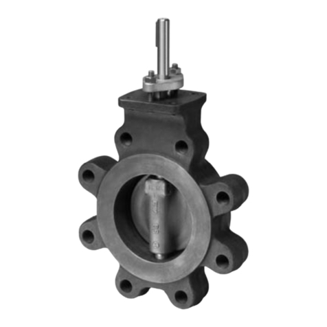
Belimo Energy Valve EV015R+BAC Instruction manual

Belimo

Belimo Energy Valve EV015R+BAC Instruction manual

Belimo BKS24-1B Quick start guide

Belimo

Belimo BKS24-1B Quick start guide

Popular Control Unit manuals by other brands
Spirax Sarco DLV7 Installation and maintenance instructions

Spirax Sarco

Spirax Sarco DLV7 Installation and maintenance instructions

Bardiani Valvole BBZS5 Instruction, use and maintenance manual

Bardiani Valvole

Bardiani Valvole BBZS5 Instruction, use and maintenance manual

Eaton ZB150 Series Instruction leaflet

Eaton

Eaton ZB150 Series Instruction leaflet

Texecom Premier Elite Installation Instructions and Specifications

Texecom

Texecom Premier Elite Installation Instructions and Specifications

Immergas MAGIS PRO 5 ERP Instruction and recommendation booklet

Immergas

Immergas MAGIS PRO 5 ERP Instruction and recommendation booklet

Raita BioModule Manual Installation

Raita

Raita BioModule Manual Installation

AAF SAAFShield Installation, operation and maintenance instructions

AAF

AAF SAAFShield Installation, operation and maintenance instructions

Digital Equipment Pro-face GP-377R Series user manual

Digital Equipment

Digital Equipment Pro-face GP-377R Series user manual

Eaton XIOC-SER Instruction leaflet

Eaton

Eaton XIOC-SER Instruction leaflet

ViewSonic VS16935 quick start guide

ViewSonic

ViewSonic VS16935 quick start guide

Avidsen COMBO Kit SS1 manual

Avidsen

Avidsen COMBO Kit SS1 manual

Smartgen SGB100 user manual

Smartgen

Smartgen SGB100 user manual

Kuppersbusch E5 technical information

Kuppersbusch

Kuppersbusch E5 technical information

WCP Swerve X user guide

WCP

WCP Swerve X user guide

Watts AMES 933GD manual

Watts

Watts AMES 933GD manual

AccuStream AccuValve On/Off Valve manual

AccuStream

AccuStream AccuValve On/Off Valve manual

ADC H2TU-C-202 Quick installation

ADC

ADC H2TU-C-202 Quick installation

Lucent Technologies LINEAGE 2000 CP5 product manual

Lucent Technologies

Lucent Technologies LINEAGE 2000 CP5 product manual

manuals.online logo
manuals.online logoBrands
  • About & Mission
  • Contact us
  • Privacy Policy
  • Terms and Conditions

Copyright 2025 Manuals.Online. All Rights Reserved.