Comunello Automation CU-230V-2M User manual

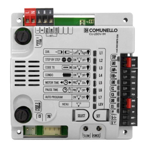
CU - 230V - 2M
INSTALLATION AND USER’S MANUAL
Control unit
comunello.com
ISTRUZIONI D’USO E DI INSTALLAZIONE
INSTALLATIONS-UND GEBRAUCHSANLEITUNG
INSTRUCIONS D’UTILISATION ET D’INSTALLATION
INSTRUCCIONES DE USO Y DE INSTALACION
ИНСТРУКЦИЯ ПО МОНТАЖУ Cod. 91300137 Rev. 00 - 26.06.14

2COMUNELLO ®Copyright 2014 - All right reserved
ID LED
L1 PGM CODE ON OFF
L2 FOTOTEST ON OFF
L3 DECELERATION OFF ON
L4 LEAVES DELAY ON OFF
L5 RELEASE STROKE ON OFF
L6 SLAM LOCK ON OFF
L7 COURTESY LIGHT ON OFF
LEV MENÙ 1 FLASH
ID LED
L1 SOFT STOP ON OFF
L2 SOFT START ON OFF
L3 DS1 IN OPEN ON OFF
L4 HOLD-TO-RUN ON OFF
L5 FOLLOW ME ON OFF
L6 PAUSE FLASHING ON OFF
L7 ALWAYS CLOSE ON OFF
LEV MENÙ 2 FLASHES
ID LED
L1 DELAY Operator 1 delay Operator 2 delay
L2 STEP BY STEP Step-by-Step Automatic
L3 CODE TX Code entered No code
L4 CONDO ON OFF
L5 MOTOR TIME Programmed time 30 sec.
L6 PAUSE TIME With automatic closing Without automatic closing
L7 PED TIME ON OFF
LEV MENÙ ON
MENÙ LIST
MAIN MENÙ
EXTENDED MENÙ 1
EXTENDED MENÙ 2

3
COMUNELLO ®Copyright 2014 - All right reserved
FIG. 4
TABELLA CONNESSIONI CAVI AG01 - WIRES CONNECTION TABLE AG01
BASIC 230V
ID Description Cable type Lenght (1m to 20m) Lenght (20m to 50m)
1Main power supply
FG7 CEI 20-22
CEI EN 50267-2-1
3Gx1,5mm2 3Gx2,5mm2
6A Motor power supply 4Gx1,5mm2 4Gx2,5mm2
2 Flashing light 2x0,5mm2 2x1,0mm2
4A , 5A Photocell TX 2x0,5mm2 2x1,0mm2
4B , 5B Photocell RX 4x0,5mm2 4x1,0mm2
7 Key selector 3x0,5mm2 3x1,0mm2
3 Antenna RG58 max 20m

4COMUNELLO ®Copyright 2014 - All right reserved
LINEA
POWER SUPPLY
2P+T 230V 50Hz
M
TRASFORMATORE
TRANSFORMER
230 / 24.5V - 0.4A; 12.5V - 0.17A
12.5V
24.5V
CN2
PULSANTE APRI-CHIUDI (N.O.)
PUSCH BUTTON (N.O.)
ALIMENTAZIONE FOTOCELLULE
PHOTCELL POWER
24V 5W
FOTOCELLULA
PHOTCELL
DS 1 (N.C.) IN CHIUSURA
FOTOCELLULA
PHOTCELL
DS 2 (N.C.) IN APERTURA
LAMPEGGIANTE
FLASHING LIGHT
24V 4W
SEL
F2 SET
ELETTROSERRATURA (contatto pulito N.O.)
ELECTRIC LOCK
M
MOTORE 2
MOTOR 2
230V 50HZ
MOTORE 1
MOTOR 1
230V 50HZ
CN1
PULSANTE PEDONALE (N.O.)
PEDESTRIANPUSH BUTTON (N.O.)
CN4
CN3
F1
ANTENNA
FOT+
GND
LAMP
ELS
ELS
DS1
PED
GND
DS2
PP
ANT-
ANT+
L
N
OP1
CM1
CL1
OP2
CM2
CL2

5
COMUNELLO ®Copyright 2014 - All right reserved
ITALIANO
CN1
F1
L
N
OP1
CM1
CL1
OP2
CM2
CL2
ABACUS - connection diagram of the motors
• DELAY LED OFF = DELAY OF THE MOTOR n.2
1
1
2
2
Conguration:
• DELAY LED ON = DELAY OF THE MOTOR n.1
OPEN with OP1
COMMON with CM1
CLOSED with CL1
OPEN with OP2
COMMON with CM2
CLOSED with CL2

6COMUNELLO ®Copyright 2014 - All right reserved
CN1
F1
L
N
OP1
CM1
CL1
OP2
CM2
CL2
RAM - connection diagram of the motors
• DELAY LED OFF = DELAY OF THE MOTOR n.2
1
1
2
2
Conguration:
• DELAY LED ON = DELAY OF THE MOTOR n.1
OPEN with OP1
COMMON with CM1
CLOSED with CL1
OPEN with OP2
COMMON with CM2
CLOSED with CL2

7
COMUNELLO ®Copyright 2014 - All right reserved
CN2
SEL
F2 SET
FOT+
GND
LAMP
ELS
ELS
DS1
PED
GND
DS2
PP
ANT-
ANT+
L
N
OP1
CM1
CL1
OP2
CM2
CL2
CONDOR - connection diagram of the motors [1/2]
• DELAY LED OFF = DELAY OF THE MOTOR n.2
Conguration - MASTER ON THE LEFT, SLAVE ON THE RIGHT
MOTOR n.1 WITH CONTROL UNIT (on the left)
BLACK with OP1
COMMON with CM1
BROWN with CL1
MOTOR n.2 WITHOUT CONTROL UNIT (on the right)
OPEN with CL2
COMMON with CM2
CLOSED with OP2
1
1
2
2
• DELAY LED ON = DELAY OF THE MOTOR n.1
Brown
Blue
Black

8COMUNELLO ®Copyright 2014 - All right reserved
CN2
SEL
F2 SET
FOT+
GND
LAMP
ELS
ELS
DS1
PED
GND
DS2
PP
ANT-
ANT+
L
N
OP1
CM1
CL1
OP2
CM2
CL2
Blue
1
2
1
2
CONDOR - [2/2]
• DELAY LED OFF = DELAY OF THE MOTOR n.1
• DELAY LED ON = DELAY OF THE MOTOR n.2
Congurazione - MASTER ON THE RIGHT, SLAVE ON THE LEFT
MOTOR n.2 WITHOUT CONTROL UNIT (on the left)
OPEN with OP2
COMMON on CM2
CLOSED on CL2
MOTOR n.1 WITH CONTROL UNIT (on the right)
[INVERT THE WIRES IN CONTROL UNIT]
BROWN with OP1
BLUE with CM1
BLACK with CL1
Black Brown

9
COMUNELLO ®Copyright 2014 - All right reserved
EAGLE - connection diagram of the motors
• DELAY LED OFF = DELAY OF THE MOTOR n.2
• DELAY LED ON = DELAY OF THE MOTOR n.1
1
1
2
2
CN1
F1
L
N
OP1
CM1
CL1
OP2
CM2
CL2
Conguration - MOTOR n.1 ON THE LEFT, MOTOR n.2 ON THE RIGHT
MOTOR n.1 (on the left)
BROWN with CL1
BLUE with CM1
BLACK with OP1
MOTOR n.2 (on the right)
[INVERTED CONFIG. COMPARED TO MOTOR n.1]
BROWN with OP2
BLUE with CM2
BLACK with CL2
Brown
Brown
Blue
Blue
Black
Black

10 COMUNELLO ®Copyright 2014 - All right reserved
CN1
F1
L
N
OP1
CM1
CL1
OP2
CM2
CL2
CONDOR 500 - connection diagram of the motors
• DELAY LED OFF = DELAY OF THE MOTOR n.2
• DELAY LED ON = DELAY OF THE MOTOR n.1
Conguration - MOTOR n.1 ON THE LEFT, MOTOR n.2 ON THE RIGHT
1
1
2
2
MOTOR n.1 (on the left)
OPEN with OP1
COMMON with CM1
CLOSED with CL1
MOTOR n.2 (on the right)
[INVERTED CONFIG. COMPARED TO MOTOR n.1]
OPEN with CL2
COMMON with CM2
CLOSED with OP2

11
COMUNELLO ®Copyright 2014 - All right reserved
Fratelli Comunello S.p.A.
Azienda con Sistema Gestione Qualità certicato
UNI EN ISO 9001:2008.
(Certicato n° 50 100 11235 Rev. 01)
CU - 230V - 2M
ISTRUZIONI D’USO E DI INSTALLAZIONE
DICHIARAZIONE DEL FABBRICANTE
Fabbricante: Fratelli Comunello Spa
Indirizzo: Via Cassola 64, 36027 Rosà (VI) - Italia
Dichiara che la centrale di comando CU 230V 2M
• è costruita per essere incorporata in una macchina o per essere assemblata con altri macchinari per costituire una macchina considerata
dalla Direttiva 98/37 CE;
• è conforme alle condizioni delle seguenti altre Direttive CE:
Direttiva bassa tensione 2006/95 CE e successivi emendamenti secondo la normativa armonizzata EN 60335-1
Direttiva compatibilità elettromagnetica 2004/108/CE e successivi emendamenti secondo le normative EN 61000-6-2 e EN 61000-6-3
• è conforme alle normative EN 301489-1, EN 301489-3, EN 300220-2, EN 622233, EN 13241-1, EN 12445, EN 12453.
Inoltre dichiara che non è consentito mettere in servizio la centrale no a che la macchina in cui sarà incorporata o di cui diverrà
componente sia stata identicata e ne sia stata dichiarata la conformità alle condizioni della Direttiva 98/37 CE e alla legislazione nazionale
che la traspone.
Luca Comunello
Rappresentante legale della Fratelli Comunello

12 COMUNELLO ®Copyright 2014 - All right reserved
AVVERTENZE
• La centrale non presenta nessun tipo di dispositivo di sezionamento
della linea elettrica 230 Vac, sarà quindi cura dell’installatore prevedere
nell’impianto un dispositivo di sezionamento. È necessario installare un
interruttore omnipolare con categoria III di sovratensione. Esso deve
essere posizionato in modo da essere protetto contro le richiusure
accidentali secondo quanto previsto al punto 5.2.9 della EN 12453.
Il cablaggio dei vari componenti elettrici esterni alla centralina deve
essere effettuato secondo quanto prescritto dalla normativa EN 60204-1
e dalle modiche a questa apportata dal punto 5.2.7 della EN 12453.
I cavi di alimentazione possono avere un diametro massimo di 14 mm;
il ssaggio dei cavi di alimentazione e di collegamento, deve essere
garantito tramite l’assemblaggio di pressacavi fornibili “optional”.
• Per i cavi di alimentazione si raccomanda di utilizzare cavi essibili sotto
guaina isolante in policloroprene di tipo armonizzato (H05RN-F) con
sezione minima dei conduttori pari a 1 mm2.
• Utilizzare in fase di installazione esclusivamente cavi in doppio isolamento
(cavi con guaina) sia per i collegamenti a tensione di rete (230V) che
per i collegamenti in bassissima tensione di sicurezza SELV. Utilizzare
esclusivamente canalette in plastica, distinte per i cablaggi in bassa
tensione (230V) e per i cablaggi in bassissima tensione di sicurezza
(SELV).
• I conduttori a bassissima tensione di sicurezza devono essere
sicamente separati (almeno 4 mm in aria) dai conduttori a tensione
di rete, oppure devono essere adeguatamente isolati con isolamento
supplementare avente spessore di almeno 1 mm.
• Prevedere a monte della rete di alimentazione dell’automazione un
dispositivo che assicuri la disconnessione completa omnipolare della
rete, con una distanza di apertura dei contatti in ciascun polo di almeno
3mm. Tali dispositivi di disconnessione devono essere previsti nella rete
di alimentazione conformemente alle regole di installazione e devono
essere direttamente collegati ai morsetti di alimentazione.
• Fare attenzione, in fase di foratura dell’ involucro esterno per far passare
i cavi di alimentazione e di collegamento, e di assemblaggio dei
pressacavi, ad installare il tutto in modo da mantenere il più possibile
inalterate le caratteristiche di grado IP della scatola. Prestare inoltre
attenzione a ssare i cavi in modo che siano ancorati in modo stabile, e
a non danneggiare la scheda con la foratura (g. 3B).
• L’involucro nella parte posteriore è provvisto di opportune predisposizioni
per ssaggio a muro (predisposizione per fori per ssaggio mediante
tasselli o fori per ssaggio mediante viti). Prevedere e implementare tutti
gli accorgimenti per una installazione che non alteri il grado IP.
• L’eventuale montaggio di una pulsantiera per il comando manuale deve
essere fatto posizionando la pulsantiera in modo che l’utente non venga
a trovarsi in posizione pericolosa.
• Il motoriduttore usato per muovere il cancello deve essere conforme a
quanto prescritto al punto 5.2.7 della EN 12453.
• L’uscita FOTO+ (CN2) è necessariamente dedicata all’alimentazione
delle fotocellule, non è consentito l’utilizzo per altre applicazioni.
• La centrale ad ogni ciclo di manovra può effettuare il test di
funzionamento delle fotocellule, garantendo una protezione al guasto
dei dispositivi antischiacciamento di Categoria 2 secondo quanto
prescritto al punto 5.1.1.6. della EN 12453. Quindi se i dispositivi di
sicurezza non vengono connessi e/o non sono funzionanti la centrale
non è abilitata al funzionamento.
• L’apparecchio può essere utilizzato da bambini di età non inferiore a
8 anni e da persone con ridotte capacità siche, sensoriali o mentali,
o prive di esperienza o della necessaria conoscenza, purché sotto
sorveglianza oppure dopo che le stesse abbiano ricevuto istruzioni
relative all’uso sicuro dell’apparecchio e alla comprensione dei pericoli
ad esso inerenti. I bambini non devono giocare con l’apparecchio. La
pulizia e la manutenzione destinata ad essere effettuata dall’utilizzatore
non deve essere effettuata da bambini senza sorveglianza.
Per un corretto funzionamento della parte radio ricevente, in caso di utilizzo
di due o più centrali, si consiglia l’installazione ad una distanza di almeno 3
metri l’una dall’altra.
Tutte le operazioni che richiedono l’apertura dell’involucro (collegamento
cavi, programmazione, ecc.) devono essere eseguite in fase di installazione
da personale qualicato.
IMPORTANTE PER L’UTENTE
• Il dispositivo non deve essere utilizzato da bambini o da persone con
ridotte capacità psico-siche, almeno che non siano supervisionati o
istruiti sul funzionamento e le modalità di utilizzo.
• Non consentire ai bambini di giocare con il dispositivo e tenere lontano
dalla loro portata i radiocomandi.
• ATTENZIONE! conservare questo manuale d’istruzioni e rispettare le
importanti prescrizioni di sicurezza in esso contenute. Il non rispetto
delle prescrizioni potrebbe provocare danni e gravi incidenti.
Esaminare frequentemente l’impianto per rilevare eventuali segni di
danneggiamento. Non utilizzare il dispositivo se è necessario un intervento
di riparazione.
CARATTERISTICHE TECNICHE
Alimentazione: 230 V~50Hz 1600W max.
Uscita lampeggiante: 24 V~4W max.
Uscite motori: 230 V~2 x 500 W max.
Uscita elettro-serratura: Contatto pulito ( 24V 5A max.)
Alimentazione fotocellule: 24 V~5 W max.
Sicurezze e comandi in BT: 24 V---
Temperatura d’esercizio: -20 ÷ 55 °C
Ricevitore radio: 433 Mhz
Trasmettitori op.: 18 Bit o Rolling Code
Codici TX max. in memoria: 120 (CODE o CODE PED)
Dimensioni scheda: 100x105 mm
VERIFICHE PRELIMINARI
• Vericare che il prodotto all’interno dell’imballo sia integro ed in buone
condizioni.
• Vericare che il luogo di installazione sia idoneo e rispetti le dimensioni
minime riportate in FIG. 1.
INSTALLAZIONE
• Dopo aver forato la scatola ai quattro angoli ssare la centrale alla parete
(FIG. 2).
• Per il passaggio dei cavi forare la parte inferiore della scatola. (FIG. 3).
È consigliabile l’utilizzo di pressacavi.
COLLEGAMENTI ELETTRICI
CN1:
L: Ingresso linea 230 V~(Fase).
N: Ingresso linea 230 V~(Neutro).
MOT1 OPEN: Uscita Motore 1 apertura.
MOT1 COM: Uscita Motore 1 comune.
MOT1 CLOSE: Uscita Motore 1 chiusura.
MOT2 OPEN: Uscita Motore 2 apertura.
MOT2 COM: Uscita Motore 2 comune.
MOT2 CLOSE: Uscita Motore 2 chiusura.
CN2:
ELS: Uscita Elettroserratura contatto pulito
LAMP+: Uscita Lampeggiante ( 24 V~4W max )
FOTO+: Controllo e Alimentazione Fotocellule ( 24V~5W max )
GND: Alimentazione comune (GND)
DS2: Ingresso Dispositivo Sicurezza 2 (NC)
DS1: Ingresso Dispositivo Sicurezza 1 (NC)
GND: Ingresso GND comune
PED: Ingresso Pulsante Pedonale (NA)
PP: Ingresso Pulsante comando Apre/Chiude (NA)
ANT-: Ingresso Massa Antenna
ANT+: Ingresso Polo caldo Antenna
COLLEGAMENTI TRASFORMATORE
CN3 1st:
1: Ingresso Avvolgimento Primario Trasformatore 230 V~.
2: Ingresso Avvolgimento Primario Trasformatore 230 V~.
CN4 2nd:
1: Uscita SEC 1 Trasformatore 12,5V 0,17A tensioni a vuoto.
2: Uscita SEC 1 Trasformatore 12,5V 0,17A tensioni a vuoto.
3: Uscita SEC 2 Trasformatore 24,5V 0,4A tensioni a vuoto.
4: Uscita SEC 2 Trasformatore 24,5V 0,4A tensioni a vuoto.
CARATTERISTICHE FUNZIONALI
FUNZIONAMENTO AUTOMATICO PROGRAMMATO
Utilizzando sia il radiocomando che la pulsantiera in bassa tensione per

13
COMUNELLO ®Copyright 2014 - All right reserved
ITALIANO
l’azionamento del serramento, si otterrà il seguente funzionamento:
il primo impulso comanda l’apertura no allo scadere del tempo motore,
il secondo impulso comanda la chiusura del serramento; se si invia un
impulso prima dello scadere del tempo motore o del raggiungimento di uno
dei due necorsa, la centrale effettua l’inversione del moto sia nella fase
d’apertura sia in quella di chiusura.
FUNZIONAMENTO PASSO-PASSO:
Utilizzando sia il radiocomando che i pulsanti in bassa tensione per
l’azionamento del serramento, si otterrà il seguente funzionamento:
il primo impulso comanda l’apertura no allo scadere del tempo motore o
al raggiungimento del ne corsa d’apertura, il secondo impulso comanda
la chiusura del serramento; se si invia un impulso prima dello scadere del
tempo motore o del raggiungimento del necorsa apertura, la centrale
effettua l’arresto del moto ( se precedentemente programmato il tempo
di pausa, la centrale allo scadere effettua la richiusura automatica ). Un
ulteriore comando determina la ripresa del moto in senso opposto; se si
invia un impulso prima dello scadere del tempo motore o del raggiungimento
del necorsa chiusura, la centrale effettua sempre l’arresto del moto. Un
ulteriore comando determina la ripresa del moto in senso opposto.
Funzionamento Passo-Passo 1 (STOP PERMANENTE):
Utilizzando sia il radiocomando che i pulsanti in bassa tensione per
l’azionamento del serramento, si otterrà il seguente funzionamento: il
primo impulso comanda l’apertura no allo scadere del tempo motore o
al raggiungimento del ne corsa d’apertura, il secondo impulso comanda
la chiusura del serramento; se si invia un impulso prima dello scadere del
tempo motore o del raggiungimento di uno dei due necorsa, la centrale
effettua sempre l’arresto del moto sia nella fase di apertura sia in quella di
chiusura ( anche se precedentemente programmato il tempo di pausa )
. Un ulteriore comando determina la ripresa del moto in senso opposto.
CHIUSURA AUTOMATICA:
La centrale permette di richiudere il serramento in modo automatico senza
l’invio di comandi supplementari. La scelta di questo funzionamento è
descritta nel modo di programmazione del Tempo di pausa.
FOTOCELLULE:
La centrale permette l’alimentazione ed il collegamento di fotocellule in
accordo alla direttiva EN 12453.
Ingresso DS1 (NC)
L’intervento delle fotocellule nella fase di apertura non viene considerato,
nella fase di chiusura provoca l’inversione del moto.
Ingresso DS2 (NC)
L’intervento nella fase di apertura provoca l’arresto momentaneo del
serramento, una volta liberato la centrale riprende la fase di apertura.
L’intervento in fase di chiusura provoca l’inversione del moto.
Per consentire un funzionamento rispondente alla Categoria 2 di EN 13849-
1 viene eseguito prima di ogni manovra un test delle fotocellule. Solo se
viene superato il test la centrale avvia la manovra: in caso contrario la
centrale non consente nessun movimento e ad ogni comando il lampeggio
di tutti i led di programmazione segnala la situazione di allarme
REGOLAZIONE FORZA DEL MOTORE (FORCE):
La centrale elettronica è dotata di un trimmer FORCE” per la regolazione
della Forza dei motori, completamente gestite dal microprocessore. La
regolazione può essere effettuata con un range da 50% al 100% della Forza
massima.
Per ogni movimento è previsto comunque uno spunto iniziale, alimentando
il motore per 2 secondi alla massima potenza anche se è inserita la
regolazione della forza del motore. Nota: lo spunto iniziale è disabilitato
automaticamente se abilitata la funzione di Soft Start.
ATTENZIONE: Una variazione del trimmer “FORCE” richiede la
ripetizione della procedura di apprendimento, in quanto potranno
variare i tempi di manovra e di rallentamento
RALLENTAMENTO (SLOW):
La funzione di rallentamento dei motori è usata nei cancelli per evitare la
battuta a forte velocità delle ante mobili al termine della fase di apertura e
chiusura.
La centrale consente durante la programmazione del Tempo Motore (vedi
menù Principale) anche la programmazione del rallentamento nei punti
desiderati (prima della totale apertura e chiusura).Tramite il trimmer “SLOW”
è possibile fare una regolazione suddivisa in tre livelli di ne intensità della
velocità durante la fase di rallentamento.
FUNZIONAMENTO CON TIMER:
La centrale permette di collegare al posto del pulsante di P.P. un timer.
Esempio: ore 08.00 il timer chiude il contatto e la centrale comanda
l’apertura, ore 18.00 il timer apre il contatto e la centrale comanda la
chiusura. Durante l’intervallo 08.00–18.00 al termine della fase di apertura la
centrale disabilita il lampeggiante, la chiusura automatica e i radiocomandi.
USCITA COMANDO ELETTROSERRATURA:
La centrale dispone di un contatto pulito in uscita per pilotare un
elettroserratura. Il contatto viene chiuso ad ogni movimento iniziale di
apertura per la durata di 2 sec
PROGRAMMAZIONE:
Tasto SELECT: seleziona il tipo di funzione da memorizzare, la selezione è
indicata dal lampeggio del Led.
Premendo più volte il tasto, è possibile posizionarsi sulla funzione desiderata.
La selezione resta attiva per 10 secondi, visualizzata dal led lampeggiante,
se trascorsi, la centrale ritorna allo stato originario.
Tasto SET: effettua la programmazione dell’informazione secondo il tipo di
funzione prescelta con il tasto SELECT.
IMPORTANTE: la funzione del tasto SET può anche essere sostituita dal
radiocomando se precedentemente programmato.
Programmazione abilitata solo a sicurezze non attive.
MENÙ PRINCIPALE
La centrale è fornita dal costruttore con la possibilità di selezionare alcune
funzioni importanti.
1. DELAY:
La centrale nella congurazione di default presenta la logica di “RITARDO
MOTORE 2”.
Per evitare di scollegare i cavi al ne di ritardare il motore 1 al posto del il
motore 2, procedere nel seguente modo: posizionarsi con il tasto SELECT
sul lampeggio del LED L1 e poi premere il tasto SET: il LED L1 si accenderà
permanentemente e la programmazione sarà completata. Ripetere
l’operazione se si desidera ripristinare la congurazione precedente.
2. STEP BY STEP:
La centrale nella congurazione di default presenta la logica di funzionamento
“ Automatico ” abilitato (LED NR 2 spento);
se si desidera abilitare la logica di funzionamento P/P “ Passo – Passo “,
procedere nel seguente modo: posizionarsi con il tasto SEL sul lampeggio
del LED NR 2. e poi premere il tasto SET:
il LED NR 2 si accenderà permanentemente e la programmazione sarà
conclusa. Se si desidera abilitare la logica di funzionamento P/P1 “ Passo
– Passo 1, ripetere l’operazione sopra descritta, premendo il tasto SEL
due volte (ottenendo il lampeggio veloce del LED NR 2) anziché una volta.
Ripetere l’operazione se si desidera ripristinare la congurazione iniziale.
3. CODE TX: (Codice del radiocomando)
La centrale permette di memorizzare no a 120 radiocomandi aventi codice
diverso fra loro di tipo sso o rolling code.
Programmazione:
La programmazione del codice di trasmissione è eseguita nel seguente
modo: posizionarsi con il tasto SELECT sul lampeggio del LED L3.
L1 DELAY Ritardo motore 1 Ritardo motore 2
L2 STEP BY STEP Passo – Passo/PP1 Automatico
L3 CODE TX Codice inserito Nessun codice
L4 CONDO ON OFF
L5 MOTOR TIME Tempo programmato 30 sec.
L6 PAUSE TIME Con chiusura automatica Senza chiusura automatica
L7 PED TIME ON OFF
LEV MENÙ ON

14 COMUNELLO ®Copyright 2014 - All right reserved
Durante la programmazione è possibile usare al posto del tasto SET, posto
sulla centrale, il tasto del radiocomando solamente se precedentemente
memorizzato
7. PED TIME (Program. tempo di lavoro pedonale 4 minuti max.):
La centrale è fornita dal costruttore con un tempo di lavoro del Motore
(Pedonale) predenito pari a 10 secondi e senza rallentamento.
Se occorre modicare il tempo di lavoro pedonale, la programmazione deve
essere effettuata a serramento chiuso nel seguente modo: posizionarsi con
il tasto SELECT sul lampeggio del LED L7 poi premere per un istante il
tasto SET, il Motore inizierà ciclo di Apertura; in corrispondenza del punto
iniziale desiderato di rallentamento premere nuovamente il tasto SET:
il LED L7 inizierà a lampeggiare più lentamente e il Motore effettuerà il
rallentamento; al raggiungimento della posizione desiderata premere il tasto
SET per concludere il ciclo di Apertura. A questo punto il LED L7 tornerà
a lampeggiare regolarmente e il Motore ripartirà in Chiusura; ripetere le
operazioni viste sopra, per la fase di Chiusura.
Se non si desidera che la centrale effettui il rallentamento, durante la
programmazione, al completamento del ciclo di apertura e chiusura,
premere il tasto SET due volte consecutivamente anziché una sola.
Durante la programmazione è possibile usare al posto del tasto SET, posto
sulla centrale, il tasto del radiocomando solamente se precedentemente
memorizzato.
MENÙ ESTESO 1
La centrale è fornita dal costruttore con la possibilità di selezione diretta
solamente delle funzioni del menù principale. Se si desidera abilitare
le funzioni descritte nel Menù Esteso 1, procedere nel seguente modo:
posizionarsi sul lampeggio del led LEV e premere 1 volta SET. Il led inizierà
a lampeggiare. In questo modo si avranno 30 secondi di tempo per
selezionare le funzioni del Menù Esteso 1 mediante l’uso dei tasti SELECT
e SET; trascorsi ulteriori 30 secondi la centrale ritorna al menù principale.
1. PGM CODE REMOTO (Programmazione Radiocomando a distanza):
La centrale consente la programmazione del codice di trasmissione, senza
intervenire direttamente sul tasto SELECT della centrale, ma eseguendo
l’operazione a distanza.
La programmazione del Radiocomando a distanza, si esegue nel seguente
modo: inviare in modo continuo per un tempo maggiore a 10 secondi il
codice di un radiocomando in precedenza memorizzato, allo stesso tempo
la centrale entra in modo programmazione come sopra descritto per
il LED L3 nel menù principale. Se ad essere inviato in modo continuo è
un codice pedonale precedentemente memorizzato la centrale entrerà in
programmazione di un nuovo codice pedonale.
La centrale è fornita dal costruttore con la programmazione del codice
di trasmissione a distanza disabilitata, se si desidera abilitare la funzione,
procedere nel seguente modo: assicurarsi di aver abilitato il Menù Esteso 1
(evidenziato dal lampeggio 1 0 1 0 1 del led LEV), posizionarsi con il tasto
SELECT sul lampeggio del led L1 poi premere il tasto SET, nello stesso
istante il led L1 si accenderà permanentemente e la programmazione sarà
conclusa. Ripetere l’operazione se si desidera ripristinare la congurazione
precedente.
2. FOTOTEST (Test fotocellule):
La centrale è fornita dal costruttore con il test delle fotocellule disabilitato.
Se si desidera abilitare tale test procedere nel seguente modo: assicurarsi
di aver abilitato il Menù Esteso 1, posizionarsi con il tasto SELECT sul
lampeggio del led L2, poi premere il tasto SET, il LED L2 si accenderà
permanentemente e la programmazione sarà conclusa. Ripetere
l’operazione se si desidera ripristinare la congurazione precedente.
3. RALLENTAMENTO:
Come detto precedentemente la centrale permette la programmazione
di una fase di rallentamento in apertura e chiusura. Qualora però non si
desideri avere alcun rallentamento, è possibile escluderlo. Se prima
di escludere il rallentamento esso era stato programmato mediante la
Premere 1 volta SET, il led modicherà il proprio lampeggio (1 0 1 0 più
lungo) indicando che si sta memorizzando il primo livello. Inviando il codice
prescelto con il radiocomando desiderato, il LED L3 resterà acceso
permanentemente indicando che la programmazione sarà completata.
Per memorizzare il codice per l’apertura pedonale / anta singola procedere
come di seguito: posizionarsi con il tasto SELECT sul lampeggio del LED L3.
Premere 2 volte consecutive SET, il led modicherà il proprio lampeggio (1 1
0 1 1 0) indicando che si sta memorizzando il codice pedonale. Inviando il
codice prescelto con il radiocomando desiderato, il LED L3 resterà acceso
permanentemente indicando che la programmazione sarà completata.
Nel caso che tutti i 120 codici siano stati memorizzati, ripetendo l’operazione
di programmazione, tutti i LED di programmazione inizieranno a lampeggiare
segnalando che non sono possibili ulteriori memorizzazioni.
Cancellazione:
Posizionarsi con SELECT sul LED L3; attivare il lampeggio del codice
da cancellare (CODE o PEDONALE identicati dal rispettivo lampeggio);
premere e tener premuto SET per un tempo > 5 s. Alla ne il led si spegnerà
per 2 sec e la procedura è completata. Se si eliminano tutti i codici sia
CODE che PEDONALI, il led rimarrà spento.
Se rimarranno memorizzati solo codici PEDONALI, il led lampeggerà in
modo diverso (1 1 1 1 0 1 1 1 1 0)
Regola del primo Radiocomando memorizzato:
Nella programmazione dei radiocomandi vige la seguente regola: se il primo
radiocomando ad essere memorizzato è un radiocomando di tipo rolling
code il ricevitore accetterà poi solo radiocomandi rolling code, garantendo
così una maggiore sicurezza antintrusione; se invece il primo radiocomando
ad essere memorizzato è un radiocomando a codice sso il ricevitore
accetterà poi sia radiocomandi a codice sso che radiocomandi rolling
code, controllando però di questi ultimi soltanto la parte ssa (perdendo in
sostanza la sicurezza del sistema rolling).
4. CONDO:
Il funzionamento Condominiale prevede che la centrale durante la fase
apertura o durante la pausa non senta i comandi provenienti dai Pulsanti e
dai radiocomandi. Nella fase di chiusura invece un comando proveniente
dai pulsanti o dai radiocomandi provoca l’inversione del moto. Questa
modalità di funzionamento è particolarmente utilizzata quando l’automazione
è comprensiva di un loop detector.
La centrale nella congurazione di default, presenta la funzione condominiale
disabilitata, se occorre abilitarla, procedere nel seguente modo: posizionarsi
con il tasto SELECT sul lampeggio del LED L4 e poi premere il tasto SET:
il LED L4 si accenderà permanentemente e la programmazione sarà
conclusa. Ripetere l’operazione se si desidera ripristinare la congurazione
precedente.
5. MOTOR TIME:
(Program. tempo di lavoro dei motori 4 minuti max.) La centrale è fornita
dal costruttore con un tempo di lavoro motore predenito pari a 30 sec.
e senza rallentamento. Se occorre modicare il tempo di lavoro motore,
la programmazione deve essere effettuata a serramento chiuso nel
seguente modo: posizionarsi con il tasto SELECT, sul lampeggio del
LED L5 poi premere per un istante il tasto SET, il Motore inizierà ciclo di
apertura, al raggiungimento del punto iniziale desiderato di rallentamento,
premere nuovamente il tasto SET, allo stesso tempo il motore effettua il
rallentamento no alla posizione desiderata, premere il tasto SET per
concludere il ciclo di apertura. Successivamente il LED L5 inizierà a
lampeggiare velocemente, ora ripetere l’operazione di programmazione del
tempo motore e rallentamento per il ciclo di chiusura. Se non si desidera
che la centrale effettui il rallentamento, durante la programmazione, al
completamento del ciclo di apertura e chiusura, premere il tasto SET due
volte consecutivamente anziché una sola.
Durante la programmazione è possibile usare al posto del tasto SET, posto
sulla centrale, il tasto del radiocomando solamente se precedentemente
memorizzato.
6. PAUSE TIME:
(Programmazione tempo chiusura aut. 4 min. max.) La centrale è fornita dal
costruttore senza chiusura automatica. Se si desidera abilitare la chiusura
automatica, procedere nel seguente modo: posizionarsi con il tasto SELECT
sul lampeggio del LED L6 e premere per un istante il tasto SET, attendere
poi per un tempo uguale a quello desiderato; premere nuovamente per un
istante il tasto SET, nello stesso momento si determinerà la memorizzazione
del tempo di chiusura automatica e il LED L6 sarà acceso sso. Se si
desidera ripristinare la condizione iniziale (senza chiusura automatica),
posizionarsi sul lampeggio del LED L6 poi premere consecutivamente per
2 volte il tasto SET in un intervallo di tempo di 2 secondi. Il led si spegnerà
e l’operazione sarà conclusa.
L1 PGM CODE ON OFF
L2 FOTOTEST ON OFF
L3 RALLENTAMENTO OFF ON
L4 RITARDO ANTE ON OFF
L5 COLPO D'ARIETE ON OFF
L6 COLPO IN CHIUSURA ON OFF
L7 LUCE DI CORTESIA / PRELAMPEGGIO ON OFF
LEV MENÙ 1 LAMPEGGIO

15
COMUNELLO ®Copyright 2014 - All right reserved
ITALIANO
solamente delle funzioni del menù principale. Se si desidera abilitare
le funzioni descritte nel Menù Esteso 2, procedere nel seguente modo:
posizionarsi sul lampeggio del LED LEV e premere 2 volte SET. Il led inizierà
a lampeggiare in modo alternato 1 1 0 1 1 0 1 1 0. in questo modo si
avranno 30 secondi di tempo per selezionare le funzioni del Menù Esteso
2 mediante l’uso dei tasti SELECT e SET, poi dopo ulteriori 30 secondi la
centrale ritorna al menù principale.
1. SOFT STOP:
La centrale è fornita dal costruttore con la funzione Soft Stop disabilitata. Se
si desidera abilitare la funzione, procedere nel seguente modo: assicurarsi
di aver abilitato il Menù Esteso 2 posizionarsi con il tasto SEL sul lampeggio
del LED L1 e poi premere il tasto SET, nello stesso istante il LED L1 si
accenderà permanentemente e la programmazione sarà conclusa. In
questo modo, la centrale alla ne del moto, porterà la forza a zero in modo
graduale entro 2 secondi. Ripetere l’operazione se si desidera ripristinare la
congurazione precedente.
2. SOFT START:
La centrale è fornita dal costruttore con la funzione Soft Start disabilitata. Se
si desidera abilitare la funzione, procedere nel seguente modo: assicurarsi
di aver abilitato il Menù Esteso 2 posizionarsi con il tasto SELECT sul
lampeggio del LED L2 e poi premere il tasto SET, nello stesso istante il LED
L2 si accenderà permanentemente e la programmazione sarà conclusa. In
questo modo, la centrale ad ogni inizio di moto, controllerà la partenza del
motore, portando la forza in modo graduale, dal minimo al valore impostato
dal trimmer “FORCE” nei primi 2 secondi di funzionamento. Ripetere
l’operazione se si desidera ripristinare la congurazione precedente.
Nota: quando abilitata la funzione Soft Start la centrale disabilita
automaticamente lo Spunto Iniziale e viceversa.
3. DS1 IN APRE:
La centrale consente di modicare il funzionamento dell’ingresso DS1. Se
si desidera che SAFE 1 intervenga anche in apertura (arresto momentaneo
del serramento, una volta liberato la centrale riprende il moto in apertura),
procedere nel seguente modo: assicurarsi di aver abilitato il Menù Esteso
2 posizionarsi con il tasto SEL sul lampeggio del LEDL3 e poi premere il
tasto SET: il LED L3 sii accenderà permanentemente e la programmazione
sarà conclusa.
Ripetere l’operazione se si desidera ripristinare la congurazione iniziale.
4. UOMO PRESENTE:
La centrale permette di impostare il funzionamento “Uomo presente”. Se
si desidera tale modalità di funzionamento procedere nel seguente modo:
assicurarsi di aver abilitato il Menù Esteso 2posizionarsi con il tasto SELECT
sul lampeggio del LED L4. e poi premere il tasto SET: il LED L4 si accenderà
permanentemente e l’operazione sarà conclusa.
In questo modo, utilizzando sia i radiocomandi che i Pulsanti per
l’azionamento del serramento, si otterrà il seguente funzionamento:
occorrerà mantenere costantemente attivato il comando desiderato per
ottenere il moto del serramento. Il rilascio del comando provocherà l’arresto
immediato del moto. Ripetere l’operazione se si desidera ripristinare la
congurazione precedente.
5. FOLLOW ME
La centrale permette di impostare il funzionamento “Follow me”: tale
funzione, programmabile solo se è già stato programmato un Tempo di
Pausa, prevede di ridurre il tempo di Pausa a 5 sec. dopo il disimpegno
della fotocellula DS1, ossia il serramento si richiude 5 sec. dopo che
l’utilizzatore è transitato. Per attivare tale funzione procedere nel seguente
modo: assicurarsi di essere nel Menù 2 posizionarsi con il tasto SELECT
sul lampeggio del LED L5 e poi premere il tasto SET: il LED L5 si accenderà
permanentemente e la programmazione sarà conclusa. Ripetere
l’operazione se si desidera ripristinare la congurazione precedente.
funzione di Programmazione dei Tempi Motore sarà necessario ripetere
la programmazione da capo. Se si desidera escludere il rallentamento
procedere nel seguente modo :assicurarsi di aver abilitato il Menù Esteso 1
, posizionarsi con il tasto SELECT sul lampeggio del LED 3 e poi premere il
tasto SET: Il LED L3 si accenderà permanentemente e la programmazione
sarà conclusa. Ripetere l’operazione se si desidera ripristinare la
congurazione precedente.
4. RITARDO ANTE:
(Programmazione ritardo anta 15 sec. max.) La centrale è fornita dal
costruttore senza ritardo ante di apertura e chiusura. Nel caso di utilizzo nella
congurazione per l’automazione a 2 motori, potrebbe essere necessario
inserire un tempo di ritardo delle ante; la programmazione deve essere
effettuata a serramento chiuso nel seguente modo: assicurarsi di aver
abilitato il Menù Esteso 1, posizionarsi con il tasto SELECT sul lampeggio
del led L4 premere per un istante il tasto SET, poi attendere per un tempo
uguale a quello desiderato, premere nuovamente per un istante il tasto
SET, nello stesso momento si determinerà la memorizzazione del tempo
di ritardo ante di apertura sso a 4 secondi, del tempo di ritardo ante di
chiusura per il tempo programmato ed il LED L4 sarà acceso sso.
Se si desidera ripristinare la condizione iniziale (senza ritardo ante),
posizionarsi sul lampeggio del LED L4 poi premere consecutivamente per
2 volte il tasto SET in un intervallo di tempo di 2 secondi, nello stesso tempo
il Led si spegnerà e l’operazione sarà conclusa.
5. COLPO D’ARIETE:
La centrale è fornita dal costruttore con la funzione di Colpo d’Ariete
disabilitata. Se si desidera abilitare la funzione di Colpo d’Ariete alla
massima potenza, procedere nel seguente modo: assicurarsi di aver
abilitato il Menù Esteso 1, posizionarsi con il tasto SELECT sul lampeggio
del LED L5. poi premere il tasto SET, nello stesso istante il LED L5 si
accenderà permanentemente e la programmazione sarà conclusa. Se
si desidera abilitare la funzione di Colpo d’Ariete alla potenza impostata
tramite il Trimmer “FORCE”, ripetere l’operazione sopra descritta,
premendo il tasto SELECT due volte (ottenendo il lampeggio veloce del
LED L5 anziché una volta. Ripetere l’operazione se si desidera ripristinare
la congurazione iniziale.
In questo modo possiamo facilitare lo sblocco della serratura e quindi
permettere la corretta esecuzione della fase di apertura. La centrale infatti
prima d’iniziare la fase di apertura invia un comando di chiusura per 2
secondi con potenza relativa alla scelta selezionata.
6. COLPO IN CHIUSURA:
La centrale è fornita dal costruttore con la funzione di Colpo in Chiusura
disabilitata. Tale funzione consiste nell’aggiungere, nel caso sia presente
una fase di rallentamento in chiusura, un tempo di 1 secondo, alla
potenza massima oppure alla potenza selezionata mediante trimmer
“FORCE”, in modo da sormontare un’eventuale serratura installata. Se si
desidera abilitare la funzione di Colpo in Chiusura alla massima potenza,
procedere nel seguente modo: assicurarsi di aver abilitato il Menù Esteso
1, posizionarsi con il tasto SELECT sul lampeggio del LED L6 e poi premere
il tasto SET: il led L6. si accenderà permanentemente e la programmazione
sarà conclusa. Se si desidera abilitare la funzione di Colpo in Chiusura alla
potenza impostata tramite il Trimmer “FORCE”, ripetere l’operazione sopra
descritta, premendo il tasto SELECT due volte (ottenendo il lampeggio
veloce del LED L6.) anziché una volta. Ripetere l’operazione se si desidera
ripristinare la congurazione iniziale.
7. PRELAMPEGGIO/LUCE DI CORTESIA:
La centrale è fornita dal costruttore con le funzioni Prelampeggio e Luce
di Cortesia disabilitate. Se si desidera abilitare la funzione Prelampeggio,
procedere nel seguente modo: assicurarsi di aver abilitato il Menù Esteso
1, posizionarsi con il tasto SEL sul lampeggio del LED L7 e poi premere
il tasto SET: il led si accenderà permanentemente e la programmazione
sarà conclusa. Se si desidera abilitare la funzione di Luce di Cortesia,
ripetere l’operazione sopra descritta, premendo il tasto SELECT due
volte (ottenendo il lampeggio veloce del LED) anziché una volta. Ripetere
l’operazione se si desidera ripristinare la congurazione iniziale.
Funzionamento Prelampeggio: L’uscita Lampeggiatore 24 Vac 4W max.
si attiverà sempre 3 secondi prima che l’automazione dia inizio a qualsiasi
movimento.
Funzionamento Luce di Cortesia: L’uscita Lampeggiatore 24 Vac 4W
max. si attiverà per la durata di 3 minuti, ogni qualvolta che sarà impartito
un comando di apertura.
MENÙ ESTESO 2
La centrale è fornita dal costruttore con la possibilità di selezione diretta
L1 SOFT STOP ON OFF
L2 SOFT START ON OFF
L3 DS1 IN APRE ON OFF
L4 UOMO PRESENTE ON OFF
L5 FOLLOW ME ON OFF
L6 LAMP PAUSA ON OFF
L7 CHIUDI SEMPRE ON OFF
LEV MENÙ 2 LAMPEGGI

16 COMUNELLO ®Copyright 2014 - All right reserved
6. LAMP PAUSA
La centrale è fornita dal costruttore con il funzionamento del Lampeggiante
durante il Tempo di Pausa disabilitato. Se si desidera abilitare il
funzionamento, procedere nel seguente modo: assicurarsi di aver abilitato
il Menù Esteso 2posizionarsi con il tasto SELECT sul lampeggio del LED
L6 e poi premere il tasto SET: il LED L6 si accenderà permanentemente
e la programmazione sarà conclusa. Ripetere l’operazione se si desidera
ripristinare la congurazione precedente.
7. CHIUDI SEMPRE
La centrale permette di impostare il funzionamento “Chiudi Sempre”: tale
funzione, programmabile solo se è già stato programmato un Tempo
di Pausa, interviene dopo una mancanza di alimentazione; se viene
rilevato che il cancello è aperto si avvia automaticamente una manovra di
chiusura preceduta da 5s. di prelampeggio. Se si desidera tale modalità
di funzionamento procedere nel seguente modo: assicurarsi di essere
nel Menù 2, posizionarsi con il tasto SEL sul lampeggio del LED L7
e poi premere il tasto SET: il LED L7 si accenderà permanentemente e
l’operazione sarà conclusa. Ripetere l’operazione se si desidera ripristinare
la congurazione precedente.
RESET
Nel caso sia opportuno ripristinare la centrale alla congurazione di fabbrica,
premere il tasto SELECT e SET in contemporanea, allo stesso tempo si
otterrà l’accensione contemporanea di tutti i led ROSSI di segnalazione e
subito dopo lo spegnimento.
DIAGNOSTICA
Test Fotocellula:
La centrale è predisposta per la connessione di dispositivi di sicurezza
che rispettano il punto 5.1.1.6 della normativa EN 12453. Ad ogni ciclo di
manovra viene effettuato il test di funzionamento della fotocellula collegata.
Nel caso di mancato collegamento e/o non funzionamento, la centrale non
abilita il movimento del serramento ed evidenzia visivamente il fallimento del
test effettuando il lampeggio contemporaneo di tutti i Led di segnalazione.
Una volta ripristinato il corretto funzionamento della fotocellula, la c entrale è
pronta per il normale utilizzo. Ciò garantisce un monitoraggio contro i guasti
conforme alla Categoria 2 della EN 954-1.
Test input comandi:
In corrispondenza ad ogni ingresso di comando in bassa tensione,
la centrale dispone di un LED di segnalazione, in modo tale da poter
controllare rapidamente lo stato.
Logica di funzionamento: LED acceso ingresso chiuso, LED spento
ingresso aperto.

17
COMUNELLO ®Copyright 2014 - All right reserved
ENGLISH
Fratelli Comunello S.p.A.
Company with certied Quality Management System
UNI EN ISO 9001:2008.
(Certicate n° 50 100 11235 Rev. 01)
CU - 230V - 2M
INSTALLATION AND USER’S MANUAL
MANUFACTURER’S DECLARATION
Manufacturer: Fratelli Comunello Spa
Address: Via Cassola 64, 36027 Rosà (VI) - Italy
Declares that the CU 230V 2M control unit:
• is designed to be incorporated in other machinery or assembled with other machinery to form a complex installation as described in
Directive 98/37 EC;
• is in compliance with the provisions set down in the additional EC Directives:
“Low voltage” Directive 2006/95 EC as amended in accordance with harmonized standard EN 60335-1
“Electromagnetic compatibility” Directive 2004/108/EC as amended in accordance with standards EN 61000-6-2 and EN 61000-6-3
• is in compliance with standards EN 301489-1, EN 301489-3, EN 300220-2, EN 622233, EN 13241-1, EN 12445, and EN 12453
and further declares that it is prohibited to commission the device until the machinery in which it will be incorporated or of which it will
become a component has been identied and its conformity has been declared in compliance with the provisions of Directive 98/37 EC
and the national legislation that implements the provisions of the Directive.
Luca Comunello
Fratelli Comunello legal representative

18 COMUNELLO ®Copyright 2014 - All right reserved
PRESCRIPTIONS
The control unit is not equipped with a device for disconnection of the
230 Vac power supply line. It is therefore the responsibility of the installer
to t a disconnection device in the electrical system. The disconnection
device must be of the category III overvoltage all-pole circuit breaker.
This device must be positioned in such a way as to protect it against
inadvertent reconnection in compliance with the requirements of EN
12453 point 5.2.9. Wiring of the external electrical devices to the
control unit must be carried out in compliance with the prescriptions
of EN 60204-1 as amended by EN 12453 point 5.2.7. The maximum
diameter of power feeding cables is 14 mm; xing of power feeding and
connection cables must be assured by tting cable glands, which can
be supplied as optionals.
• The power input cables must be of the standardized exible type with
polychloroprene sheath (H05RN-F) having minimum conductor size of 1
mm2.
• During the installation operations, take care to use cable with double
insulation only (sheathed cables) for both of mains voltage connections
(230V) and extra-low voltage connections (SELV). Use exclusively
plastic cable trays, separated for mains voltage wiring (230V) and extra-
low voltage wiring (SELV).
• The extra low voltage conductors must be physically separated (at
least 4 mm in air) from the mains voltage wires, or shall be adequately
insulated with extra insulation with a thickness of at least 1 mm.
• Upstream of main supply, install a device that ensures the complete
omnipolar disconnection (cut-off switch) of the power supply, with a
contact opening gap of at least 3mm in each pole. These disconnecting
devices shall be places in the power supply wiring in compliance with
the installation standards and must be directly connected to the supply
terminals.
• When drilling the outer case to insert the power and connection cables
and when tting the cable glands, take care to install all the parts in
a manner that maintains the IP protection characteristics of the box
unchanged as far as possible. Ensure the cables are xed in a stable
and secure manner.
• The rear of the box is equipped with knockouts for wall xing (knockouts
for xing holes using anchor bolts or holes for xing with screws). Take
all the measures required to ensure the installation procedures do not
affect the IP rating.
• If required, a pushbutton panel for manual control of the gate must be
installed in a position such as to ensure the user is not placed in danger.
• The operator utilized to move the gate must be in compliance with the
prescriptions of EN 12453, point 5.2.7.
• Foto+ output must be used for photocells. Alternative uses of this output
are not permitted.
• At each operating cycle, the control unit can test the photocells
operation to ensure protection against failure of anti-crushing protective
devices according to Category 2 in compliance with the prescriptions
of EN 12453 point 5.1.1.6. It follows that if the safety devices are not
connected or are faulty, operation of the control unit will be inhibited.
• The device can be used by children no older than 8 years old and
people with reduced physical, sensory or mental capabilities, or lack
of experience or without the required knowledge, but only under
surveillance or after having received instructions about the safe use of
the device and the hazards inherent in it. Children should not play with
the device. Cleaning and maintenance should not be carried out by
children without supervision.
For correct operation of the radio receiver section, when using two or more
control units it is good practice to install them at a minimum distance of 3
metres from one another.
All operations that require the control unit box to be opened (connection of
cables, programming, etc.) must be carried out by expert personnel at the
time of installation.
IMPORTANT INFORMATION FOR USERS
• The device must not be used by minors or psychologically-physically
differently-abled persons unless they are supervised or duly instructed
on the operation and methods of use.
• Do not let children play with the device and keep the remotes out of their
reach.
• IMPORTANT: keep this instruction manual and comply with the safety
prescriptions set down herein. Failure to comply with the prescriptions
may cause damage and serious accidents.
Frequently examine the system to identify any signs of damage. Do not use
the device if the enclosure is in need of repair (re-programming, repair or
modication of the installation); contact technical service.
TECHNICAL SPECIFICATIONS
Power supply: 230 V~50Hz 1600W max.
Flashing light output: 24 V~4W max.
Operator outputs: 230 V~2 x 500 W max.
Electric lock output: Voltage-free contact (24V 5A max.)
Photocells power supply: 24 V~5 W max.
LV safeties and controls: 24 Vcc
Working temperature: -20 ÷ 55 °C
Radio receiver: 433 Mhz
Transmitters: 18 Bit o Rolling Code
Max TX codes stored in memory: 120 (CODE o CODE PED)
Board dimensions: 100x105 mm
PRELIMINARY CHECKS
• Check that the product in the pack is intact and in good condition.
• Check that the place of installation is suitable and in compliance with the
minimum dimensions shown in FIG. 1.
INSTALLATION
• Drill the box in the four corners and then x the photocells to the wall
(FIG. 2).
• Drill a hole in the underside of the box for the cable inlet. (FIG. 3). The
use of cable glands is recommended.
CONNECTIONS
CN1:
L: 230 V~line input (phase).
N: 230 V~line input (neutral).
OPEN1: Operator 1 opening output.
COM1: Operator 1 output common.
CLOSE1: Operator 1 closing output.
OPEN2: Operator 2 opening output.
COM2: Operator 2 output common.
CLOSE2: Operator 2 closing output.
CN2:
ELS: Voltage-free contact Electric Lock output.
LAMP+: Flashing light output (24 V~4W max).
FOTO+: Photocells Control and Power Supply (24V~5W max).
GND: Common power supply (GND).
SAFE2: Safety Device 2 Input (NC).
SAFE1: Safety Device 1 Input (NC).
GND: Common GND input.
PED: Pedestrian Pushbutton Input (NO).
PP: Open/Close command Pushbutton input (NO).
ANT: Antenna Ground Input.
ANT+: Antenna Hot pole input.
TRANSFORMER CONNECTIONS
CN3 1st:
1: 230 V~Transformer Primary Winding Input.
2: 230 V~Transformer Primary Winding Input.
CN4 2nd:
1: Transformer SEC 1 Output 12.5V 0.17A no-load voltages.
2: Transformer SEC 1 Output 12.5V 0.17A no-load voltages.
3: Transformer SEC 2 Output 24.5V 0.4A no-load voltages.
4: Transformer SEC 2 Output 24.5V 0.4A no-load voltages.
FUNCTIONAL CHARACTERISTICS
AUTOMATIC OPERATION:
When either the remote or the low voltage pushbutton panel is used to
control the gate, operation is as follows:
the rst command opens the gate until motor time elapses or until the
gate reaches its opening limit position; the second command closes the
gate; if another command is transmitted before motor time has elapsed
or before one of the two limit stops has been reached, the control unit
reverses the movement direction during both opening and closing.

19
COMUNELLO ®Copyright 2014 - All right reserved
ENGLISH
STEP-BY-STEP OPERATION:
When either the remote or the low voltage control pushbuttons are used to
control the gate, operation is as follows:
the rst command opens the gate until motor time or until the gate
reaches its opening limit position; the second command closes the gate;
if another command is transmitted before motor time has elapsed or
before one of the limit stops has been reached, the control unit stops the
movement. Another command causes the gate to start moving again in the
opposite direction.
Step-by-step 1 operations:
When either the remote or the low voltage control pushbuttons are used to
control the gate, operation is as follows:
the rst command opens the gate until motor time or until the gate
reaches its opening limit position; the second command closes the gate;
if another command is transmitted before motor time has elapsed or
before one of the limit stops has been reached, the control unit stops the
movement during both opening and closing. Another command causes the
gate to start moving again in the opposite direction.
AUTOMATIC CLOSING:
The control unit can be set up to close the gate automatically without
sending any additional commands. The selection of this type of operation is
described in Pause time programming mode.
PHOTOCELLS:
Photocells can be powered by and connected to the control unit in
accordance with directive EN 12453.
DS1 input (NC)
Tripping of the photocells during opening is disregarded, while during
closing it causes reversal of the direction of movement.
DS2 input (NC)
Tripping during opening causes momentary stopping of the gate; once the
safety is freed the control unit resumes the opening movement. Tripping
during closing causes reversal of the direction of movement. To allow
operation in compliance with EN 13849-1 Category 2 a photocell test is
performed before each movement. The control unit enables the movement
only if the test is passed; if it is not, the control unit inhibits all movements
and an alarm condition is signalled by blinking of all the programming LEDs
on transmission of each command.
OPERATOR FORCE ADJUSTMENT (FORCE):
The electronic control unit is equipped with a “FORCE” trimmer for
adjustment of the force delivered by the operators, completely managed by
the microprocessor. Adjustment can be performed in a range of between
50% and 100% of maximum force. Initial starting torque can be set for each
movement by feeding the operators at full power for 2 seconds, even if
operator force control is enabled. Note: initial starting torque is disabled
automatically if the Soft Start function is enabled.
IMPORTANT: If the “FORCE” trimmer is adjusted the learning
procedure must be repeated because the movement and
deceleration times may change.
DECELERATION (SLOW):
The operators deceleration function is used on gates to prevent the moving
leaves from slamming at speed into the limit stops at the end of the opening
and closing strokes. During Motor Time programming (see Main menu) the
control unit also allows programming of deceleration in the desired positions
(before total opening and closing). If the “Automatic Programming” function
is used (see extended menu 1) it is still possible to include a deceleration
stage only for the rst 4 seconds of the movement.
OPERATION WITH TIMER:
The control unit allows a timer to be connected in place of the open – close
pushbutton. E.g.: at 08.00 am the timer closes the contact and the control
unit commands an opening movement; at 06.00 pm the timer opens the
contact and the control unit commands a closing movement. From 08.00
am – 06.00 pm at the end of the opening cycle the control unit disables the
ashing light, automatic closing and the remotes.
L1 DELAY Operator 1 delay Operator 2 delay
L2 STEP-BY-STEP Step-by-Step Automatic
L3 TX CODE Code entered No code
L4 CONDO ON OFF
L5 MOTOR TIME Programmed time 30 sec.
L6 PAUSE TIME With automatic closing Without automatic closing
L7 PED. TIME ON OFF
LEV MENU ON
ELECTRIC LOCK CONTROL OUTPUT:
The control unit features a voltage-free output contact to power an electric
lock. The contact is closed at each initial opening movement for a period
of 2 seconds.
PROGRAMMING:
SELECT key: selects the type of function to store; the selection is indicated
by blinking of the LED.
Press the key twice to go to the desired function. The selection remains
active for 10 seconds shown by blinking of the LED; when this interval
elapses the control unit returns to the original state.
SET key: programs the information in accordance with the function type
preselected with the SELECT key.
IMPORTANT: the SET key function can be replaced by the remote if
programmed beforehand.
Programming enabled only when safety devices are not active.
MAIN MENU
The control unit is factory set to allow the selection of several important
functions.
1. DELAY:
In the default conguration the control unit is set up with “OPERATOR 2
DELAY” logic. To avoid having to disconnect the wiring in order to set a
delay for operator 1 rather than operator 2, proceed as follows: use the
SELECT key to select blinking LED L1 and then press the SET key: LED
L1 becomes steady on and programming will be completed. Repeat the
procedure if you want to restore the previous conguration.
2. STEP BY STEP:
In the default conguration the control unit is set with “Automatic” operating
logic enabled (LED n2 off); if the “Step-by-Step” operating logic is required
(LED n2 on), proceed as follows; use the SELECT key to select blinking
LED n2 and then press the SET key: LED n2 becomes steady on and
programming will be completed.
If the “Step-by-Step 1” operating logic is required, repeat the operation
above described, by pressing the SEL key twice instead only one (to obtain
the quick blinking of LED. Repeat the procedure if you wish to restore the
previous conguration.
3. TX CODE (Remote control code):
Up to 120 remotes with different codes, either of the xed or the rolling
code type can be saved on the control unit.
Programming:
Programming of the transmission code is performed as follows: use the
SELECT key to select blinking LED L3. Press SET once; the LED will change
its blinking mode (longer 1 0 1 0) to show that the rst level is being saved.
On sending the selected code with the desired remote, the LED will remain
steady on to indicate that programming has been completed. To save
the code for pedestrian opening / single leaf proceed as follows: use the
SELECT key to select blinking LED L3. Press SET twice consecutively; the
LED will change its blinking mode (1 1 0 1 1 0) to show that the pedestrian
code is being saved. On sending the selected code with the desired
remote LED L3 will remain steady on to indicate that programming has been
completed. If all 120 codes have been saved, repeating the programming
operation will cause all the programming LEDs to start blinking, to signal that
no further codes can be saved.
Deletion:
Use SELECT to go to LED L3; activate blinking of the code to be deleted
(CODE or PEDESTRIAN identied by the respective blinking); press and
hold down SET for > 5 s. After this interval the LED will switch off for 2
seconds and the procedure is completed. If all CODE and PEDESTRIAN
codes are deleted, the LED will remain off. If only PEDESTRIAN codes
remain stored, the LED blinking mode will change (1 1 1 1 0 1 1 1 1 0).

20 COMUNELLO ®Copyright 2014 - All right reserved
Rule of the rst saved Remote control:
When programming remotes the following rule is applied: if the rst remote
to be saved is of the rolling code type, the receiver will subsequently
accept only rolling code remotes, thus providing enhanced anti-intrusion
security; if the rst remote to be saved is a xed code type, the receiver will
subsequently accept both xed code remotes and rolling code remotes,
although only the xed part of the latter will be controlled (thus effectively
relinquishing the security of the rolling code system).
4. CONDO:
The Condominium function means that during the opening movement or
during the pause time the control unit will not respond to commands sent
by Pushbuttons or remotes. In contrast, during the closing movement a
command sent by the Pushbuttons or the remotes will reverse the direction
of movement. This operating mode is invaluable when the automation
includes a loop detector. In the default conguration the control unit is set
with the Condominium function disabled; if the Condominium function is
required, proceed as follows: use the SELECT key to select blinking LED L4
and then press the SET key: LED L4 becomes steady on and programming
will be completed. Repeat the procedure if you want to restore the previous
conguration.
5. MOTOR TIME:
(Programming motor time of the operators with max 4 minutes). The control
unit is factory set with a preset motor time of 30 seconds without deceleration.
If the motor time of the operators must be changed, programming must be
carried out with the gate closed as follows: use the SELECT key to select
blinking LED L5 and then press the SET key momentarily; the operator
will start the opening movement; when the desired deceleration starting
point is reached press the SET key again; at the same time the operator
will decelerate and reach the desired position; press SET to terminate the
opening cycle. Thereafter LED L5 will start blinking rapidly; now repeat the
motor time and deceleration programming procedure for the closing cycle.
If you do not require the control unit to perform the deceleration, during
programming, when the open-close cycle has been completed press the
SET key twice consecutively rather than just once. During programming,
instead of the SET key on the control unit you can use the button on the
remote, providing the remote has been saved beforehand.
6. PAUSE TIME:
(Automatic closing time programming 4 min. max.) The control unit is
factory set with automatic closing disabled. If you wish to enable automatic
closing proceed as follows: use the SELECT key to select blinking LED
L6 and press the SET key momentarily; now wait for a time equivalent to
the time interval desired; press the SET key again momentarily and at the
same time the automatic closing time will be saved and LED L6 will remain
steady on. If you wish to restore the initial condition (no automatic closing)
select blinking LED L6 and then press the SET key twice consecutively in
a time period of 2 seconds. The LED will switch off and the operation will
be completed. During programming, instead of the SET key on the control
unit you can use the button on the remote, providing the remote has been
saved beforehand.
7. PED TIME (Programming of pedestrian motor time, 4 minutes max):
The control unit is factory set with a preset Operator run time (Pedestrian)
of 10 seconds without deceleration. If the pedestrian run time must be
changed, programming must be carried out with the gate closed as follows:
use the SELECT key to select blinking LED L7 and then press the SET
key momentarily; the Operator will start the opening movement; when the
desired deceleration starting point is reached press the SET key again;
LED L7 will start blinking more slowly and the Operator will decelerate; on
reaching the desired position press SET to terminate the Opening cycle.
At this point LED L7 returns to the normal blinking speed and the Operator
restarts in the Closing movement; repeat the operations described above
for the Closing movement. If you do not require the control unit to perform
the deceleration, during programming, when the open-close cycle has been
completed press the SET key twice consecutively rather than just once.
During programming, instead of the SET key on the control unit you can use
the button on the remote, providing the remote has been saved beforehand.
EXTENDED MENU 1
The control unit is factory set to allow direct selection exclusively of the
main menu functions. If you want to enable the functions described in
Extended Menu 1, proceed as follows: select blinking LEV LED and
press SET once. The LED will start blinking. This means there will be 30
seconds to select the functions of Extended Menu 1 using the SELECT
and SET keys; once an additional 30 seconds have elapsed the control
unit reverts to the main menu.
L1 PGM CODE ON OFF
L2 FOTOTEST ON OFF
L3 DECELERATION OFF ON
L4 LEAVES DELAY ON OFF
L5 RELEASE STROKE ON OFF
L6 SLAM LOCK ON OFF
L7 COURTESY LIGHT ON OFF
LEV MENU 1 FLASH
1. REMOTE CODE PGM (Remote Programming of Radio Controls):
The control unit allows the transmission code to be programmed from a
distance without acting directly on the control unit SELECT key. Remote
programming of the Radio Remote Controls is performed as follows: send,
continuously for a time in excess of 10 seconds, the code of a previously
saved remote; at the same time the control unit switches to programming
mode as described above for LED L3 in the main menu. If a pedestrian code
previously stored in the control unit is transmitted continuously, the control
unit switches to programming of a new pedestrian code. The control unit is
factory set with transmission code programming from a distance disabled,
proceed as follows if you want to enable the function: make sure you have
enabled Extended Menu 1 (shown by 1 0 1 0 1 blinking of the LEV LED),
press the SELECT key to select blinking LED L1 then press the SET key, at the
same time LED L1 becomes steady on and programming will be completed.
Repeat the procedure if you want to restore the previous conguration.
2. FOTOTEST (Photocells test):
The control unit is factory set with the photocells test disabled. To enable the
test, proceed as follows: make sure you have enabled Extended Menu 1,
use the SELECT key to select blinking LED L2 then press the SET key, LED
L2 becomes steady on and the programming procedure will be completed.
Repeat the procedure if you want to restore the previous conguration.
3. DECELERATION:
As mentioned earlier, the control unit allows programming of a deceleration
stage during opening and closing. However, if no deceleration is required,
this stage can be inhibited. If, before excluding the deceleration stage it had
already been programmed using the Motor Times Programming function,
programming must be repeated from the beginning. If the deceleration stage
is to be excluded proceed as follows: make sure you have enabled Extended
Menu 1, use the SELECT key to select blinking LED L3 and then press the
SET key: LED L3 becomes steady on and programming will be completed.
Repeat the procedure if you want to restore the previous conguration.
4. LEAVES DELAY:
(15 sec. max leaf delay programming). The control unit is factory set with
leaves opening and closing delay disabled (4 sec.). If the control unit is used
in the conguration for an automation with 2 operators, it may be necessary
to set a different leaves delay time; programming must be performed with
the gate closed as follows: make sure you have enabled Extended Menu
1, press the SELECT key to select blinking LED L4 then press the SET key
momentarily; now wait for a time equivalent to the desired time interval and
then press the SET key again momentarily, at the same time the xed 4
second leaves opening delay and the closing delay for the programmed time
will be saved and LED L4 will remain steady on. If you want to deactivate this
function (without leaves delay), select blinking LED L4 and then press the SET
key twice consecutively in a time interval of 2 seconds, at the same time the
LED will switch off and the operation will be terminated.
5. RELEASE STROKE:
The control unit is factory set with the release stroke function disabled. To
enable the Release Stroke function at maximum power, proceed as follows:
make sure you have enabled Extended Menu 1, use the SELECT key to
select blinking LED L5 then press the SET key, LED L5 becomes steady on
and the programming procedure will be completed. If you wish to enable
the Release Stroke function at the power set with the “FORCE” trimmer,
repeat the procedure described above, press the SELECT key twice (LED
L5 will blink rapidly) rather than just once. Repeat the procedure if you
want to restore the initial conguration. This procedure makes it possible
to facilitate release of the gate lock and thus allow correct execution of the
opening stroke. With this function, before starting the opening stroke the
control unit sends a closing command for 2 seconds with the thrust force
associated with the selection made.
Table of contents
Languages:
Other Comunello Automation Control Unit manuals
Comunello Automation
Comunello Automation QUAD-24V-HP User manual

Comunello Automation
Comunello Automation MOWIN User manual

Comunello Automation
Comunello Automation CU 24V 1M User manual
Comunello Automation
Comunello Automation CU-230V-1M User manual

Comunello Automation
Comunello Automation QUAD 24V 1M ONE User manual
Popular Control Unit manuals by other brands

Emerson
Emerson Bettis Om3-SCE300 Installation, operation and maintenance manual

AAT
AAT SOLO Translation of the original user manual

DMP Electronics
DMP Electronics 734 quick start guide

MKS
MKS SENTRY 1510A Installation & operation manual

IRT Communications
IRT Communications IRT-6630-DDT user manual

Armstrong
Armstrong TVS 4000F Installation and operation manual