EvenGlo GA201M2 Owner's manual

P
I
M
T
O
A
P
P
lease reta
i
M
PORTAN
T
he installe
r
O
nly those
w
P
ATIO H
E
i
n these i
n
T
:
r
must leav
e
w
ho are ce
r
E
ATER
L
n
struction
s
e
these ins
t
r
tified to do
If you s
m
1. S
h
2. E
x
3. If
o
im
Imprope
r
mainten
a
installati
o
before in
Do not s
t
in the vi
c
An LP C
y
vicinity
o
L
IKE NO
s
for futur
e
t
ructions w
so should
m
ell gas:
h
ut off gas
x
tinguish a
o
dor conti
n
mediately
r
installati
o
a
nce can c
o
n, operat
stallin
g
o
r
t
ore or us
e
c
inity o
f
th
i
y
linder no
t
o
f this or a
n
OTHE
R
W
A
!
CAR
B
This appli
a
monoxide
Using it i
n
Never us
e
space su
c
e
referenc
e
ith the own
perform s
e
to applian
ny open fl
a
n
ues, kee
p
call your
g
o
n, adjust
m
ause injur
y
ing and m
a
r
servicin
g
e
gasoline
i
s or any
o
t
connecte
d
n
y other a
p
M
o
In
f
Manual
R
A
RNING:
B
ON MO
N
a
nce can
p
which ha
s
n
an enclo
s
e
this appli
c
h as a ca
m
e
.
er.
e
rvice on th
e
DANG
E
n
ce.
ame.
p
away fro
m
g
as suppli
e
WARNI
N
m
ent, alte
r
r
y, death o
r
a
intenanc
e
this e
q
ui
p
WARNI
N
or other fl
o
ther appli
a
d
for use
s
p
pliance.
o
del
N
f
rared
O
for Install
a
FOR OU
T
N
OXIDE
H
p
roduce c
a
s
no odor.
s
ed space
ance in a
n
m
per, tent
e
se heater
s
E
R
m
the app
l
er or fire
d
N
G:
r
ation, ser
v
r
property
e
instructi
o
p
ment.
N
G:
ammable
v
a
nce.
s
hall not b
e
N
o.
G
O
utdoor
a
tion, Ope
T
DOOR U
S
H
AZARD
a
rbon
can kill y
o
n
enclosed
or home.
s
.
l
iance and
d
epartmen
t
v
ice or
damage.
R
o
ns thoro
u
v
apors an
d
e
stored i
n
G
A20
Patio H
e
ration & M
S
E ONLY
o
u.
LT126
t
.
R
ead the
u
ghly
d
liquids
n
the
1
M
2
e
ater
aintenanc
e
e

SeriesGA201M2Page2Sept19/2014
INDEX
CautionandGeneralSafety...........................................................................................3
Applicable Regulations.................................................................................................5
Location Planning........................................................................................................6
Safety Requirements..........................................................................................................6
Specifications / Details..................................................................................................7
Equipment Dimensions.....................................................................................................7
LP-Gas Cylinder Compatibility.........................................................................................7
Gas & Power Specifications..............................................................................................7
Clearance to Combustible Materials.................................................................................8
Installation Instructions...............................................................................................9
Shipping Crate Contents....................................................................................................9
Assembly of Outdoor Patio Heater.................................................................................11
Connecting the LP-Gas Supply.......................................................................................15
Position / Move the Heater..............................................................................................17
Secure the Heater.............................................................................................................18
Leak Test Method............................................................................................................19
Testing / Commissioning............................................................................................20
Operating Instructions...............................................................................................21
Lighting...........................................................................................................................21
Shut Down.......................................................................................................................21
Operating Instructions...............................................................................................22
Replacing The Battery.....................................................................................................22
MaintenanceandTroubleShooting.............................................................................23
Maintenance....................................................................................................................23
Replacement Parts...........................................................................................................24
Functional Wiring Diagram.............................................................................................25
Care and Cleaning of Stainless Steel Patio Heater..........................................................26
Parts Reference................................................................................................................27
Warranty.....................................................................................................................29

SeriesGA201M2Page3Sept19/2014
Caution and General Safety
Assembly & Installation will require the efforts of Two individuals, it is not
recommended for only One Person to attempt complete assembly of the Heater.
At all times maintain clearance to combustible materials as further specified in this manual.
Failure to do so can result in serious fire hazard.
Never operate Heaters in atmosphere containing flammable vapours or combustible dusts.
This Heater is equipped with an electronic ignition device. Do not attempt to light the
burner by hand. Failure to comply can result in a serious fire and personal injury hazard.
Appliance surfaces, other than the obvious flame and emitter surfaces, attain elevated
temperatures during operation. Do not touch the heater head during operation.
Certain materials, when stored under this Heater are subjected to radiant heat can soften,
distort or otherwise be damaged, special care should be taken of plastic materials
Children and adults should be alerted to the hazards of high surface temperatures
and should stay away to avoid burns or clothing ignition.
Young children should be supervised when they are in the area of the heater. Playing
or running around the structure should be strictly forbidden.
Clothing or other flammable materials should not be hung from the heater, or placed
on or near the heater.
Any guard or other protective device removed for servicing the heater must be
replaced prior to operating the heater. Replacement pressure regulators and hose
assemblies must be those specified by the manufacturer.
Installation and repair should be done by a qualified / certified service person. The
heater should be inspected before use and at least annually by qualified service
person. (Service person must be ‘Certified’ by the local / national regulating body).
Frequent cleaning may be required. It is imperative that Burners and circulating air
passageways of the heater be kept clean of debris, dust and insects.
Cleaning of the appliance should only be done with non-combustible and non-corrosive
cleaning agents. DO NOT alter the heater in any way; this includes shortening the pole or
removing the Base Body cover or Top Reflector.
CAUTION: FIRE OR BURN INJURY HAZARD
WARNING: Do not install or place on a table or on an inclined surface, make
sure the installation surface is level before installin
g
the heater.

SeriesGA201M2Page4Sept19/2014
Caution and General Safety
NEVER paint the Burner, Emitter, Shield Support Arms or the Reflector.
The visible portion of the Hose Assembly must be visually inspected before each use. If
there is evidence of excessive abrasion or wear, or if the hose is damaged the hose
assembly must be replaced prior to the appliance being put into operation.
This appliance shall be used only in a well-ventilated area/space and shell not be used in a
building, garages or any other enclosed area.
Never go over connections looking for leaks with a lighted match, cigarette lighter, or any
other flame.
Perform the Leak Test before initial lighting and when connecting a new LP-Gas Cylinder.
A complete gas tightness check must be performed at the installation on site due to possible
miss handing in shipment or excessive pressure being applied to the heater.
Turn OFF LP-Gas Cylinder when Heater is not in use.
Once the Heater has been shut-down there shall be a 5-minute complete shutoff
period before the Heater is re-lighted.
Ensure the LP-Gas Cylinder is turned OFF and disconnected prior to moving the Heater.
Storage of a Heater indoors is permissible only if the LP-Gas Cylinder is disconnected and
removed from the Heater.
Use caution when moving the Heater, it may require two people to safely manoeuvre
depending on the strength / size of the person(s). Handle ONLY the Pole or Base Body
when moving the Heater, handling other components may result in damage and/or injury.
LP-Gas Cylinder Caution and Safety
Do not store a spare LP gas cylinder under or near this appliance.
Never fill the Cylinder beyond 80 percent full.
Keep Cylinders upright at all times, even during storage and transport.
The pressure regulator and hose assembly supplied with the Heater must be used, or the
replacement Hose Assembly shall be that specified by the manufacturer.
LP-Gas Cylinders must be stored outdoors in a well-ventilated area out of the reach of
children. A disconnected cylinder must have dust caps tightly installed and must not be
stored in a building, garage or any other enclosed area. Ensure the storage area meets all
local fire & safety requirements.

SeriesGA201M2Page5Sept19/2014
Applicable Regulations
Installation must comply with local building codes or, in their absence, the latest edition of the
applicable national codes: USA - National Fuel Gas Code, ANSI Z 223.1 (NFPA 54), Canada
- National Gas and Propane Installation Code, CAN/CGA B149.1.
Use and Storage of this heater must comply with local codes or, in their absence, the latest
edition of the applicable national codes: USA – Standard for Storage and Handling of
Liquefied Petroleum Gases, Chapter 5 of ANSI/NFPA 58, Canada - Propane Storage and
Handling Code, CAN/CSA-B149.2.
This heater, when installed, must be electrically grounded in accordance with local codes or,
in their absence, with the latest edition of the National Electrical Code, ANSI/NFPA 70, or the
Canadian Electrical Code, CSA C22.1.
For use ONLY with 20# LP-Gas Cylinders (with a maximum capacity of 8kg [20lb])
constructed and marked in accordance with national codes: USA - U.S. Department of
Transportation (“DOT” approved), Canada: Standard for Cylinders, Spheres and Tubes for
Transportation of Dangerous Goods and Commission, CAN/CSA-B339 (“TC” approved).
Ensure Cylinders are:
Provided with a permanent collar to protect the valve stem;
Provided with a listed overfilling prevention device (OPD);
Provided with a dust cap to cover the valve connection when not in use; (Only
install the type of dust cap on the cylinder valve that is provided with the cylinder
valve, other types of cap plugs may result in leakage of propane); and
Provided with a cylinder connection device compatible with a QCC1 connection
(Quick Connect Coupling).
Installation or repair of this heater should only be done by personnel qualified
for the installation of powered gas appliances.
(Certified by the local or national regulating body)

SeriesGA201M2Page6Sept19/2014
Location Planning
One Patio heater, at high fire and in windless conditions, has a comfort radius of about
twelve feet (24 ft. diameter circle).
A series of heaters providing area heat should be placed about 14-20 feet apart.
Wind protection has an important influence on the body’s ability to retain radiant heat. Use natural or newly
built wind barriers where possible, such as existing buildings, shrubbery or tree lines and fences
An appliance may be installed with shelter no more inclusive than:
1. With walls on all sides, but with no overhead cover.
2. Within a partial enclosure which includes an overhead cover and no more than two side walls. These
side walls may be parallel, as in a breezeway, or at right angles to each other.
3. Within a partial enclosure which includes an overhead cover and three side walls, as long as 30
percent or more of the horizontal periphery of the enclosure is permanently open.
A patio that has been almost entirely closed in with a roof and windbreak walls or a tent may be
considered an indoor location by some code authorities. Refer to the National Fuel Gas Code, ANSI
z.223.1 (NFPA 54) in the US and CAN/CGA B149.1 and 149.2 installation codes in Canada.
Safety Requirements
1. Never locate the heater directly below electrical lines, gas lines or sprinkler systems.
2. Do not locate heater too close to vinyl or plastic wall coverings. These materials may discolour or
soften well before they reach combustible limits.
3. The heater requires a minimum clearance from of combustible materials. See the Specifications /
Details
4. Clearance to Combustible Materials information found in the Specifications / Details section.
5. Always allow room for removal of the Top Reflector and Burner head for maintenance purposes.
6. The heater aspirates (needs) air for combustion. Do not locate heater where there are severe draft
conditions or airflow restrictions to the Burner head of the heater.
WARNING!
This heater is NOT approved for any indoor Residential application. If in
doubt of your application consult with your local fire marshal or gas authority
having jurisdiction. Indoor spaces include but are not limited to attached
garages, solariums, living quarters etc.
NOTE: Sprinkler head heat fuse link performance may alter with age.

SeriesGA
Equipm
e
Floor M
o
LP-Gas
To be us
e
criteria d
e
The Cyl
i
201M2
e
nt Dimens
i
o
unt Model
#
C
y
linder C
e
d ONLY wi
t
e
scribed in th
e
i
nder and its
Maximu
m
GasMa
n
Ignitor
E
Maximu
m
i
ons
#
GA201M2
ompatibilit
y
t
h 20 lb LP-
G
e
Applicable
connector f
i
m
FireRate:
n
ifoldPressu
r
E
lectricSuppl
y
m
InletGas
S
y
G
as Cylinde
r
Regulations
s
i
ttings must
b
Gas & P
o
r
e:
y
:
S
upplyPress
u
Page7
r
swith a ma
x
s
ection of thi
s
b
e maintain
e
o
wer Specif
i
46,00
0
9.8”
W
One(1
u
re:250psi
Sp
e
x
imum capa
c
s
manual.
e
d in good c
o
fi
cations
0
BTU/hr
W
.C.
)“AA”Batte
r
e
cificati
o
c
ity of 8kg (2
o
ndition.
r
y
Sept1
o
ns / D
e
0 lb) which
m
9/2014
e
tails
m
eet the

SeriesGA201M2Page8Sept19/2014
Specifications / Details
Clearance to Combustible Materials
The following clearance data is based on a maximum limit of 90°F (32 °C) plus ambient temperature. Note
with an ambient temperature of 70°F the surface temperatures at the clearance distances listed below
could reach 160°F. Care should be taken with placement of plastic or vinyl in the proximity of the
heater as they tend to distort and soften at these temperatures.
Combustible materials are considered to be wood, compressed paper, plant fibres, plastic, Plexiglas or other
materials capable of being ignited and burned. Such materials shall be considered combustible even
through flame-proofed, fire-retardant treated or plastered.
Additional clearance may be required for glass, painted surfaces and other materials which may be damaged
by radiant or convection heat.
The Installer is responsible to ensure that building materials with a low heat tolerance which may
degrade at higher temperatures are protected to prevent degradation.
NOTE: Some materials deteriorate or soften at sustained temperatures below 160°F.
Consult material manufacturer for recommendations
SeriesGA201M2Page9Sept19/2014
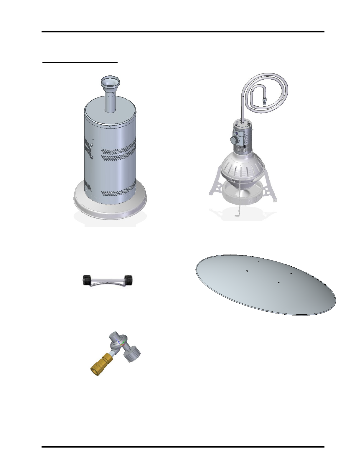
Installation Instructions
Shipping Crate Contents
Reflector
Wheels
Regulator w/ Quick Connect
Base Body, Base Cover, Pole &
Counterweight
Heater Head Assembly

SeriesGA201M2Page10Sept19/2014
Installation Instructions
Hardware Kits:
Contents:
Bags1,2,and3willbetapedtotheinternalpackagingofthebasebody.Bag4isziptiedtoHeadassembly
andBag5willbetapedtothereflector.
Bag1=8‐32x3/8”ButtonSocket(x4)
Bag2=A.3/8”–16S.SNylonLockNuts(x6)B.3/8”S.SWashers(x6)
Bag3=A.1/4”–20x1/2”S.SButtonSock(x6) B.1/4”–20S.SNylonLockNuts(x6)
C.HoldDownBracket(x3)
Bungee=15”BungeeCord
WheelKit=A.WheelAssemblyB.1/4”–20x1/2”S.SButtonSock(x2)
C.1/4”–20S.SNylonLockNuts(x2)
Bag4=#10–24SocketHeadScrew(x3)
Bag5=A.1/4”‐20x1/2”S.SCarriageBolt(x4)B.1/4”WasherS.S(x4)C.1/4”‐20AcornNut(x4)

SeriesGA201M2Page11Sept19/2014
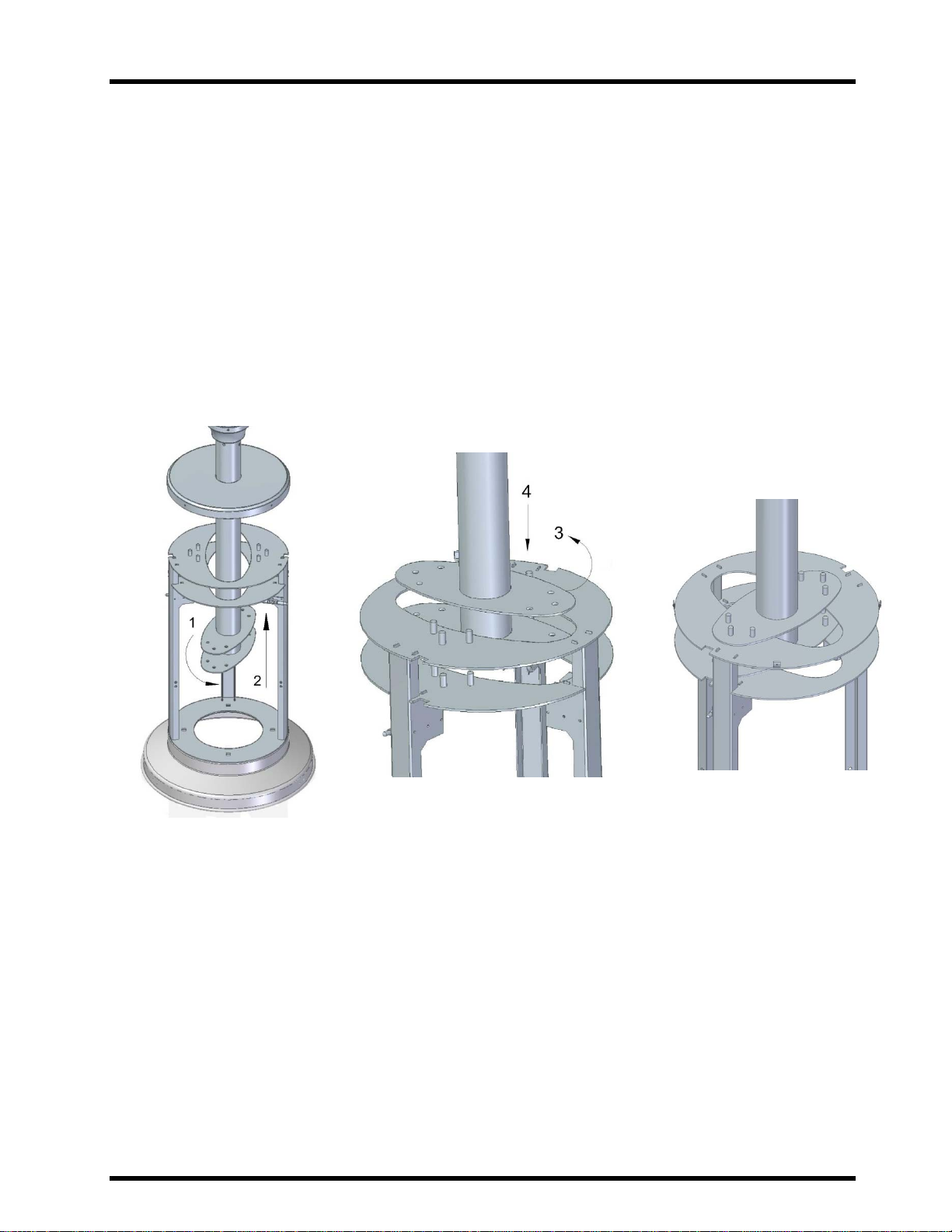
Installation Instructions
Assembly of Outdoor Patio Heater
1. Disassemble shipped parts and separate the hardware packages. Start with the heater base unit and
heater head assembly as shown below.
2. Insert the gas supply hose into the pole neck. The hose will slide down the pole until the head
assembly sits in the pole neck.
3. Rotate the head assembly so the front control knob is facing the coloured sticker on the pole neck as
shown below.
SeriesGA201M2Page12Sept19/2014
Installation Instructions
4. Use the contents in Bag 4 (#10 – 24 Socket Head Screw) to secure the head assembly to the pole
assembly (3 screws). **Remove the colored sticker after securing**
5. Please refer to the illustrations below for clarity in this step. Lift the pole assembly with the head
now attached, upwards. The housing top cover will come with it as there is packing underneath to
hold the top cover in place while you lift the up the pole. Rotate the pole so that the mounting
flanges almost line up with the cutouts on the base plates. Once the top mounting flange is above
the surface, rotate the pole so the holes line up with the treaded bolts. Lower the pole assembly onto
the bolts so they come up through the holes on the mounting flange. Make sure the front of the
heater is facing the evenGLO faceplate on the front of the base.
6. Take the contents out of Bag 2. Slip the washers on the threaded bolts (6). Secure pole assembly by
threading the lock nuts onto the threaded bolts and tighten down with wrench or socket.
7. Carefully take off the packaging holding the housing top cover up the pole. Carefully slide the top
cover down the pole covering the pole-mounting flange and hardware. Use the contents of Bag 1
(#8-32 x 3/8”) to secure the cover to the base body in 4 places.
*Note: Housing Cover not shown below for ease of illustration.*

SeriesGA201M2Page13Sept19/2014
Installation Instructions
8. Open Bag 3. Take the three Hold Down Brackets and locate the mounting holes located at the
bottom of the Main Base as shown below. (only 2 shown below, third is around the back)
9. Insert the bolts supplied in Bag 3 (1/4”-20 x 1/2”) into the Hold Down Bracket and then into the
Main Base mounting holes. Tip heater slightly so you can secure the brackets with the nuts supplied
by reaching underneath the lip. Tighten the nuts flush with inside surface.
10. Locate the Wheel Kit. Open the packaging and take the wheel assembly and the hardware provided
out. Locate the two mounting holes on the Main Base, line up the wheel assembly as shown below.
Insert both bolts into the matching set of mounting holes. Tip the heater slightly to be able to thread
on the Nylon Nuts provided underneath the Main Base. Tighten the nuts until the wheel assembly is
secure.

SeriesGA201M2Page14Sept19/2014
Installation Instructions
11. Locate the reflector and Bag 5. Install the Top Reflector onto the Shield Support Arms of the Burner
using the four (4) 1/4”-20 x 1/2" carriage bolts with nuts provided. Insert the screws up through the
Shield Support Arms and then through the Top Reflector. Secure each bolt with a nut on top of the
Reflector. Make sure to remove (or peel off) the plastic covering on the reflector before assembly.
Warning:
This heater is equipped with a tilt / tip switch for your safety. This heater will shut the gas
valve if it is tipped or tilted.
This heater will not operate at an inclined position. Ensure the heater is in the upright
position, and should not be positioned on an incline.
Your Patio heater is now assembled and is ready to connect to your LP-Gas Supply Cylinder.

SeriesGA201M2Page15Sept19/2014
Installation Instructions
Connecting the LP-Gas Supply
1. Lift the Main Housing Cover up by the handles until the bottom lip is clear of the 3 spring latchs as
shown below.
2. Secure the LP-Gas Cylinder to the Base using the Bungee cord. Hook one side of the Bungge to the
mounting holes on either the right side of left as shown below. Make sure the LP-Gas cylinder is in the
upright position. Feed Bungee through the handle of the LP cylinder, then hook the Bungge on the other set
of securing holes.

SeriesGA201M2Page16Sept19/2014
Installation Instructions
3. Locate the regulator assembly. Look over the assembly to make sure no damage has occurred during
shipping of handling. Attach the regulator assembly to the male quick connect on the fuel supply hose as
shown below.
4. Secure the Gas Hose Regulator onto the LP-Gas Cylinder valve by turning the Regulator clockwise until
tight. Push the 3 spring latches that are holding the Main Housing Cover in place inwards, one hand holding
the bottom lip of the Main Housing Cover and one pushing the latches one at a time. Be careful of the
bottom edge of the Main Housing as it is sharp.
Before using the patio heater:
Perform a leak test to make sure Regulator connection does not have leaks..
Move Heater to desired location.
Secure the Base Body to the floor.

SeriesGA201M2Page17Sept19/2014
Installation Instructions
Position / Move the Heater
1. Ensure the LP-Gas Cylinder is turned OFF, secured and disconnected from the Gas Hose prior to
moving the Heater.
2. Ensure Wheels are properly connected to the Base Body. (Refer to Installation Step 10.)
3. Move the Heater by handling ONLY the Pole or the Base Body. It may take two people to
manoeuvre the Heater safely depending on the size / strength of the person(s).
4. Tip the Heater backwards at an angle to / overtop of the wheels until Base no longer touches the
ground. Wheel / roll Heater to the desired new location and return Base to ground. Ensure Heater
is on level ground and stable in new location.
5. If the Heater is going to be operated at the new location, the “Testing / Commissioning
6. ” procedure must be completed
.

SeriesGA201M2Page18Sept19/2014
Installation Instructions
Secure the Heater
1. Ensure that the Hold Down Brackets are properly installed as described in Installation Step 8.
2. The type of Foundation Fastener required depends on the type of Floor / Ground that the Heater is
located on. Prepare the Floor / Ground as detailed in Table A at all three bracket locations. (Ensure
that alignment with the connecting hole(s) of the Base Bracket is maintained.)
Table A: Methods for Securing Heater to Floor / Ground
Floor / Ground
Type Foundation Fastener
Type & Size Mounting MethodSummary Floor / Ground
Preparation
Concrete
Concrete Anchor
Ø5/16" x 2 1/2"
Place Anchors into pilot holes
aligned with Base Brackets -
tap / hammerlightly, screw
fastener into anchor
Drill 3 -PilotHoles
Pilot hole drill size:
Concrete = 9/16"
Wood Deck Wood Screw
#10 x1 1/2"
Secure using Wood Screws in
pilot holes aligned with Base
Brackets
Drill 3 -PilotHoles
Pilot hole drill size:
Hardwood =7/64"
Softwood =3/32"

SeriesGA201M2Page19Sept19/2014
Testing / Commissioning
Leak Test Method
Never go over connections looking for leaks with a lighted match, cigarette lighter, or any other
flame.
Perform the Leak Test before initial lighting and when connecting a new LP-Gas Cylinder. A
complete gas tightness check must be performed at the installation on site due to possible miss
handing in shipment or excessive pressure being applied to the heater.
1. Make up a dish of soap and water solution of one part liquid detergent and one part water.
2. Spread the soap and water solution over the hose connections with a spray bottle, a small
paintbrush or a rag.
3. With the heater shut OFF, turn the cylinder valve ON. Check the connections at the LP-Cylinder.
4. Take off the Housing Service Cover (shown below). Check the gas line attachment points to the
valve.
5. Any leaks will result in bubbles forming in the solution. If a leak is detected, shut OFF the cylinder
valve.
6. Repair any leak by tightening leaking parts. (The replacement Gas Hose Assembly shall be as
specified by the manufacturer.)
7. Repeat steps 1, 2, and 3 until no leaks are detected at all hose connection locations as shown below.
If you cannot stop the leaks, shut OFF the supply valve on the LP-Gas Cylinder and disconnect the cylinder
from the heater. Place the heater OUT OF SERVICE and consult a certified service person.

SeriesGA201M2Page20Sept19/2014
Testing / Commissioning
After passing the Leak Test your patio heater is now ready for use.
Caution:
Heater will produce smoke the first time it is lit. This is normal. Make sure NOT to light the heater
in an enclosed area.
Make sure all protective plastic has been removed from all surfaces before lighting.
Other manuals for GA201M2
1
Table of contents
Other EvenGlo Patio Heater manuals


Popular Patio Heater manuals by other brands


Blue Sky Outdoor Living
Blue Sky Outdoor Living WBFP31SQ-GF owner's manual

Italkero
Italkero INFRA Spider User manual and assembly instructions

Sunred
Sunred RD-DARK-15-20-25 manual

Firesense
Firesense FireSense 02411 instruction manual

Sakura
Sakura SEP-27 instruction manual

Lowry
Lowry LTTPTH3 MANUAL & SAFETY INSTRUCTIONS


