EvenGlo GA 301 Manual

__________________________________________________________________________________________________________________
Series GA301 1 LT071 Aug 2021
Installation, Operation and Service Instructions
INFRARED PATIO HEATER
SERIES GA301
Models U, T, H (24 VAC)
Models M, MP (pilot)
DANGER
DANGER
If you smell gas:
1. Shut off gas to heater.
2. Extinguish any open flame.
If odor continues, keep away from the heater and
immediately call your gas supplier or fire department.
Do not store or use gasoline or other flammable
vapors and liquids in the vicinity of this or any other
heater.
A propane Cylinder not connected for use shall not be
stored in the vicinity of this or any other heater.
WARNING
WARNING
Improper installation, adjustment, alteration, service,
or maintenance can cause injury, death or property
damage. Read the installation, operation, and
maintenance instructions thoroughly before installing
or servicing this equipment.
FOR OUTDOOR USE ONLY
The evenGLO® heater has been approved for indoor
use in non-residential applications for natural gas
units ONLY!
IMPORTANT
CALIFORNIA PROPOSITION 65
Please retain these instructions for future reference.
The installer must leave these instructions with the
owner. Only those who are certified to do so should
perform service on these heaters.
This heater, its related accessories and by-product of
operation, contain chemicals known to the State of
California to cause cancer and birth defects or other
reproductive harm. For more information go to
www.P65Warnings.ca.gov.
DANGER CARBON MONOXIDE HAZARD
This heater can produce carbon monoxide which
has no odor.
Using it in an enclosed space can kill you.
Never use this heater in an enclosed space such as
a camper, tent or home.
Canada: 563 Barton St., Stoney Creek, Ontario L8E 5S1
www.irenergy.ca
__________________________________________________________________________________________________________________
Series GA301 2 LT071 Aug 2021
CAUTION - MAINTENANCE INSTRUCTION
1. Keep the heater area clear and free from combustible materials, gasoline and other flammable vapors
and liquids.
2. Do not obstruct the flow of combustion and ventilation air.
3. Visually check burner flames.
4. Clean the heater, including special surfaces, with recommended cleaning agents, if necessary.
Check the maintenance section in this manual for additional instructions.
CAUTION - INSTALLATION
This heater shall be used only in a well-ventilated space and shall not be used in a building, garage or any
other enclosed area.
The heater may be installed with shelter no more inclusive than:
1. With walls on all sides, but with no overhead cover.
2. Within a partial enclosure which includes an overhead cover and no more than two side walls. These
side walls may be parallel, as in a breezeway, or at right angles to each other.
3. Within a partial enclosure which includes an overhead cover and three side walls, as long as 30 percent
or more of the horizontal periphery of the enclosure is permanently open.
SAFETY REQUIREMENTS
•At all times, maintain clearance to combustible materials as further specified in this manual. Failure to do so
can result in serious fire hazard.
•Never operate heaters in atmosphere containing flammable vapours or combustible dusts.
•This heater is equipped with an electronic and automatic ignition device. Do not attempt to light the burner by
hand. Failure to comply can result in a serious fire and personal injury hazard.
•Certain materials, when stored under this heater are subjected to radiant heat can soften, distort or
otherwise be damaged, special care should be taken of plastic materials
•Heater surfaces, other than the obvious flame and emitter surfaces, attain elevated temperatures during
operation. Do not touch the heater head during operation. Everyone should be alerted to this hazard to avoid
burning.
•Children should be strictly supervised when in the area of this heating heater. Playing or running around the
structure should be strictly forbidden.
•Clothing or other flammable materials should not be hung on or near this heater.
•Any guard or other protective device removed for servicing the heater must be replaced prior to operating
the heater.
•Installation and repair should be done by a qualified service person. The heater should be inspected before
use and at least annually by a qualified service person.
SAFETY REQUIREMENTS
•Never locate the heater directly below electrical lines, gas lines or sprinkler systems.
•Do not locate heater too close to vinyl or plastic wall coverings. These materials may discolour or soften well
before they reach combustible limits.
•The heater requires a minimum clearance from combustible materials. See the Clearance to Combustible
Materials section for specific requirements.
•Always allow room for maintenance purposes.
•The heater aspirates air for combustion. Do not locate heater where there are severe draft conditions or airflow
restrictions to the burner.

__________________________________________________________________________________________________________________
Series GA301 3 LT071 Aug 2021
Contents
CONTENTS ..................................................................................................................................................................... 3
INTRODUCTION.................................................................................................................................................................. 4
I
NSTALLATION
C
O
DE
S..................................................................................................................................................................... 4
GENERAL SPECIFICATIONS.................................................................................................................................................. 5
DIMENSIONAL CHART ........................................................................................................................................................ 6
GA301-U, GA301-T, GA301-M .................................................................................................................................................... 6
GA301-H ..................................................................................................................................................................................... 7
GA301-MP .................................................................................................................................................................................. 8
COMPONENTS ................................................................................................................................................................... 9
GA301-U, GA301-T, GA301-M .................................................................................................................................................... 9
GA301-MP ................................................................................................................................................................................ 10
HARDWARE KITS ........................................................................................................................................................................... 11
CLEARANCE TO COMBUSTIBLE MATERIALS ........................................................................................................................13
LOCATION PLANNING........................................................................................................................................................ 14
OUTDOOR INSTALLATIONS .............................................................................................................................................................. 14
INDOOR INSTALLATIONS (NATURAL GAS MODELS ONLY) ....................................................................................................................... 15
INSTALLATION INSTRUCTIONS
........................................................................................................................................ 16
FLOOR MOUNT MODELS (GA301-U, GA301-T, GA301-M).............................................................................................................. 16
HANGING MODEL (GA301-H)........................................................................................................................................................ 20
PORTABLE MODEL (GA301-MP) .................................................................................................................................................... 25
GAS SUPPLY ...................................................................................................................................................................... 30
ELECTRICAL WIRING .......................................................................................................................................................... 31
INTERNAL WIRING GA301-U, GA301-T, GA301-H.......................................................................................................................... 31
INTERNAL WIRING GA301-M, GA301-MP ..................................................................................................................................... 31
EXTERNAL WIRING OPTIONS GA301-U, GA301-T, GA301-H ............................................................................................................ 32
STARTUP & SHUTDOWN INSTRUCTIONS
......................................................................................................................33
GA301-U, GA301-T, GA301-H ................................................................................................................................................... 33
GA301-M, GA301-MP............................................................................................................................................................... 33
MAINTENANCE & TROUBLESHOOTING
..........................................................................................................................34
MAINTENANCE ............................................................................................................................................................................. 34
CARE AND CLEANING ..................................................................................................................................................................... 35
TROUBLESHOOTING GA301-U, GA301-T, GA301-H........................................................................................................................ 36
TROUBLESHOOTING GA301-M, GA301-MP.................................................................................................................................... 36
REPLACEMENT PARTS ....................................................................................................................................................... 37
GA301-U, GA301-T, GA301-H REPLACEMENT PARTS ..................................................................................................................... 37
GA301-M &GA301-MP REPLACEMENT PARTS............................................................................................................................... 38
WARRANTY
.................................................................................................................................................................... 39

__________________________________________________________________________________________________________________
Series GA301 4 LT071 Aug 2021
INTRODUCTION
IR Energy is a company in the infrared heating industry founded on the principles of product quality and customer
commitment.
Quality commitments are evidenced by superior design, a regard for design detail and an upgrade of materials
wherever justifiable.
Customer commitment is apparent through our ready responses to market demands and a never- ending training
and service support program for and through our distributor network.
IR Energy offers 25 years of experience in specialty infrared equipment design. Series GA301 models are infrared
patio heaters that are easy to install and maintain, which were engineered with significant input from our customers.
They are designed to provide economical operation and trouble-free service for years to come.
Important
These instructions, the layout drawing, local codes and ordinances, and applicable standards such as apply to
gas piping and electrical wiring comprise the basic information needed to complete the installation and must be
thoroughly understood along with general building codes before proceeding.
Only personnel who have been trained and understand all applicable codes should undertake the installation. IR
Representatives are Factory Certified in the service and application of this equipment and can be called upon for
helpful suggestions about installation.
Installation C
o
de
s
Installations must comply with local building codes, or in their absence, the latest edition of the national regulations
and procedures as listed below.
General Installation
and Gas
Codes
Heaters must be installed only for use with the type of gas appearing on the rating plate, and the installation must
conform to the National Fuel Gas Code, ANSI Z223.1/NFPA 54 in the USA and CSA B149.1 and B149.2
Installation Codes in Canada.
This heater is approved for outdoor installation only. Even-GLO has been approved for indoor use in non-residential
applications for Natural Gas ONLY, see Ventilation section. Not for use in residential dwellings, refer to Rating
plate.
Gas Supply Lines
Gas supply pipe sizing must be in accordance with the National Fuel Gas Code, ANSI Z223.1/NFPA 54 in the USA
and CSA B149.1 and B149.2 Installation Codes in Canada.
A 1/8” NPT plugged tap must be installed in the gas line connection immediately upstream of the burner farthest
from the gas supply meter to allow checking of system gas pressure.
Electrical
All heaters must be electrically grounded in accordance with the National Electric Code, ANSI/NFPA 70 in the USA,
and the Canadian Electric Code, CSA C22.1 in Canada, and must comply with all local requirements.

__________________________________________________________________________________________________________________
Series GA301 5 LT071 Aug 2021
GENERAL SPECIFICATIONS
GA301-U, GA301-T, GA301-H
Gas Supply
Inlet Pressure
Natural Gas
Propane
Minimum
6.5" W.C.
11.0” W.C.
Maximum
14.0” W.C.
14.0” W.C.
Manifold Pressure
Natural Gas
Propane
High Fire
5.5" W.C.
9.8” W.C.
Low Fire
4.0" W.C.
7.0” W.C.
Inlet Connection
Natural Gas
Propane
½” Male Quick Connect
3/8” Male Quick Connect
Electrical Supply
24 VAC, 0.8 A
Heater Specifications
Input
Natural Gas
Propane
High Rate
53,000 BTU/h
47,000 BTU/h
Low Rate
46,000 BTU/h
40,000 BTU/h
GA301-M, GA301-MP
Gas Supply
Inlet Pressure
Natural Gas
Propane
Minimum
6.5" W.C.
11.0” W.C.
Maximum
14.0” W.C.
14.0” W.C.
Manifold Pressure
Natural Gas
Propane
High Fire
5.5" W.C.
9.8” W.C.
Inlet Connection
Natural Gas
Propane
½” Male Quick Connect
3/8” Male Quick Connect
Heater Specifications
Input
Natural Gas
Propane
High Rate
53,000 BTU/h
46,000 BTU/h
High Altitude Installation
When installing this heater over 4500 ft. above sea level in Canada, the heater must be properly de-rated and installed
according to local codes. In the absence of local codes, the heater must be de-rated in accordance with the most
recent CSA -B149 code. In the United States for installations over 2000ft above sea level the heater must be installed
in accordance with the Current National Fuel Gas Code, ANSI Z223.1/NFPA 54 (the heater shall be de-rated 4
percent for each 1000 ft of elevation above sea level). High altitude conversion kits are available, contact
manufacturer for more details.
__________________________________________________________________________________________________________________
Series GA301 6 LT071 Aug 2021
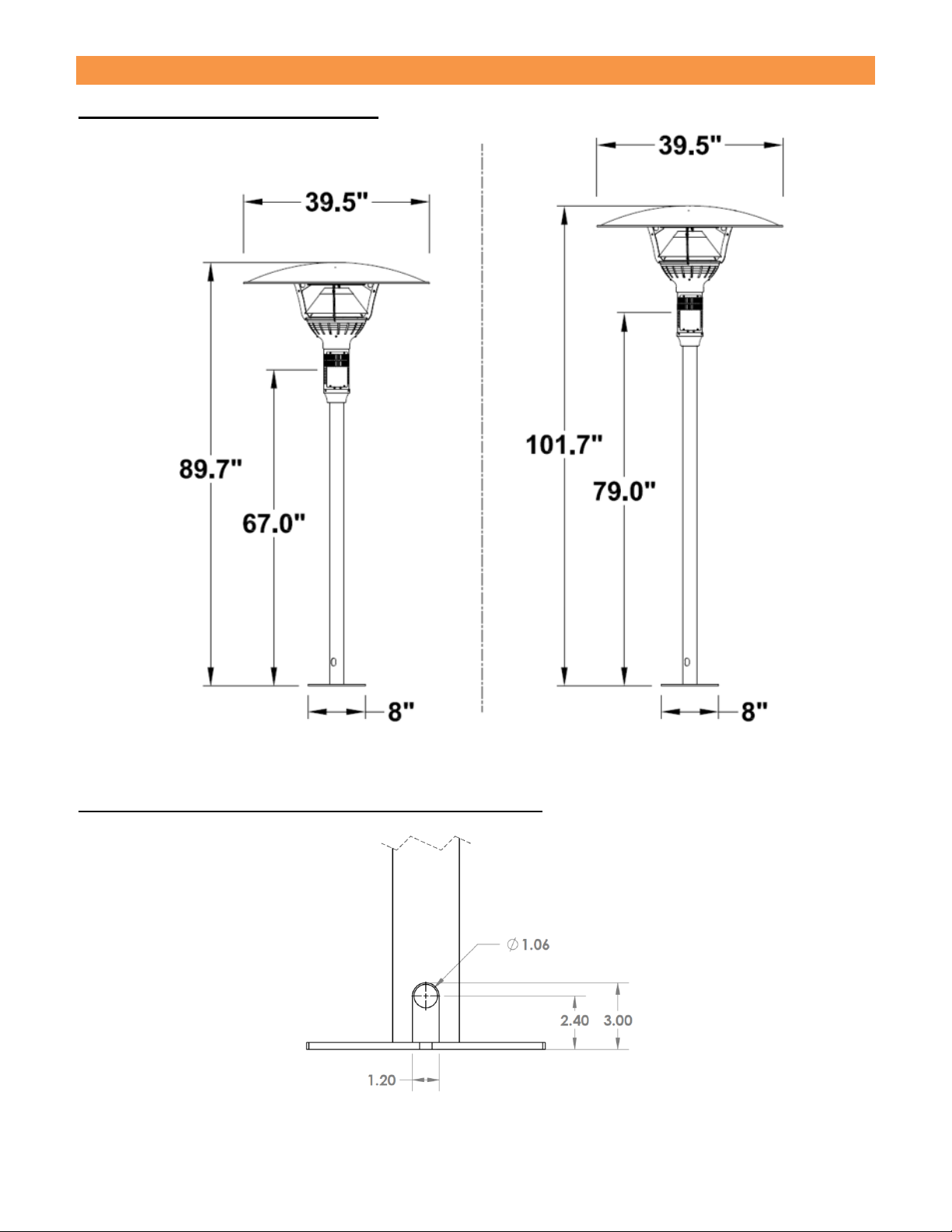
DIMENSIONAL CHART
GA301-U, GA301-T, GA301-M
Figure 1: GA301-U, GA301-M Figure 2: GA301-T
Pole Hole Configuration GA301-U, GA30-T, GA301-M
Figure 3: Pole Hole Configuration (Mounted Heaters)

__________________________________________________________________________________________________________________
Series GA301 7 LT071 Aug 2021
GA301-H
Figure 4: GA301-H Top Dimensions
Figure 5: GA301-H Side Dimensions
__________________________________________________________________________________________________________________
Series GA301 8 LT071 Aug 2021
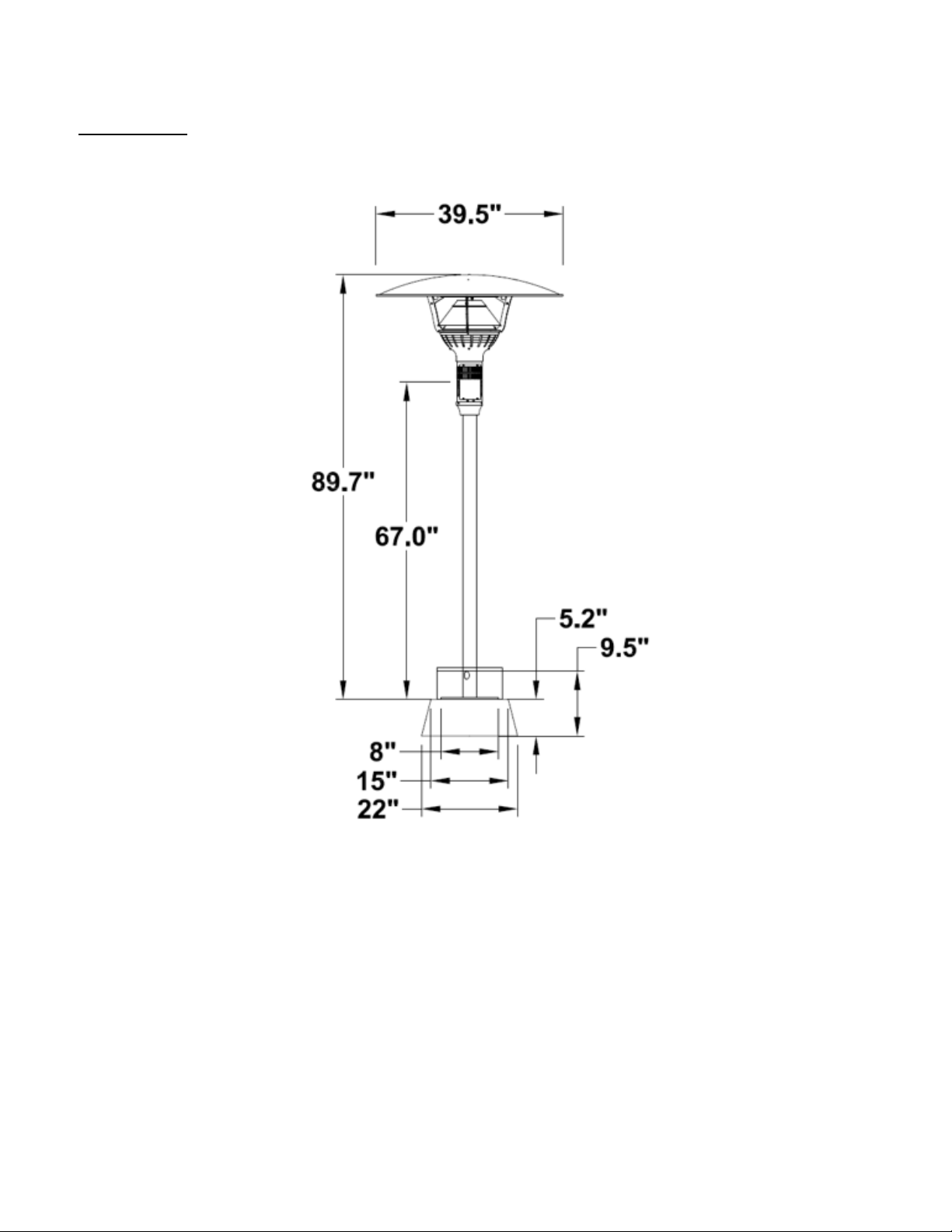
GA301-MP
Figure 6: GA301-MP
__________________________________________________________________________________________________________________
Series GA301 9 LT071 Aug 2021
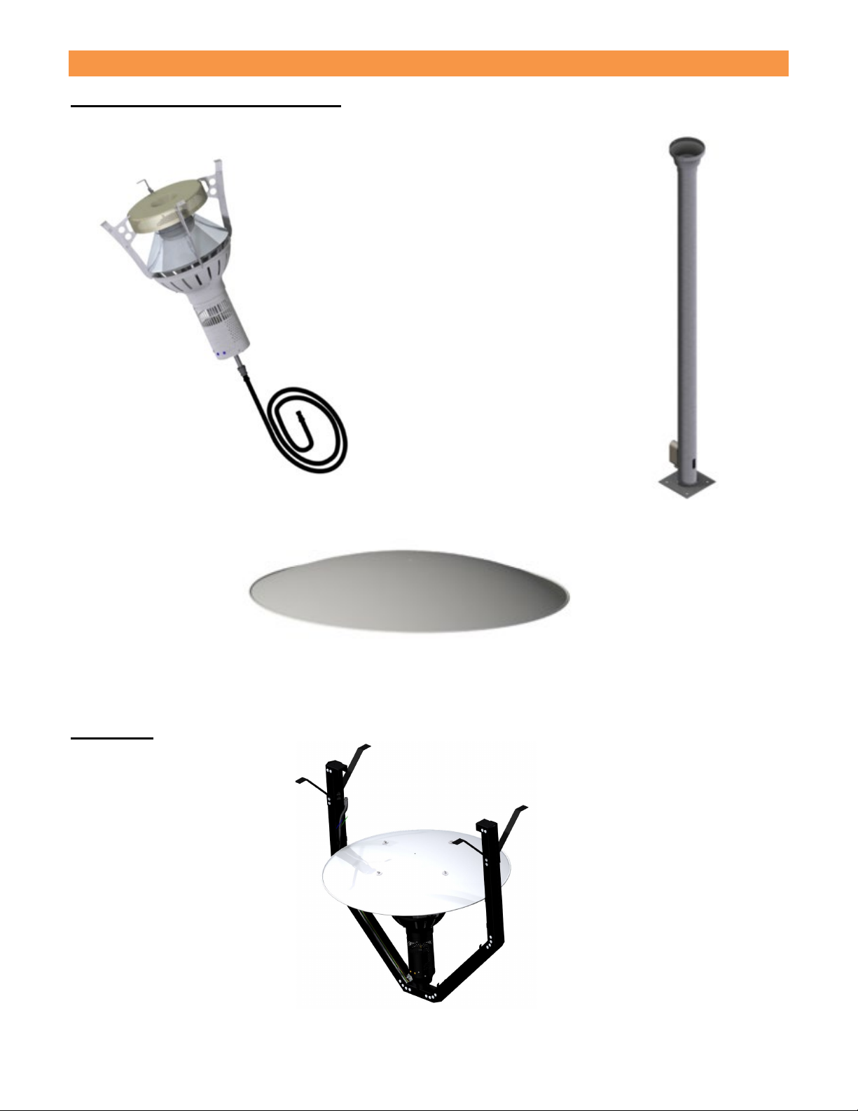
COMPONENTS
GA301-U, GA301-T, GA301-M
GA301-H
Heater Heat
with Gas
Hose
QTY (1)
Top
Reflector
QTY (1)
Fixed
Mounting
Pole
QTY (1)
Heater Base
QTY (1)

__________________________________________________________________________________________________________________
Series GA301 10 LT071 Aug 2021
GA301-MP
Heater
Head with
Gas Hose
QTY (1)
Fixed Mounting Pole
with Detachable Pole
Neck
QTY (1)
Top
Reflector
QTY (1)
Supply Hose
with Quick
Disconnect
QTY (1)
Bottom Base
with Top Cover
and Wheel Kit
QTY (1)
½” QD Socket
Regulator with
Mounting Plate and
Nipple
QTY (1)

__________________________________________________________________________________________________________________
Series GA301 11 LT071 Aug 2021
Hardware Kits
Model GA301-U, GA301-T:
•EH001: Top Reflector to Support Arms
oEH027: 1/4”-20 x 1/2” S.S Carriage Bolt (x4),
oCH143: 1/4” S.S Flat Washer (x4),
oEH028 1/4”-20 S.S Acorn Nut (x4)
•EH021: Pole Package
oEG011: 3/8” x 3/8” FPT x FJIC Swivel Adapter (x1)
oEG013: 3/8” x 90° Bulkhead Elbow (x1)
oEG073: Washer S/S (x1)
Model GA301-H:
•EH001: Top Reflector to Support Arms
oEH027: 1/4”-20 x 1/2” S.S Carriage Bolt (x4),
oCH143: 1/4” S.S Flat Washer (x4),
oEH028 1/4”-20 S.S Acorn Nut (x4)
•EH022: Hanging Package
oCH115: 5/16” – 8 S/S Nut (x17)
oCH116: 5/16” S/S Lock Washer (x17)
oCH140: 8 – 32 S/S Nut (x4)
oCH148: 5/16” – 18 x ¾” S/S Button Socket Bolt (x48)
oCH157: #8 – 32 x 3/8” S/S Screw (x4)
oEG012: 3/8” x 3/8” MJIC x MPT 90° Elbow (x1)
oEH013: #8-18x1/2" S/S Screw (x21)
oES121: Middle Mounting Support S/S (x2)
oES122: Gusset Plate S/S (x8)
oES123: Reflector Stabilizer Bracket S/S (x2)

__________________________________________________________________________________________________________________
Series GA301 12 LT071 Aug 2021
Model GA301-M:
•EH001: Top Reflector to Support Arms
oEH027: 1/4”-20 x 1/2” S.S Carriage Bolt (x4),
oCH143: 1/4” S.S Flat Washer (x4),
oEH028 1/4”-20 S.S Acorn Nut (x4)
•EH085: Heater Head to Pole Neck
oEH041: #10 – 24 S/S Button Socket Cap Screw (x4)
oEH063: 1/8” Allen Key (x1)
•EH087: Pole Neck to Pole
oEH070: 5/16” – 18 x ½” 18 – 8 S/S Button Socket Cap Screw (x)
oEH081: 5/16” S/S Internal Lock Washer (x4)
oEH072: 5/16” – 18 Brass Nylon Insert Lock Nut (x4)
oEH088: 5/16” Allen Key (x1)
Model GA301-MP:
•EH001: Top Reflector to Support Arms
oEH027: 1/4”-20 x 1/2” S.S Carriage Bolt (x4),
oCH143: 1/4” S.S Flat Washer (x4),
oEH028 1/4”-20 S.S Acorn Nut (x4)
•EH084: Housing Top Cover to Base Housing
oEH042: 8 – 32 x 3/8” 18 – 8 S/S Button Socket Cap Screw (x4)
oEH062: 3/32” Allen Key (x1)
•EH085: Heater Head to Pole Neck
oEH041: #10 – 24 S/S Button Socket Cap Screw (x4)
oEH063: 1/8” Allen Key (x1)
•EH086: Pole Flange to Bottom Base
oEH057: 3/8” – 16 S/S Nylon Insert Screw Lock Nut (x4)
oEH056: 8/8” S/S Flat Washer (x4)
•EH087: Pole Neck to Pole
oEH070: 5/16” – 18 x ½” 18 – 8 S/S Button Socket Cap Screw (x)
oEH081: 5/16” S/S Internal Lock Washer (x4)
oEH072: 5/16” – 18 Brass Nylon Insert Lock Nut (x4)
oEH088: 5/16” Allen Key (x1)
Hose Kits (Model GA301-MP):
•EG065: 12’ Hose Kit
oEG052: NG Regulator (x1)
oEG059: ½” Brass Socket (x1)
oEG061: ½” Brass Close Nipple (x1)
oES216: Regulator Mounting Bracket (x1)
oCH122: 8-32 x 3/8” S/S Screw (x2)
oEG062: ½:” x 12’ Supply Hose (x1)
•EG066:15’ Hose Kit
oEG052: NG Regulator (x1)
oEG059: ½” Brass Socket (x1)
oEG061: ½” Brass Close Nipple (x1)
oES216: Regulator Mounting Bracket (x1)
oCH122: 8-32 x 3/8” S/S Screw (x2)
oEG058: ½” x 15’ Supply Hose (x1)

__________________________________________________________________________________________________________________
Series GA301 13 LT071 Aug 2021
CLEARANCE TO COMBUSTIBLE MATERIALS
The following clearance data is based on a maximum limit of 90°F (50°C) plus ambient temperature. Note with an
ambient temperature of 70°F the surface temperatures at the clearance distances listed below could reach 160°F.
Care should be taken with placement of plastic or vinyl in the proximity of the heater as they tend to distort and soften
at these temperatures.
Combustible materials are considered to be wood, compressed paper, plant fibres, plastic, Plexiglas or other
materials capable of being ignited and burned. Such materials shall be considered combustible even through flame-
proofed, fire-retardant treated or plastered.
Additional clearance may be required for glass, painted surfaces and other materials which may be damaged by
radiant or convection heat.
NOTE: Some materials deteriorate or soften at sustained temperatures below 160°F.
Consult material manufacturer for recommendations
The Installer is responsible to ensure that building materials with a low heat tolerance which may degrade
at higher temperatures are protected to prevent degradation.
Figure 7: Clearance Dimensions
TOP
SIDE
BELOW
ALL MODELS
18”
22”
33”

__________________________________________________________________________________________________________________
Series GA301 14 LT071 Aug 2021
LOCATION PLANNING
WARNING
This heater is NOT approved for any indoor Residential application.
If in doubt of your application consult with your local fire marshal or gas authority having jurisdiction.
A Residential Dwelling is a housekeeping unit used or intended to be used as a
domicile by one or more
persons, containing cooking, eating, living, sleeping, and/or sanitary facilities. A Residential Dwelling
does not include an attached and detached garage, workshop or outdoors.
Safety Requirements
1. Never locate the heater directly below electrical lines, gas lines or sprinkler systems.
NOTE: Sprinkler head heat fuse link performance may alter with age.
2. Do not locate heater too close to vinyl or plastic wall coverings. These materials may discolour or soften well
before they reach combustible limits.
3. The heater requires a minimum clearance from of combustible materials. See the Specifications / Details
4. Clearance to Combustible Materials information found in the Specifications / Details section.
5. Always allow room for removal of the Top Reflector and Burner head for maintenance purposes.
6. The heater aspirates (needs) air for combustion. Do not locate heater where there are severe draft conditions
or airflow restrictions to the Burner head of the heater.
Layout Considerations
One Even-GLO heater, at high fire and in windless conditions, has a comfort radius of about twelve feet (24
ft. circle).
A series of heaters providing area heat should be placed about 14-20 feet apart.
Wind protection has an important influence on the body’s ability to retain radiant heat. Use natural or newly built wind
barriers where possible, such as existing buildings, shrubbery or tree lines and fences.
Outdoor Installations
The Heater may be installed with shelter no more inclusive than:
1. With walls on all sides, but with no overhead cover.
2. Within a partial enclosure which includes an overhead cover and no more than two side walls. These side
walls may be parallel, as in a breezeway, or at right angles to each other.
3. Within a partial enclosure, which includes an overhead cover and three side walls, as long as 30 percent, or
more, of the horizontal periphery of the enclosure is permanently open.
A patio that has been almost entirely closed in with a roof and windbreak walls or a tent may be considered
an indoor location in some code authorities. Refer to the Natural Fuel Gas Code, ANSI Z.223.1 (NFPA 54) in
the US and CSA B149.1 and B149.2 Installation Codes in Canada.

__________________________________________________________________________________________________________________
Series GA301 15 LT071 Aug 2021
Indoor Installations (Natural Gas models only)
The Even-GLO heater has been approved for indoor use in non-residential applications (Natural Gas Models
ONLY).
Venting of the flue gases is accomplished by means of an interlocked fan. Refer to the Natural Fuel Gas Code,
ANSI Z.223.1 (NFPA 54) in the US and CSA B149.1 and B149.2 Installation Codes in Canada.
Requirements for combustion air supply and dilution air vary by jurisdiction, building type and specific installation
details. See local codes for guidance.
In general, where heaters are installed without direct outside combustion air, fresh air ventilation must be provided
to building space (3 cfm per 1000 BTU/Hr in Canada, 4 cfm per 1000 BTU/Hr in the USA). Verify applicable local
codes in the USA as requirements change by jurisdiction.

__________________________________________________________________________________________________________________
Series GA301 16 LT071 Aug 2021
Installation Instructions
Floor Mount Models (GA301-U, GA301-T, GA301-M)
Mounting Plate Hole Pattern
(Full size)

__________________________________________________________________________________________________________________
Series GA301 17 LT071 Aug 2021
1. Mount pole base onto a concrete floor or cast concrete with a minimum below grade depth of 12” and
having a 12” diameter. If forming concrete, cast in place appropriate passage for gas and control wires.
Use minimum 3/8” x 5” 90° lag bolts or equivalent to mount heater base to the concrete base. The pole
base could also be mounted on wood decks with 3/8” bolts and lock washers on the underside of the deck.
Periodically check for tightness when mounted to a wood deck.
Figure 8: Pole Base Placement
2. Arrange the burner head such that the wires and gas hose are arranged as illustrated. Feed a pull wire
through the pole to assist in pulling the three power wires into the pole and through the junction box. Firmly
tape the pull wire to the power wires. Lower the assembly into place while pulling the wires. Two people
may be necessary for this operation.
Figure 9: Wire and Hose Assembly
__________________________________________________________________________________________________________________
Series GA301 18 LT071 Aug 2021
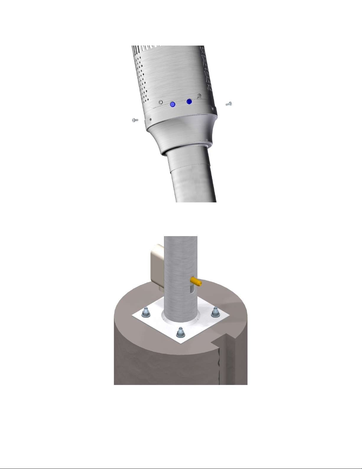
3. Secure burner head to pole with four #10 screws provided.
Figure 10: Burner Head Installation
4. Push the gas connection into the slot by slightly pushing on the gas line through the electrical box. The gas
fitting should be positioned as illustrated below.
Figure 11: Gas Connection Position
__________________________________________________________________________________________________________________
Series GA301 19 LT071 Aug 2021
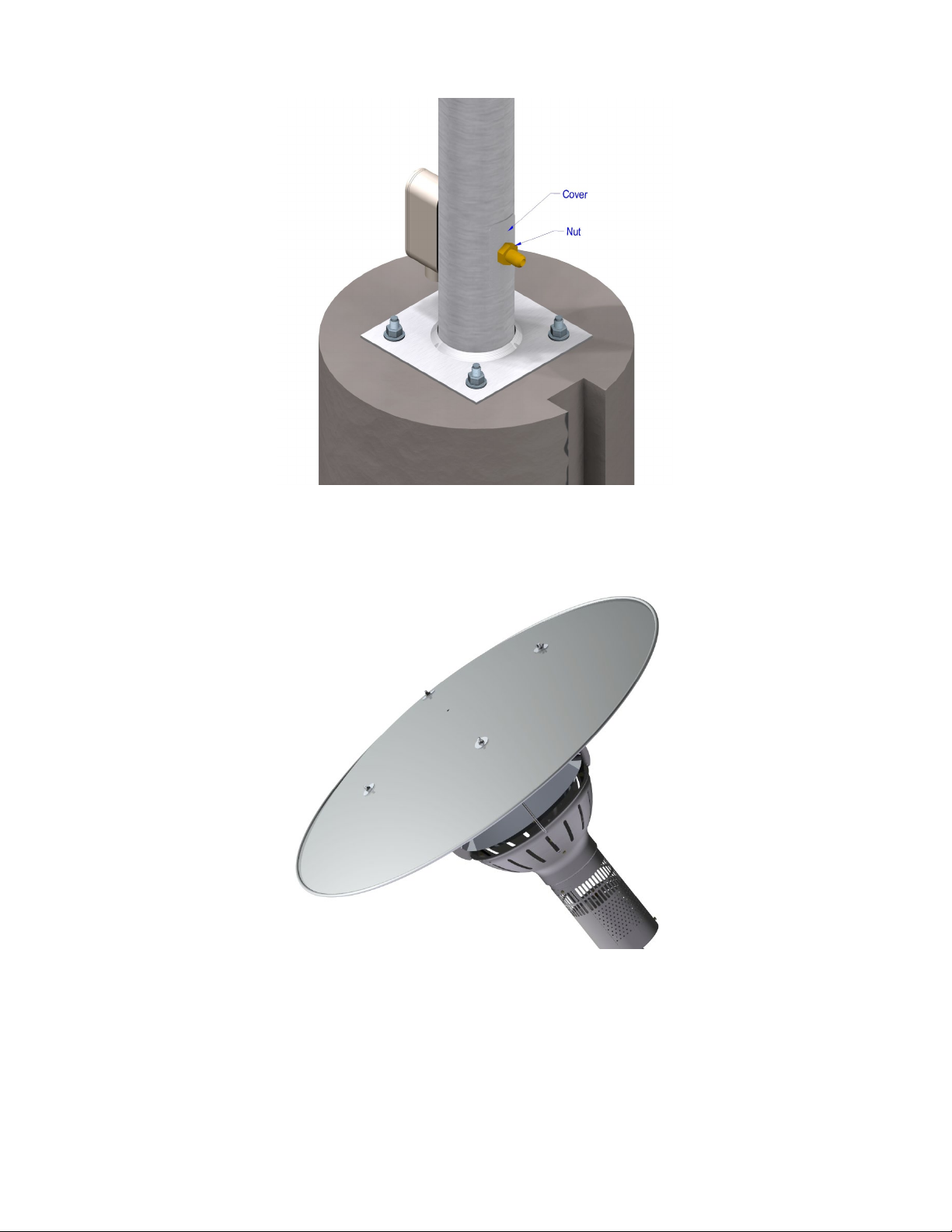
5. Place gas connection cover onto the fitting and install the nut to fasten the cover assuring the nut is
properly seated. See below.
Figure 12: Gas Connection
6. Install reflector using the four carriage bolts, nuts and washers provided.
Figure 13: Reflector Installation
Figure 4
__________________________________________________________________________________________________________________
Series GA301 20 LT071 Aug 2021
Hanging Model (GA301-H)
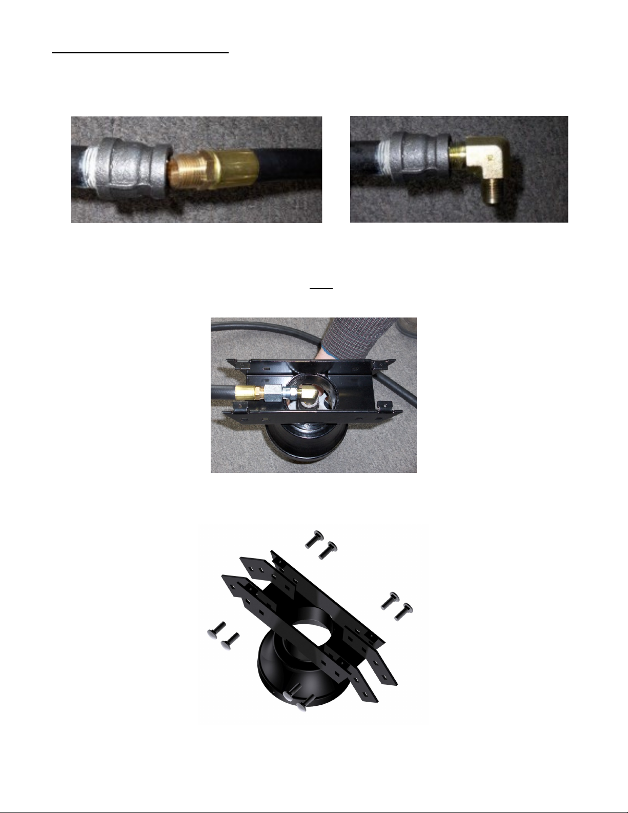
1. Disconnect gas hose from reducing coupling. Connect flared elbow to reducing couple and align elbow to
point at a right angle to the heater door opening.
Figure 14: Gas Hose Connections
2. After inserting the heater assembly into the frame base, connect the swivel fitting on the opposite end of
the gas hose to the flared elbow. See Figure 15. Note: All gas connections must be done according to
local and national codes. Also, all new connections must be leak tested.
Figure 15: Insert Heater Assembly into Frame Base
3. Assemble 4 gusset plates to the base as illustrated. Use 5/16” carriage bolts with washers and nuts.
Figure 16: Gusset Plate Assembly
This manual suits for next models
5
Table of contents
Other EvenGlo Patio Heater manuals


Popular Patio Heater manuals by other brands

empasa
empasa Classic light user manual

Four Seasons Courtyard
Four Seasons Courtyard HYFP2001-1 owner's manual

Pinnacle AGRI
Pinnacle AGRI FIRESTORM Phoenix Instruction leaflet

Martin
Martin 132/PH01G User installation and operation guide

Blumfeldt
Blumfeldt 10028637 manual

Heatmaxx
Heatmaxx SRPH98 instruction manual


