Everbilt CX1500EVB User manual

THANK YOU
We appreciate the trust and condence you have placed in Everbilt through the purchase of this ventilator fan. We strive to
continually create quality products designed to enhance your home. Visit us online to see our full line of products available for your
home improvement needs. Thank you for choosing Everbilt!
USE AND CARE GUIDE
GABLE MOUNTED VENTILATOR FAN
Questions, problems, missing parts? Before returning to the store,
call Everbilt Customer Service
8 a.m. - 7 p.m., EST, Monday - Friday, 9 a.m. - 6 p.m., EST, Saturday
1-877-527-0313
HOMEDEPOT.COM
Item #1005 443 074
Model #CX1500EVB

2
Table of Contents
Safety Information ..................................2
Warranty ..........................................3
Tools Required ....................................4
Package Contents .................................4
Pre-Installation.....................................4
Installation — Wall-Vent Mounted .....................5
Installation — Triangular Gable Vents...................6
Installation – Thermostat.............................8
Operation. . . . . . . . . . . . . . . . . . . . . . . . . . . . . . . . . . . . . . . . . . 8
Maintenance .......................................9
Care and Cleaning ..................................9
Troubleshooting ....................................9
Safety Information
Read all warnings and instructions before beginning to install this fan.
FAILURE TO FOLLOW THESE INSTRUCTIONS COULD RESULT IN INJURY OR EVEN DEATH.
WARNING: Do not attempt to use this fan with any solid-state
speed control device.
WARNING: Use this unit only in the manner intended by
the manufacturer. If you have any questions, contact the
manufacturer.
WARNING: Before servicing or cleaning this unit, switch
the power off at the service panel and lock out to prevent the
power from being switched on accidentally. When service
disconnecting means cannot be locked, securely fasten a
prominent warning tag to the service panel.
WARNING: Installation work and electrical wiring must
be performed by a qualied person in accordance with
all applicable codes and standards, including re-rated
construction.
WARNING: When cutting or drilling into a wall or ceiling, do
not damage the electrical wiring and other hidden utilities.
WARNING: The combustion airow needed for safe operation
of fuel-burning equipment may be affected by this unit’s
operation. Follow the heating equipment manufacturer’s
guidelines and safety standards, such as those published by
the National Fire and Protection Association (NFPA) and the
American Society for Heating, Refrigeration and Air-conditioning
Engineers (ASHRAE); and the local code authorities.
CAUTION: This unit has an unguarded propeller. Do not
use it in locations readily accessible to people or animals.
CAUTION: Mount the unit with the lowest moving parts at
least 8 feet above oor level.
CAUTION: For general ventilating use only. Do not use to
exhaust hazardous or explosive materials and vapors.
CAUTION: Carbon monoxide is an odorless, colorless gas
that can kill. It may be drawn into the house by operating
this fan if your fuel-burning equipment is not properly
maintained, or if you lack adequate attic intake vents.
3 HOMEDEPOT.COM
Please contact 1-877-527-0313 for further assistance.
Warranty
The manufacturer extends this warranty to the original retail purchaser of its model or, if this unit is purchased and installed by a new home
builder, then to the original owner of the home. No subsequent purchaser of the unit or of a home in which it is installed is entitled to any of
the benets of this warranty.
This product is warranted against defects in materials and workmanship for a period of two (2) years from the date of original retail
purchase. No other components or parts are warranted. There is no warranty for defects caused by abuse, faulty installation, or the like.
Repairs or replacement parts supplied under this warranty are warranted only for the period of this warranty; that is, two (2) years from the
date of the original retail purchase of the unit.
In the event of a defect or malfunction, we will replace or repair the defective part or component only and return the new or repaired part to
your freight prepaid. You must bear all other expenses incurred in obtaining repairs, including labor required for eld repair or replacement
and the cost of shipping the defective part of component to use. You must also bear the cost of repair to or replacement of any part of
component and the shipping charges incurred for the repair or replacement and return to you any part of component not covered by this
warranty, including parts of components damaged by you.
The company reserves the right to demand and receive written evidence of the date of purchase before undertaking to perform its
obligations under this warranty. You should, therefore, retain your sales slip and attach a copy of it to the warranty claim.
There is no informal dispute setting mechanism available in the event of a controversy involving this warranty.
Any and all implied warranties which may exist terminate upon the expiration of this written warranty, two (2) years from the date of the
original retail purchase. Some states do not allow limitations on how long an implied warranty lasts, so this limitation may not apply to you.
The manufacturer is not liable to you for incidental or consequential damages arising out of a defect or malfunction of a unit of its
installation or out of any alleged breach of this warranty. Some states do not allow the exclusion or limitation of incidental or consequential
damages, so this limitation may not apply to you.
This warranty gives you specic legal rights and you may also have other rights which may vary from state to state.
Contact the Customer Service Team at 1-877-527-0313 or visit www.HomeDepot.com.

4
Pre-Installation
TOOLS REQUIRED
Phillips
screwdriver
Flathead
screwdriver
Wood
screws
Speed
square
14-gauge
electric
wire
Saw
Pencil Straight
edge
Measuring
tape
Portable
electric
drill
Personal
protective
equipment
PACKAGE CONTENTS
A
B
C
D
E
Part Description
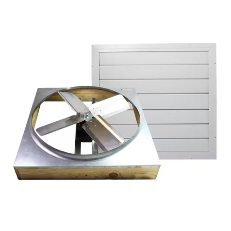
A Gable mount fan
B Thermostat assembly
C Mounting bracket
Part Description
D Mounting bracket nut
E Mounting bracket bolt

5 HOMEDEPOT.COM
Please contact 1-877-527-0313 for further assistance.
Installation — Wall-Vent Mounted
This gable-mounted unit is designed for attics of average size and operates most efciently when air intakes are located around the
eaves. Alternatively, air intake may be from opposing gable vents, but never from roof or ridge vents. At least 600 sq. in. of net free
air intake is required per unit for safe and efcient operation. The motor operates on 120 V, 60 Hz, AC current. See the motor label for
amperage.
This unit may be mounted behind any static wall vent, or behind models VX1818 or CX2121 automatic shutters.
TIP: Much of the preparation, thermostat wiring, testing, and mounting to the frame can be
done before nal installation in the attic.
1 Framing the opening
□For new installation or installation behind existing louvers,
using 2 x 4 studs, frame an opening at least 18 ¼-in.
square (depending on stud spacing) on center, on the attic
side of the gable.
18.25" H
18.25" H
2 Covering the opening and cutting
thehole
□Cover the opening with a square piece of plywood,
paneling, or sheetrock, at least 21 ¼-in. square (depending
on stud spacing).
□Cut a 15-in. diameter hole in the center of this panel to
allow the shroud of the fan to enter the hole.
IMPORTANT: Block off any remaining open vent area
in the gable.

6
Installation – Wall-Vent Mounted (continued)
3 Installing the shutter
□With the mounting nuts (D) and mounting bolts (E), secure
the 4 mounting brackets (C) to the shroud and then fasten
the unit to the frame.
NOTE: Mounting the long side of the L brackets with the
long side to the shroud may better t your installation and
help reduce vibration.
□Seal off any gaps around the fan to allow the fan to
function at maximum efciency.
C
D
E
Installation — Triangular Gable Vents
This gable-mounted unit is designed for attics of average size and operates most efciently when air intakes are located around the
eaves. Alternatively, air intake may be from opposing gable vents, but never from roof or ridge vents. At least 600 sq. in. of net free
air intake is required per unit for safe and efcient operation. The motor operates on 120 V, 60 Hz, AC current. See the motor label for
amperage.
This unit may be mounted behind any static wall vent, or behind models VX1818 or CX2121 automatic shutters.
TIP: Much of the preparation, thermostat wiring, testing, and mounting to the frame can be
done before nal installation in the attic.

7 HOMEDEPOT.COM
Please contact 1-877-527-0313 for further assistance.
Installation – Triangular Gable Vents (continued)
1 Framing the opening
□For new installation or installation behind existing louvers,
using 2 x 4 studs, frame an opening at least 18 ¼-in square
(depending on stud spacing) on center, on the attic side of
the gable.
2 Covering the opening and cutting
thehole
□Cover the opening with a square piece of plywood,
paneling, or sheetrock, at least 21 ¼-in square (depending
on stud spacing).
□Cut a 15-in. diameter hole in the center of this panel to
allow the shroud of the fan to enter the hole.
IMPORTANT: Block off any remaining open vent area
in the gable.
3 Installing the shutter
□With the mounting nuts (D) and mounting bolts (E), secure
the 4 mounting brackets (C) to the shroud and then fasten
the unit to the frame.
NOTE: Mounting the long side of the L brackets with the
long side to the shroud may better t your installation and
help reduce vibration.
□Seal off any gaps around the fan to allow the fan to
function at maximum efciency.
D
E
C

8
Installation – Thermostat
WARNING: Turn off the electrical current to the unit before attempting any service work. If you are unfamiliar
with methods of installing electrical wiring, secure the services of a qualied electrician. All electrical
connections must be in accordance with local codes and ordinances, and/or with national electrical codes.
□Disconnect the power to the unit.
□Remove the thermostat cover.
□Remove the box.
□Mount the new box to the rafter using wood screws to attach
them.
□Connect one black wire from the thermostat to the black wire
of the incoming power supply.
□Connect the other black wire from the thermostat to the black
motor wire.
□Connect the white wire from the power supply to the white
motor wire.
□Attach the ground from the incoming power supply to the
ground screw (1).
1
Power
Supply
To
Motor
WARNING: Before wiring the thermostat, turn the power
off at the breaker to avoid electrocution.
WARNING: Ensure that you conform to all local electrical
codes and regulations.
WARNING: Remove the cover from the thermostat box and
use screws to attach the mounting plate to a stud.
WARNING: When installing the thermostat box, use screws
to attach it to the stud to prevent damage to the control.
WARNING: Leave the back side of the control unobstructed
to allow free air circulation behind the box.
WARNING: Wire the unit to the incoming power supply
according to the diagram below.
WARNING: The thermostat is adjustable. Recommended
setting is 90-110 degrees F depending on local temperatures.
WARNING: The fan will run as long as the attic
temperature remains above the set temperature.
Operation
Ensure adequate air intake (4.5 sq. ft.) is available prior to
operation. Set the thermostat to the desired attic temperature and
ensure sufcient power is supplied to the unit.
WARNING: Keep away from and be aware of the
moving fan blade.
Use a athead screwdriver to adjust the temperature setting to the
desired attic temperature.

9 HOMEDEPOT.COM
Please contact 1-877-527-0313 for further assistance.
Maintenance
WARNING: Disconnect the power before you perform
any maintenance.
□Check the electrical connections annually.
□Ensure that the housing is unobstructed and free of debris to allow proper air ow.
□Ensure that the gable vent shutters are operating properly.
Care and Cleaning
WARNING: Disconnect the power before you perform
any cleaning.
□Wipe the unit down with a damp cloth or rag.
□Do not use corrosive or harsh chemicals to clean.
Troubleshooting
Problem Solution
The fan will not turn on. □Ensure that there is a proper electrical connection.
□Check the breaker in the main fuse panel.
□Adjust the temperature setting on the thermostat.
The fan will not turn off. □Ensure that there is a proper electrical connection.
□Raise the temperature setting on the thermostat.
There is a loud noise coming from
the unit.
□Ensure that there are no obstructions or debris caught in the housing.
□Ensure that the unit is securely fastened to its mounting surface.
□If possible, identify whether the noise is coming from a motor. If so, the problem is probably a
bearing issue.
□Check for any loose screws or hardware.
□Ensure that the gable vent is unobstructed and that air is owing through it.

Questions, problems, missing parts? Before returning to the store,
call Everbilt Customer Service
8 a.m. - 7 p.m., EST, Monday-Friday, 9 a.m. - 6 p.m., EST, Saturday
1-877-527-0313
HOMEDEPOT.COM
Retain this manual for future use.
This manual suits for next models
1
Table of contents
Other Everbilt Fan manuals

Everbilt
Everbilt TD48PGKHD6 User manual

Everbilt
Everbilt TD48PMKHD6 User manual

Everbilt
Everbilt SEVHD User manual

Everbilt
Everbilt CX242DDWTEVB User manual

Everbilt
Everbilt EZFXHD User manual

Everbilt
Everbilt TD48PMKHD6 User manual

Everbilt
Everbilt EZCNHD User manual

Everbilt
Everbilt TDIDVKHD6 User manual

Everbilt
Everbilt PCLT4WHD User manual
Popular Fan manuals by other brands

Craftmade
Craftmade Monaghan MGN52AO installation guide

Bimar
Bimar VP42T Instruction booklet

Kichler Lighting
Kichler Lighting Arkwet Weather+ instruction manual

Sunbeam
Sunbeam SBF2012-CN owner's guide

CristalRecord
CristalRecord Slice instruction manual

Hunter
Hunter Anfield 53265 Owner's guide and installation manual