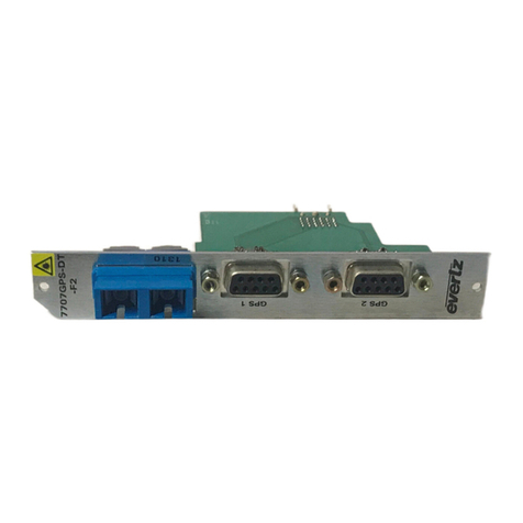
evertz 7700 Series User manual

7700 MultiFrame Manual
7705ET Ethernet Fiber Transceiver
Revision 1.4
TABLE OF CONTENTS
1. OVERVIEW.......................................................................................................................................... 1
2. INSTALLATION................................................................................................................................... 3
2.1. ETHERNET CONNECTIONS..................................................................................................... 3
2.2. OPTICAL CONNECTIONS......................................................................................................... 5
2.2.1. Single Fiber version (7705ET)......................................................................................... 5
2.2.2. Dual Fiber Version (7705ET-F2)..................................................................................... 5
2.3. CARE AND HANDLING OF OPTICAL FIBER........................................................................... 5
2.3.1. Safety.............................................................................................................................. 5
2.3.2. Handling and Connecting Fibers..................................................................................... 6
3. SPECIFICATIONS............................................................................................................................... 7
3.1. ETHERNET INPUT/OUTPUT..................................................................................................... 7
3.2. OPTICAL INPUT/OUTPUT......................................................................................................... 7
3.3. ELECTRICAL ............................................................................................................................. 7
3.4. PHYSICAL.................................................................................................................................. 7
4. STATUS INDICATORS....................................................................................................................... 8
4.1. MODULE HEALTH LEDS .......................................................................................................... 8
4.2. FIBER LINK LED........................................................................................................................ 8
4.3. CARD EDGE ETHERNET LEDS................................................................................................ 8
4.4. REAR PANEL ETHERNET LEDS.............................................................................................. 9
5. JUMPERS AND USER ADJUSTMENTS.......................................................................................... 10
5.1. SELECTING WHETHER LOCAL FAULTS WILL BE MONITORED
BY THE GLOBAL FRAME STATUS........................................................................................ 10
5.2. CONFIGURING THE MODULE FOR FIRMWARE UPGRADES ............................................. 11
5.3. SELECTING THE CARD ADDRESS (Single Fiber version only) ......................................... 11

7700 MultiFrame Manual
7705ET Ethernet Fiber Transceiver
Revision 1.4
Figures
Figure 1-1: 7705ET Block Diagram.......................................................................................................................2
Figure 1-2: 7705ET-F2 Block Diagram.................................................................................................................2
Figure 2-1: 7705ET Rear panels...........................................................................................................................3
Figure 5-1: LED and Jumper Locations..............................................................................................................10
Tables
Table 2-1: Ethernet Connector Pin Definitions and Cable Wiring.........................................................................4

7700 MultiFrame Manual
7705ET Ethernet Fiber Transceiver
Revision 1.4
REVISION HISTORY
REVISION DESCRIPTION DATE
1.0 First release version Nov 01
Drawings and specs updated
1.1 Specifications and drawings updated Jan 02
1.2 Changed model number of 7707ET-FC to 7707ET Jun 02
Updated info on Address Jumper
1.3 Added 8 new CWDM wavelengths Dec 02
1.4 Fixed formatting Nov 08
Information contained in this manual is believed to be accurate and reliable. However, Evertz assumes no responsibility for the use thereof nor for
the rights of third parties, which may be effected in any way by the use thereof. Any representations in this document concerning performance of
Evertz products are for informational use only and are not warranties of future performance, either express or implied. The only warranty offered by
Evertz in relation to this product is the Evertz standard limited warranty, stated in the sales contract or order confirmation form.
Although every attempt has been made to accurately describe the features, installation and operation of this product in this manual, no warranty is
granted nor liability assumed in relation to any errors or omissions unless specifically undertaken in the Evertz sales contract or order confirmation.
Information contained in this manual is periodically updated and changes will be incorporated into subsequent editions. If you encounter an error,
please notify Evertz Customer Service department. Evertz reserves the right, without notice or liability, to make changes in equipment design or
specifications.

7700 MultiFrame Manual
7705ET Ethernet Fiber Transceiver
Revision 1.4
This page left intentionally blank

7700 MultiFrame Manual
7705ET Ethernet Fiber Transceiver
Revision 1.4 7705ET - 1
1. OVERVIEW
The 7705ET Ethernet Fiber Transceiver provides an economical method of transmitting two 10BaseT
Ethernet channels or one 100Base-TX Ethernet channel over optical fiber. The converter is IEEE 802.3
10BASE-T and IEEE 802.3u 100BASE-TX compliant, mediates between a 10/100BASE-TX segment and
supports both full duplex and half-duplex operation. A pair of 7705ET transceivers permits full duplex
communication over a single optical fiber. Diagnostic LEDs provide indication of power, linkage and data
reception.
Features:
•Auto negotiation for 10/100 speeds, half/full duplex modes
•Built in Ethernet switch for complete isolation of each transmission end
•Link status monitoring indicators
•VistaLINK®enabled for remote monitoring and control
•Optical output available in 1310nm, 1550nm and up to sixteen CWDM wavelengths in the 1270nm to
1610nm range
•Supports multi-mode or single-mode fiber
•Fully hot-swappable from front of frame with no fiber or Ethernet channel disconnect required
•SC/PC, ST/PC or FC/PC connector options
Two versions of the 7705ET allow the user to choose the optimal price / performance to suit a particular
application. The “-F2” version is designed to receive and transmit on the same wavelength over two
different fibers and has the lowest insertion loss. This version can operate with Multi-mode (MM) or Single-
mode (SM) fiber. The standard version is designed to receive and transmit on the same wavelength over a
single fiber and can operate with SM fiber only. Each version of the 7705ET is available with a 1310 nm
FP laser output. (See section 3 for specification information):
The following chart shows some typical applications and power budget calculations.
Application Output
Power
Input
Sensitivity
(dBm)
Max
Loss
Budget
Controller
(Side A) Device
(Side B)
Single Fiber, Single Wavelength 1310nm, FP laser -11 -25 14 7705ET13 7705ET13
Dual Fiber, single wavelength 1310 nm, FP laser -8 -28 20 7705ET13-F2 7705ET13-F2

7700 MultiFrame Manual
7705ET Ethernet Fiber Transceiver
7705ET - 2 Revision 1.4
10/100 TX
RJ45 Input
10/100 TX
RJ45 Input
Fiber XCVR Combiner
Optical
In/Out
Ethernet
Switch
Indication
Mode10/100LN/ACT
Fiber Link
10/100 ModeLN/ACT
Figure 1-1: 7705ET Block Diagram
10/100 TX
RJ45 Input
10/100 TX
RJ45 Input
Fiber XCVR
Ethernet
Switch
Indication
Optical
Output
Optical
Input
Mode10/100LN/ACT
Fiber Link
10/100 ModeLN/ACT
Figure 1-2: 7705ET-F2 Block Diagram

7700 MultiFrame Manual
7705ET Ethernet Fiber Transceiver
Revision 1.4 7705ET - 3
2. INSTALLATION
The 7705ET comes with a companion rear plate that has two RJ-45 input connectors and one SC/PC
(shown), ST/PC or FC/PC optical connector. The 7705ET-F2 version comes with a companion rear plate
that has two RJ-45 input connectors and two SC/PC, ST/PC or FC/PC optical connectors. For information
on mounting the rear plate and inserting the module into the frame see section 3 of the 7700FR chapter.
Figure 2-1: 7705ET Rear panels
2.1. ETHERNET CONNECTIONS
The RJ-45 connectors on the rear panel are for connection to network devices (server, workstation, router
switch, etc.) with a 10/100BASE-TX port through a twisted pair cable. While both RJ-45 ports will auto-
negotiate between 10 and 100 Mb/sec, the fiber port runs at only 100 Mb/sec. This means that while both
RJ-45 ports can run at 100 Mb/sec at the same time, packets may be lost if both ports have a high traffic
load. Therefore we recommend that only one RJ-45 port be used if it is to run at 100 Mb/sec.
The 7705ET Ethernet Transceiver is designed for use with 10/100Base-TX twisted pair Ethernet cabling
systems. When connecting for 100Base-TX systems, category 5 UTP cable is required. The maximum
cable run between the Ethernet Fiber Transceiver and the supporting hub is 100 metres. Make the
network connection by plugging one end of the cable into the RJ-45 receptacle of the Ethernet Fiber
Transceiver and the other end into a port of the supporting hub.

7700 MultiFrame Manual
7705ET Ethernet Fiber Transceiver
7705ET - 4 Revision 1.4
When connecting the 7705ET to a hub or switch a “straight through” cable must be used. When
connecting the 7705ET to the Evertz 7700FC VistaLINK®Frame Controller, another 7705ET, or the
network interface card of a computer, a “crossover” cable must be used.
Pin # Name Cable Pair Description
1 TX+ -------1a------ Transmit + Output
2 TX- -------1b----- Transmit – Output
3 RX+ -------2a------ Receive + Input
4 not used
5 not used
6 RX- -------2b------ Receive – Input
7 not used
8 not used
Table 2-1: Ethernet Connector Pin Definitions and Cable Wiring
Devices on the Ethernet network continually monitor the receive data path for activity as a means of
checking that the link is working correctly. When the network is idle, the devices also send a carrier signal
to one another to maintain the link. The 7705ET rear panel is fitted with two LEDs on each RJ-45
connector to monitor the Ethernet connection on each port.
10/100: This Green LED is On when a 100Base-TX link is established. The LED is Off when
a 10Base-T link is established (the LINK LED is On) or if there is no link established
(the LINK LED is Off). This LED should show the same information as the
respective 10/100 LED on the card edge.
LN/ACT: This dual purpose Green LED indicates that the 7705ET has established a valid
link, and whether the 7705ET is sending or receiving data. The LED will be On
when the 7705ET has established a good link, providing a good indication that the
segment is wired correctly. The LED will BLINK when the 7705ET is sending or
receiving data. The LED will be Off if there is no valid connection.

7700 MultiFrame Manual
7705ET Ethernet Fiber Transceiver
Revision 1.4 7705ET - 5
2.2. OPTICAL CONNECTIONS
"The 7705ET modules are designed to work with single-mode or multi-mode optical
fiber depending on the version (FC, F2) ordered.
2.2.1. Single Fiber version (7705ET)
FIBER I/O: There is one SC/PC (shown), ST/PC or FC/PC female connector with the optical
input/output from the 7705ET. This connector should be connected to the matching
connector of another 7705ET module at the destination end with a suitable fiber optic cable.
The 7705ET version receives on wavelengths in the 1270 to 1610nm range, transmits on a
1310 nm wavelength and is designed to work with either single-mode or multi-mode fiber
optic cable.
"
In order to establish a valid link between a pair of single fiber 7705ET modules,
one module must be configured as ‘Address A’, and the other as ‘Address B’.
Selection of the correct address is achieved by setting jumper J6. See section 5.3.
2.2.2. Dual Fiber Version (7705ET-F2)
FIBER IN: There is one SC/PC (shown), ST/PC or FC/PC female connector with the optical input to
the 7705ET-F2. This connector should be connected to the FIBRE OUT connector of
another 7705ET-F2 module at the destination end with a suitable fiber optic cable. The
7705ET-F2 version receives on wavelengths in the 1270 to 1610nm range.
FIBER OUT: There is one SC/PC (shown), ST/PC or FC/PC female connector with the optical output
from the 7705ET-F2. This connector should be connected to the FIBRE IN connector of
another 7705ET-F2 module at the destination end with a suitable fiber optic cable. The
7705ET-F2 version transmits on a 1310 nm wavelength and is designed to work with either
single-mode or multi-mode fiber optic cable.
2.3. CARE AND HANDLING OF OPTICAL FIBER
2.3.1. Safety
Never look directly into an optical fiber. Non-reversible damage to the eye
can occur in a matter of milliseconds.
The laser modules used in the 7705ET modules are Class I, with a maximum output power of 2mW.

7700 MultiFrame Manual
7705ET Ethernet Fiber Transceiver
7705ET - 6 Revision 1.4
2.3.2. Handling and Connecting Fibers
"Never touch the end face of an optical fiber.
The transmission characteristics of the fiber are dependent on the shape of the optical core and therefore
care must be taken to prevent fiber damage due to heavy objects or abrupt fiber bending. We recommend
that you maintain a minimum bending radius of 3 cm to avoid fiber-bending loss that will decrease the
maximum attainable distance of the fiber cable. The Evertz fiber optic modules come with cable lockout
devices, to prevent the user from damaging the fiber by installing a module into a slot in the frame that
does not have a suitable I/O module. For further information about care and handling of fiber optic cable
see section 3 of the Fiber Optics System Design chapter of this manual.

7700 MultiFrame Manual
7705ET Ethernet Fiber Transceiver
Revision 1.4 7705ET - 7
3. SPECIFICATIONS
3.1. ETHERNET INPUT/OUTPUT
Standard: IEEE 802.3 10BASE-T, 802.3u 100BASE-TX
Connector: Two auto-negotiation 10/100Mbps RJ45 ports
Number of Channels: Two 10Base T or one 100Base-TX (Maximum bandwidth is 100 Mb/sec – see
section 2.1)
Cable Requirements:
10BASE-T: UTP category 3, 4, or 5 cable up to 328 ft/100m
100BASE-TX: UTP category 5 cable up to 328 ft/100m
Straight-through or Crossover cable: Whether you use "straight-through" or "crossover cable" to
connect to the 7705ET will depend on the device you are connecting to. When devices connect to each
other on a network, they connect through a transmit and a receive line. When connecting the 7705ET to a
hub or switch a “straight through” cable must be used. When connecting the 7705ET to the Evertz
7700FC VistaLINK®Frame Controller, another 7705ET, or the network interface card of a computer, a
“crossover cable” must be used.
3.2. OPTICAL INPUT/OUTPUT
Connector:
Single Fiber versions: 1 Bi-directional optical connector: SC/PC, ST/PC or FC/PC female housing
Dual Fiber (F2) versions: 2 optical connector: SC/PC, ST/PC or FC/PC female housing
Maximum Input Power: 0 dBm
Input Optical Sensitivity:
Single fiber versions: -25 dBm
Dual fiber (F2) versions: -28 dBm
Fiber Size and Type:
Single Fiber version: 9 µm core / single mode
Dual Fiber (F2) version: 9 µm core / single-mode on TX, 62.5 µm core / multi-mode on RX
Optical Output Power:
Model Nominal Transmit
Wavelength Laser Feedback
Structure Line Width Optical Power
7705ET13 1310 nm FP < 4 nm > -11 dBm
7705ET13-F2 1310 nm DFB < 4 nm > -8 dBm
3.3. ELECTRICAL
Voltage: + 12VDC
Power: 6 Watts.
EMI/RFI: Complies with FCC regulations for class A devices.
Complies with EU EMC directive.
3.4. PHYSICAL
7700 or 7701 frame mounting:
Number of slots: 1

7700 MultiFrame Manual
7705ET Ethernet Fiber Transceiver
7705ET - 8 Revision 1.4
4. STATUS INDICATORS
The 7705ET series modules have 9 LED Status indicators on the front card edge to show operational
status of the card at a glance. Figure 5-1 shows the location of the LEDs.
4.1. MODULE HEALTH LEDS
Two large LEDs on the front of the board indicate the general health of the module:
LOCAL FAULT: This Red LED indicates poor module health and will be On when there is insufficient
optical input power, an optical transmitter failure or if a local input power fault exists
(i.e.: a blown fuse). When the FRAME STATUS jumper is set to the ON position the
LOCAL FAULT indication will also be reported to the FRAME STATUS bus.
MODULE OK: This Green LED indicates good module health. It will be On when a valid optical
input signal is present, and the laser and board power are good.
4.2. FIBER LINK LED
The LED on the back of the board closest to the card top card edge indicates the status of the Fiber link.
FIBER LINK: On the single fiber 7705ET this Green LED indicates the presence of a valid optical
link between a pair of 7705ET modules.
"
In order to establish a valid link between a pair of single fiber 7705ET modules, one
module must be configured as ‘Address A’, and the other as ‘Address B’. Selection of
the correct address is achieved by setting jumper J6. See section 5.3.
On the dual fiber 7705ET-F2 this Green LED indicates that the 7705ET-F2 has
established a valid link with another 7705ET-F2, and whether the 7705ET-F2 is
sending or receiving data on the fiber link. The LED will be ON when the 7705ET-
F2 has established a good link, providing a good indication that the fiber segment is
connected correctly. The LED will BLINK when the 7705ET-F2 is sending or
receiving data. The LED will be OFF if there is no valid connection.
4.3. CARD EDGE ETHERNET LEDS
The three LEDs on the rear of the module closest to the center of the module indicate the status of the
Ethernet 1 port. The three LEDs on the front of the module indicate the status of the Ethernet 2 port. Both
sets of LEDs function the same.
LN/ACT: This dual purpose Green LED indicates that the 7705ET series module has
established a valid link, and whether the 7705ET is sending or receiving data on the
respective Ethernet port. The LED will be ON when the 7705ET has established a
good link, providing a good indication that the segment is wired correctly. The LED
will BLINK when the 7705ET is sending or receiving data. The LED will be OFF if
there is no valid connection. This LED should show the same information as the
LN/ACT LED beside the respective RJ-45 connector on the rear panel

7700 MultiFrame Manual
7705ET Ethernet Fiber Transceiver
Revision 1.4 7705ET - 9
10/100 This Green LED is On when a 100Base-TX link is established. The LED is Off when
a 10Base-T link is established (the LINK LED is On) or if there is no link established
(the LINK LED is Off). This LED should show the same information as the 10/100
LED beside the respective RJ-45 connector on the rear panel.
HALF/FULL: This Green LED is Off when the Ethernet link is operating in the half duplex mode,
and On when it is operating in the Full duplex mode. In half duplex mode the LED
will blink On when a collision occurs on the Ethernet link.
4.4. REAR PANEL ETHERNET LEDS
There are two LEDs adjacent to each on the Ethernet RJ-45 connectors on the rear panel that allow you to
monitor the Ethernet connections while you are connected to the cables.
LN/ACT: This dual purpose Green LED indicates that the 7705ET has established a valid
link, and whether the 7705ET is sending or receiving data on the respective
Ethernet port. The LED will be ON when the 7705ET has established a good link,
providing a good indication that the segment is wired correctly. The LED will BLINK
when the 7705ET is sending or receiving data. The LED will be OFF if there is not a
valid connection. This LED should show the same information as the respective
LN/ACT LED on the card edge.
10/100: This Green LED is On when a 100Base-TX link is established. The LED is Off when
a 10Base-T link is established (the LINK LED is On) or if there is no link established
(the LINK LED is Off). This LED should show the same information as the
respective 10/100 LED on the card edge.

7700 MultiFrame Manual
7705ET Ethernet Fiber Transceiver
7705ET - 10 Revision 1.4
5. JUMPERS AND USER ADJUSTMENTS
FRAME STATUS
ON/OFF
SERIAL
LOCAL FAULT
10 / 100
LN / ACT
FIBER LINK
UPGRADE
RUN/UPGD
CARD ADDRESS
A / B
J3
J4
J6
J8
MODULE OK
HALF / FULL
ETHERNET 1
ETHERNET 2
SFF POWER
+12 VGND
Note: Standard versions have one fiber connector, -F2 versions have two fiber connectors
Figure 5-1: LED and Jumper Locations
5.1. SELECTING WHETHER LOCAL FAULTS WILL BE MONITORED
BY THE GLOBAL FRAME STATUS
The FRAME STATUS jumper J1 located at the front of the module determines whether local faults (as
shown by the Local Fault indicator) will be connected to the 7700FR frame's global status bus.
FRAME STATUS: To monitor faults on this module with the frame status indicators (on the Power
Supply FRAME STATUS LED's and on the Frame's Fault Tally output) install this
jumper in the On position. (default)
When this jumper is installed in the Off position local faults on this module will not
be monitored.

7700 MultiFrame Manual
7705ET Ethernet Fiber Transceiver
Revision 1.4 7705ET - 11
5.2. CONFIGURING THE MODULE FOR FIRMWARE UPGRADES
UPGRADE: The UPGRADE jumper J4 is used when firmware upgrades are being done to the
module. For normal operation it should be installed in the RUN position. See the
Upgrading Firmware section of this manual for more information.
To upgrade the firmware in the module unit pull it out of the frame. Move Jumper J4
into the UPGRADE position. Install the Upgrade cable provided (located in the vinyl
pouch in the front of this manual) onto SERIAL header J8 at the top edge of the
card. Re-install the module into the frame. Run the upgrade as described in the
Upgrading Firmware section of this manual. Once the upgrade is completed,
remove the module from the frame, move J4 into the RUN position, remove the
upgrade cable and re-install the module. The module is now ready for normal
operation.
5.3. SELECTING THE CARD ADDRESS (Single Fiber version only)
The Card Address jumper allows each single fiber 7705ET module to distinguish its own signal, and that of
a sister card at the other end of a fiber link. In the case of an incomplete or damaged fiber link each
7705ET module will see reflections or its own signal. In order to establish a valid link between a pair of
single fiber 7705ET modules, one module must be configured as ‘Address A’, and the other as ‘Address
B’. Selection of the correct mode is achieved by setting jumper J6, at the front of the board. It does not
matter which card is selected as Address A and which as Address B, as long as they are different.

7700 MultiFrame Manual
7705ET Ethernet Fiber Transceiver
7705ET - 12 Revision 1.4
This page left intentionally blank
Other manuals for 7700 Series
127
This manual suits for next models
1
Table of contents
Other evertz Transceiver manuals

evertz
evertz 7707IT User manual

evertz
evertz 2406DT13-F2 User manual

evertz
evertz 7700 Series User manual

evertz
evertz 7780ASIB2-DS3/E3 User manual

evertz
evertz 7700 Series User manual

evertz
evertz 7708GT-4 User manual

evertz
evertz 7707VB-4-ASI-OC3 User manual

evertz
evertz 7700 Series User manual

evertz
evertz 7707VB-8-ASI-OC3 User manual

evertz
evertz 7708VB-8-HSE User manual