7700 MultiFrame Manual
7707VB-8-HS-OC192, HD/SDI/DVB-ASI+Ethernet SONET/SDH Transceiver
Revision 1.1
4.3.13. Displaying the LOS Second Line Counter..................................................................... 17
4.3.14. Displaying the Firmware Version................................................................................... 17
4.4. TOP LEVEL CONTROL MENU STRUCTURE ......................................................................... 18
4.4.1. Controlling the LED Status Indicators ........................................................................... 19
4.4.2. Controlling the Video Standard Restriction ................................................................... 20
4.4.3. Controlling the Monitoring Output (Video 8).................................................................. 20
4.4.4. Controlling Video Generation on LOS........................................................................... 21
4.4.5. Controlling Video Error-Code Cleaning......................................................................... 21
4.4.6. Controlling the Network Standard ................................................................................. 21
4.4.7. Controlling the Network Video Fill................................................................................. 22
4.4.8. Controlling the Network Ethernet Fill............................................................................. 22
4.4.9. Controlling the Severe Errored Second Threshold........................................................ 23
4.4.10. Controlling the Counter/Timer Clear.............................................................................. 23
4.4.11. Controlling Channel Password Protection..................................................................... 23
4.4.12. Controlling the Orientation Card-Edge Display Text ..................................................... 24
4.4.13. Controlling the Factory Reset........................................................................................ 24
5. JUMPERS AND LOCAL CONTROLS .............................................................................................. 25
5.1. SELECTING WHETHER LOCAL FAULTS WILL BE MONITORED
BY THE GLOBAL FRAME STATUS ........................................................................................ 25
5.2. CONFIGURING THE MODULE FOR FIRMWARE UPGRADES.............................................. 25
6. VISTALINK®REMOTE MONITORING/CONTROL........................................................................... 26
6.1. WHAT IS VISTALINK®?............................................................................................................... 26
6.2. VISTALINK®MONITORED PARAMETERS .............................................................................. 27
6.3. VISTALINK®CONTROLLED PARAMETERS ........................................................................... 27
6.4. VISTALINK®TRAPS .................................................................................................................. 28
Figures
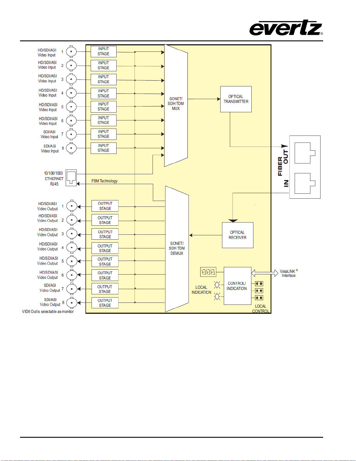
Figure 1-1: 7707VB-8-HS-OC192 Block Diagram ................................................................................................2
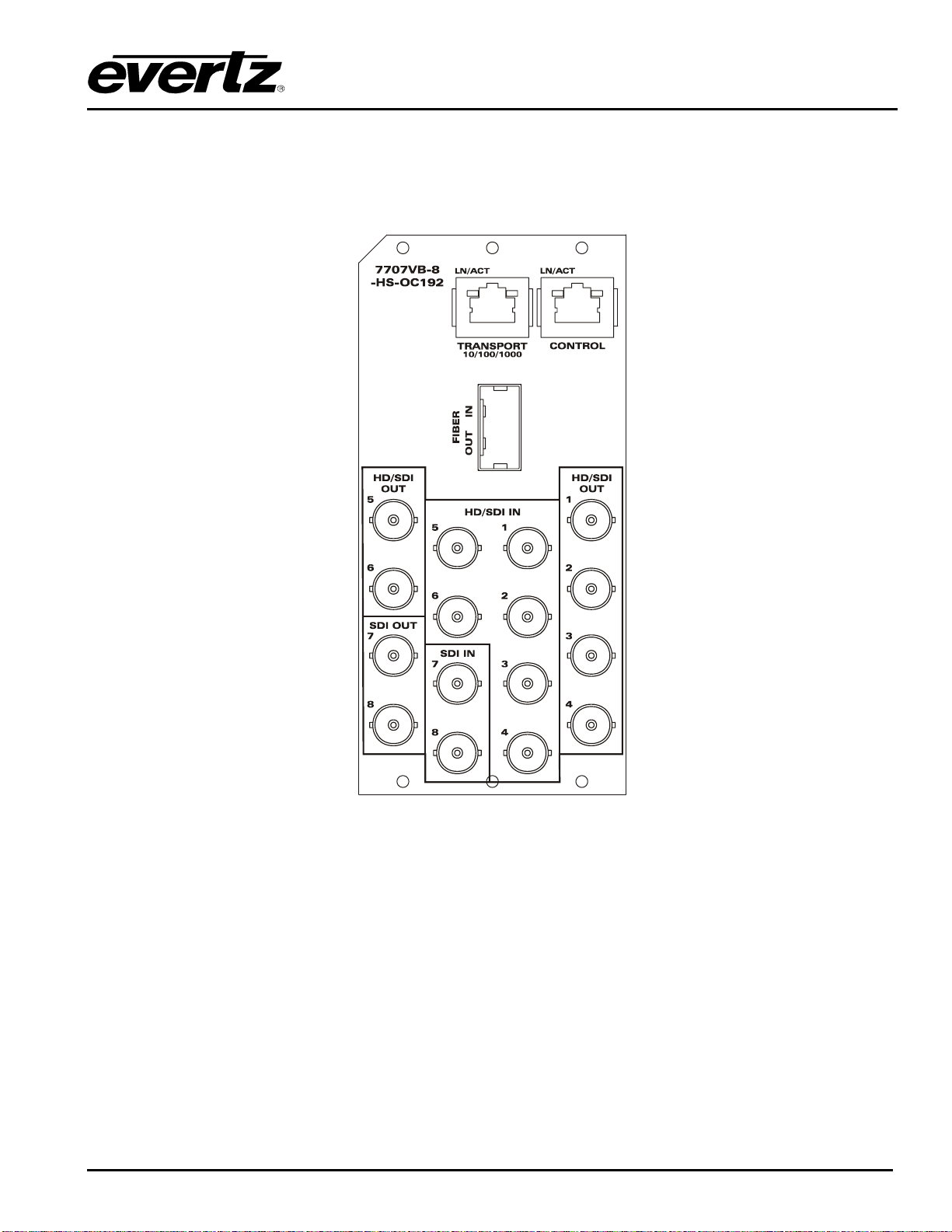
Figure 2-1: 7707VB-8-HS-OC192 Rear Panel......................................................................................................3
Figure 2-2: Reproduction of Laser Certification and Identification Label..............................................................4
Figure 4-1: Location of Status Indicators, Jumpers and Controls.........................................................................8
Figure 4-2: Card Edge Menu Structure (Status Section)....................................................................................11
Figure 4-3: Card Edge Menu Structure (Control Section)...................................................................................19
Tables
Table 4-1: Top Level STATUS Menu..................................................................................................................10
Table 4-2: Top Level CONTROL Menu...............................................................................................................18
Table 6-1: VistaLINK®Monitored Parameters.....................................................................................................27
Table 6-2: VistaLINK®Controlled Parameters....................................................................................................27
Table 6-3: VistaLINK®Traps...............................................................................................................................28