Shuttle Spacewalker HOT-687 User manual

HOT-687
PPGACeleronprocessor
Based AGPMAINBOARD
User's Manual

Shuttle®SpacewalkerTM HOT-687
PPGA Celeron processor based AGPset Mainboard
Manual Version 1.0
Copyright
Copyright©1999 by Shuttle®Inc. All Rights Reserved.
No part of this publication may be reproduced, transcribed, stored in a retrieval system,
translated into any language, or transmitted in any form or by any means, electronic, me-
chanical, magnetic, optical, chemical, photocopying, manual, or otherwise, without prior
written permission from Shuttle®Inc.
Disclaimer
Shuttle®Inc. shall not be liable for any incidental or consequential damages resulting from
the performance or use of this product.
This company makes no representations or warranties regarding the contents of this
manual. Information in this manual has been carefully checked for reliability; however, no
guarantee is given as to the correctness of the contents. In the interest of continued product
improvement, this company reserves the right to revise the manual or include changes in the
specifications of the product described within it at any time without notice and without obliga-
tion to notify any persion of such revision or changes. The information contained in this
manual is provided for general use by the customers.
Trademarks
Spacewalker is a registerred trademark of Shuttle Inc.
Intel, Pentium is a registered trademarks of Intel Corporation.
PC/ATX is a registered trademark of International Business Machines (IBM) Corporation.
PS/2 is a registered trademark of IBM Corporation.
AWARD is a registered trademark of Award Software Inc.
Microsoft and Windows are registered trademarks of Microsoft Corporation.
General Notice: Other brand and product names used herein are for identification purposes
only and may be trademarks of their respective owners.

- 2 -
Federal Communicationsr Commission (FCC)
Compliance Notice
This equipment has been tested and found to comply with the limits for a Class B digital
device, pursuant to Part 15 of FCC Rules. These limits are designed to provide reasonable
protection against harmful interference in a residential installation.
This equipment generates, uses and can radiate radio frequency energy. If not installed and
used properly, in strict accordance with the manufacturer's instructions, may cause harmful
interference to radio communications. However, there is no guarantee that interference will
not occur in a particular installation. If this equipment does cause interference to radio or
television reception, which can be determined by turning the equipment off and on, the user
is encouraged to try to correct the interference by one or more of the following measures :
Reorient or relocate the receiving antenna.
Increase the separation between the equipment and receiver.
Connect the equipment into an outlet on a circuit different from that to which the receiver is
connected.
Consult the dealer or an experienced radio/television technician for help and for additional
suggestions.
The user may find the following booklet prepared by the Federal Communications Commis-
sion helpful "How to Identify and Resolve Radio-TV Interference Problems." This booklet is
available from the U.S. Government Printing Office. Washington, DC 20402, Stock 004-000-
00345-4
CE Notice
This device complies with the requirements oof the EEC directive 89/336/EEC with regard to
EMC (Electromagnetic Compatibility). Following standards are applied to this product, in
order to achieve compliance with the EMC:
Immunity is in accordance with EN 50082-1 (1992).
Emissions are in accordance with EN 55022 (1987) Class B.

- 3 -
TABLE OFCONTENTS
T
T
CHAPTER 1 INTRODUCTION ....................................................................................... 4
CHAPTER 2 FEATURES ............................................................................................ 5
Specification.......................................................................................................................... 5
Accessories of HOT-687 ....................................................................................................... 7
CHAPTER 3 HARDWARE INSTALLATION ....................................................................... 8
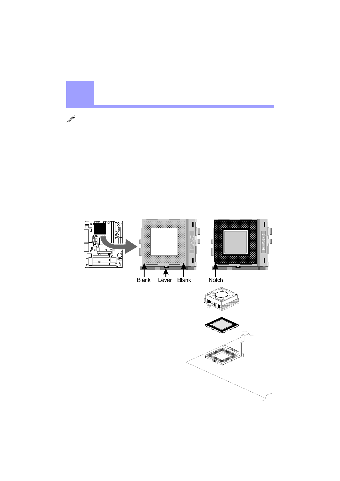
Install The CPU .................................................................................................................... 8
The PPGA Celeron Processor ............................................................................................ 8
Jumpers................................................................................................................................. 9
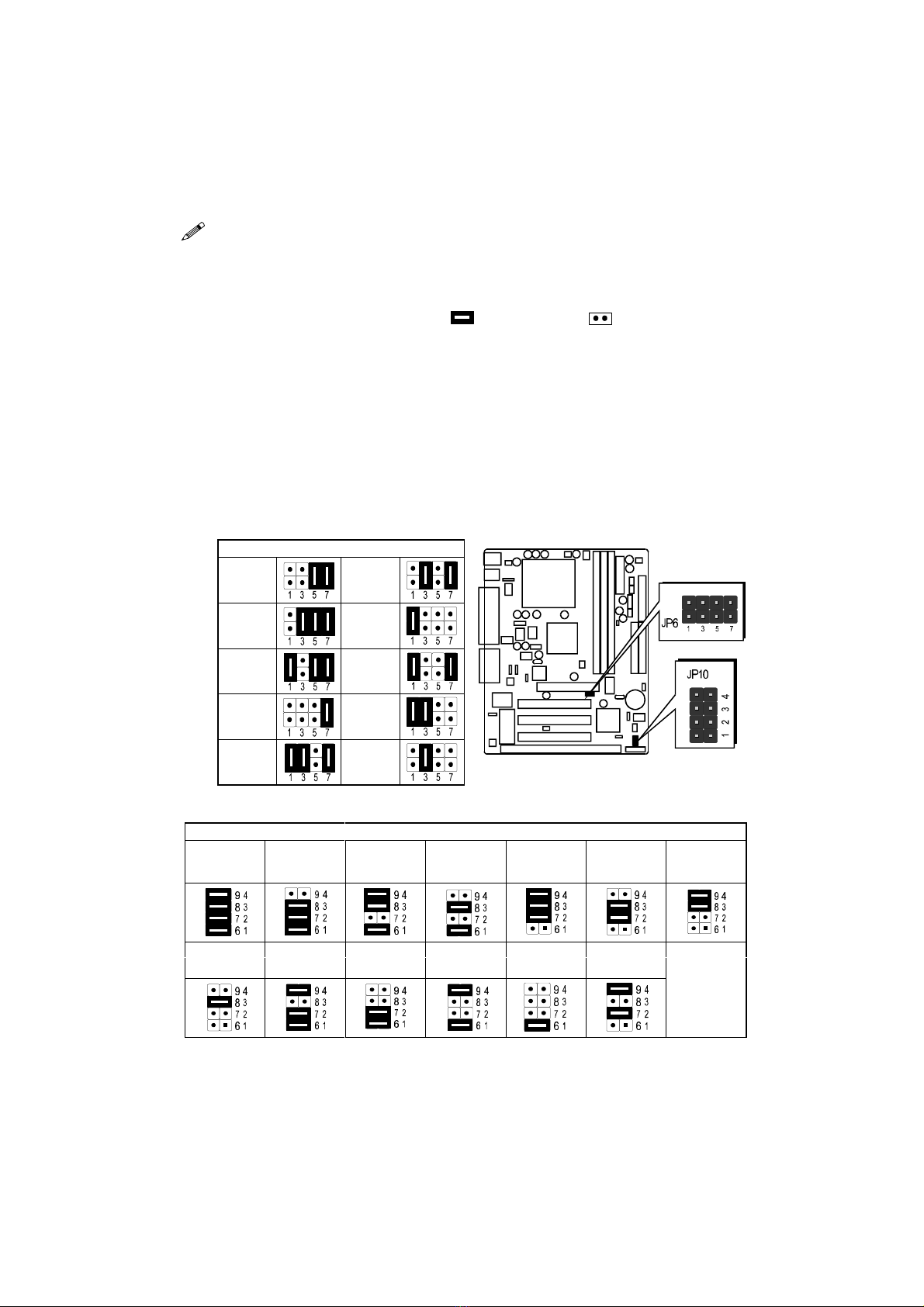
CPU Clock Speed Selection - JP6 and JP10 ...................................................................... 9
On Board Audio Controller Setting - SJP1 ...................................................................... 10
Special Tip for User's Reference Only - JP5.................................................................... 11
Clear CMOS - JP9 ........................................................................................................... 11
Keyboard & PS/2 Mouse Power-on Setting - JP3 ............................................................ 11
Connectors .......................................................................................................................... 12
Front Panel Connectors (JP11) ........................................................................................ 12
(SPEAKER / IDE LED / PW ON / RST / PW LED / EPMI / GREEN LED)
Back Panel Connectors .................................................................................................... 13
(COM1 / COM2 / PS/2 Keyboard & PS/2 Mouse / Parallel Port / USB1 / USB2 /
Line-Out / Line-In / Mic/In / GAME/MIDI)
Other Connectors............................................................................................................. 14
(ATX Power Supply / IR / Audio /FAN / Wake-On-LAN / IDE & Floppy /
SB-LINK)
CHAPTER 4 MEMORY CONFIGURATION ..................................................................... 17
CHAPTER 5 FLASH UTILITY .................................................................................... 18
CHAPTER 6 BIOS SETUP ..................................................................................... 20
The Main Menu .................................................................................................................. 21
Standard CMOS Setup....................................................................................................... 23
BIOS Features Setup .......................................................................................................... 25
Chipset Features Setup....................................................................................................... 28
Power Management Setup ................................................................................................. 31
PCI Configuration Setup.................................................................................................... 34
IntegratedPeripherals ....................................................................................................... 36
Password Setting................................................................................................................. 39

- 4 -
1
1INTRODUCTION
Congratulations on your purchase of the Shuttle® SpacewalkerTM HOT-687 computer mainboard.
HOT-687 is a highly integrated IBM PC/ATX compatible system board designed to meet the industry's
most demanding desktop applications.
Based on the Intel 82440BX AGPset chipset which support up to 500MHz PPGA Celeron processor
with MMX technology.
HOT-687 is equipped with an Accelerated Graphics Port (A.G.P.), a high-performance interconnect
for graphic-intensive application, such as 3D applications. The A.G.P. is independent of the PCI bus
and is designed to exclusively use with graphical-display devices. The HOT-687 supports 3.3 V
A.G.P. devices with data transfer rates up to 133 MHz, allowing data throughput of 500 MB/sec.
The Intel's 82440BX AGPset chipset provides an integrated Bus Mastering IDE controller with two
high performance IDE interfaces which allows up to four IDE devices connection and up to 33 MB/
sec of data transfer rates.
Onboard FM801 is an advanced PCI audio controller, it is compatible with Microsoft Windows,
DirectX and Adlib Music Synthesizer, Sound Blaster Pro and supports thousands of DOS games.
The on-board I/O controller provides standard PC I/O functions:
floppy drive interface, two FIFO serial ports, an IrDA device port and a SPP/EPP/ECP capable
parallel port.
HOT-687 is built with three PCI local bus slots providing a high bandwidth data path for data-
movement intensive functions such as graphics, and with one ISA slot.
HOT-687 provides the foundation for cost effective, high performance and highly expandable plat-
forms, which delivers the latest in the Intel PPGA Celeron processor and new advanced chipset
technology.

- 5 -
2
2FEATURES
The HOT-687 Mainboard is carefully designed for the demanding PC user who wants high
performance and many intelligent features in a compact package:
Intel Chipset:
Features Intel's 440BX AGPset with I/O subsystems.
CPUSupport:
Intel PPGA Celeron processor 300~500 MHz.
VersatileMemory Supports:
Supports three banks of normal or PC/100 SDRAM maximum memory size up to 768MB.
Configurable support for ECC (Error Checking and Correcting)
PCIandISA ExpansionSlots:
Provides three 32-bit PCI slots, one 16-bit ISA slot and one AGP slot.
AGP(Accelerated GraphicsPort):
AGP Specification 1.0
HOT-687 main board equipped with an AGP slot for an AGP VGA card that supports
133MHz 2X mode for texture mapping z-buffering and alpha blending. AGP allows 3D
applications to run faster and smoothly.
Onboard I/O:
One Floppy port;
One PS/2 mouse and PS/2 Keyboard port connector
Two high-speed UART compatible serial ports
Serial Port 2 can also be directed from COM2 to the Infrared Module for wireless connec-
tions. One parallel port with ECP and EPP capabilities.
OnboardAudio Controller:
Proprietary logic for Real DOS games support
Hardware Synthesizer for AdLib and General MIDI compatibility
Optional QSound HSP dynamic 3-D positional audio suport
S/PDIF digital output port
Built-in SRC (sampling rate converter)
Specification

- 6 -
OnboardPCI BusMasterIDE Controller:
Two Ultra DMA/33 Bus Master IDE Ports supports four IDE devices up to 33 MB/sec IDE
transfers and supports Enhanced PIO Modes 3 and 4 and Bus Master IDE DMA Mode 2
devices.
Onboard20-pinATX PowerSupply:
ATX power supply unit can connect to the 20-pin ATX power connector onboard, supporting
Suspend and soft-on/off by dual-function power button.
System BIOS:
Provides licensed Award V4.51PG BIOS on Flash EEPROM.
Supports Green PC, DMI and Bundled with NCR SCSI BIOS.
ACPI:
Support ACPI (Advanced Configuration and Power Interface) function. ACPI provide
more Energy Saving Features for the future operating system supporting OS Direct Power
Management (OSPM) functionality.
Board Size:
ATX form factor 244mm x 190mm.
Advanced Features:
Low EMI -- Spread Spectrum built in - ±0.5% or ±0.3% modulation and automatic clock
shut-off of unused PCI/SDRAMS slots to reduce the EMI.
Dual Function Power Button -- The system can be one of two states, one is Suspend mode
and the other is the Soft-off mode. Pushing the power button for less than 4 seconds will
place the system into Suspend mode. When push the power button for more than 4 seconds,
the system enters the Soft-off mode.
Wake-On-LAN -- The system will power-on automatically by activating of LAN.
(This function support Intel LAN card only).
Modem Ring Power-on -- The system will power-on automatically by activating of modem
ring.
PS/2 Keyboard & Mouse Power-on -- The system will power-on automatically by stroke
keyboard or double click PS/2 mouse.
Optional Features:
Voltages Monitoring -- System voltages levels are monitored to ensure stable current to
main board components.
System voltages include VCORE and VTT for CPU, and +5V, +12V, -5V, -12V for system.
FAN Status Monitoring -- To prevent CPU overheat, CPU fans is monitored for RPM and
failure. (CPU Cooling FAN with RPM sensor is required)

- 7 -
Accessories of HOT-687

- 8 -
Figure 2-2
3
3HARDWARE INSTALLATION
Then you should have a CPU fan that
will cover the face of the CPU. Apply
thermal jelly to the CPU metallic top and
then install the fan onto the CPU. (Figure
2-2 )
Install The CPU
The Installation PPGA Celeron Processor
HOT-687 mainboard provides a 370-pin ZIF Socket370 for Intel PPGA Celeron CPU. The
CPU that came with the mainboard should have a fan attached to it to prevent overheating. If
this is not the case then purchase a fan before you turn on your system.
To install a CPU, first turn off your system and remove its cover. Locate the ZIF Socket370
and open it by first pulling the lever sideways away from the socket then upwards to a 90-
degree right angle. Insert the CPU with the correct orientation as shown.(Figure 2-1) Use
the notched corner of the CPU as your guide. The notched corner should point towards the
end of the lever. Notice that there are two blank area where one hole is missing from that
corner of the square array of pin holes. Because the CPU has a corner pin for two of the four
corner, the CPU will only fit in the one orientationn, hold down on the CPU and close the
socket’s lever.
Figure 2-1

- 9 -
Jumpers
Several hardware settings are made through the use of jumper caps to connect jumper pins
on the main board. The jumper's pin 1 on main board will be on the top or on the left when
holding the main board with the keyboard connector away from yourself.
Jumpers with two pins will be shown as for Close (On) and for Open (Off).
To connect the pins, simply place a plastic jumper cap over the two pins.
CPU Clock Speed and ratio Selection - JP6 and JP10
HOT-687 mainboard features a clock generator to provide adjustable system clock fre-
quency. JP6 is a 8-pin jumpers which determine the system clock frequency 66 MHz to 150
MHz. and JP10 is a 8-pin jumper which determine the processor clock ratio from 2X to 8X.
Figure 2-3 shows the position of JP6 and JP10 on the mainboard.
Table 2-1 shows adjustable System clock on jumper JP6.
Table 2-2 shows adjustable CPU Clock Ratios on jumper group JP10.
SystemClock (JP6)
66 MHz112 MHz
75 MHz124 MHz
83 MHz133 MHz
100 MHz140 MHz
103 MHz150 MHz
MultiplierJP10
2X 2.5X3X 3.5X4X 4.5X5X
(300/100) (350/100) (400/100) (300/66)
(450/100) (333/66)
(500/100)
5.5X6X 6.5X7X 7.5X8X
(366/66) (400/66) (433/66) (466/66) (500/66)
Table 2-2
Figure 2-3
Table 2-1
Note: Present PPGA Celeron CPU Clock ratio is fixed and unable to adjust, for those
processors, JP10 is not functional.

- 10 -
ProcessorSystemClock JP6MultiplierJP10
300 MHz
(66MHz x 4.5)
333 MHz
(66MHz x 5)
366 MHz
(66MHz x 5.5)
400 MHz
(66MHz x 6)
433 MHz
(66MHz x 6.5)
466 MHz
(66MHz x 7)
500 MHz
(66MHz x 7.5)
CPU Host Clock and Clock Ratios Configuration Table (Table 2-3) shows the PPGA Celeron
processor 300 MHz ~ 500 MHz quick setting on the mainboard.
On-board Audio Controller Enabled
On-board Audio Controller Disabled
HOT-687 mainboard provides on-board QSound HSP dynamic 3-D positional audio control-
ler chip. Jumper SJP1 is used to enabled or disabled it.
On Board Audio Controller Setting - SJP1
Table 2-3

- 11 -
Special Tip for User's Reference Only
Table 2-4
K/B&PS/2Mouse Power-OnJP3
Keyboard&
PS/2Mouse
Power-On
Disabled
Keyboard&
PS/2Mouse
Power-On
Enabled
PS/2Mouse
Power-On
Enabled
HOT-687 mainboard provides an optional power-on function by stroke any key (or hot-
key) on keyboard or double click on PS/2 mouse.
Note: Power-on by serial mouse is not supported
JP3 is the jumper used to set the functions of keyboard & PS/2 mouse power-on Enabled
or Disabled.
When you enabled K/B & PS/2 Mouse Power-ON function, you also have to set the
proper item on POWER ON function category of Integrated Peripherals of BIOS
setup.
HOT-687 mainboard supports jumper
JP9 for discharging mainboard's CMOS
memory.
This jumper can clear the CMOS data
stored in the Giga I/O chip. To clear the
CMOS data please follow listed steps:
1) Turn off the PC,
2) Remove mini jumper from JP9 pin 1-2,
3) Insert mini jumper to JP9 pin 2-3 for a
brief while,
4) Remove mini jumper from JP9 in 2-3,
5) Reinsert mini jumper to JP9 pin 1-2,
6) Turn on the PC.
HOT-687 mainboard provides a special Jumper JP5 to overspeed your 66 MHz based Intel
PPGA Celeron processor to 100 MHz when jumper group JP10 set to MANUAL.
Normally, CPU Host Clock 100 ~ 133 MHz are not available for 66 MHz based processor no
matter Soft-Configure or Hard-Configure.
But, when pull out mini jumper from JP5
(let it open), the user can Hard-Configure
your 66 MHz based processor to 100
MHz based. For example, overspeed
your 333 MHz (66 MHz x 5) PPGA
Celeron to 400 MHz (100 x 4) or more.
Clear CMOS - JP9
Keyboard & PS/2 Mouse Power-On Setting - JP3 Figure 2-4

- 12 -
Front Panel Connectors (JP11)
Speaker Connector - SPEAKER
PC speaker connector may attach a 4-pin PC speaker cable from the case to this connector.
HDD LED Connector - IDE LED
Attach a 2-pin IDE drive LED cable to this connector. The LED lights when an IDE device is
active.
ATX Power On/Off Switch Connector - PW ON
Attach a 2-pin momentary type switch to this connector for turning on or off your ATX power
supply.
Hardware Reset Connector - RST
Attach 2-pin hardware reset switch to it. Closing the reset switch restarts the system.
PW-LED Connector - PW LED
Power LED connector is a 3-pin connector for attached to the case's Power LED.
EPMI Connector - EPMI
Hardware System Management Interface connector may attach a 2-pin momentary switch to
it. When push it will force system get into power saving mode, and the system will resume
when switch is pushed again.
GLED Connector - GREEN LED
Attach a 2-pin Green LED cable to it. The Green LED lights when the system get intopower
saving mode.
Connectors
Figure 2-5

- 13 -
Back Panel Connectors
COM1/COM2Connectors
This mainboard can accommodate up to two serial devices on COM1 and COM2.
Attach each serial device cable to the DB9 serial port COM1/COM2 at the back panel of
your computer.
PS/2 Keyboard & PS/2 Mouse Connector
Two 6-pin female PS/2 keyboard & Mouse connectors are located at the rear panel of
the main board. Depending on the computer housing you use (desktop or minitower),
the PS/2 Mouse connector is situated at the top of the PS/2 Keyboard connectoor when
the mainboard is laid into a desktop, as opposed to a mini-tower where the PS/2 Mouse
connector is located at the right of the PS/2 Keyboard's. Plug the PS/2 keyboard and
mouse jacks into their corresponding connectors.
Parallel Port Connector
One DB25 female parallel connector is located at the rear panel of the mainboard. Plug
the connection cable from your parallel device (printer, scanner, etc.) into this connector.
USB1/USB2PortConnectors
Two female connectors USB1/USB2 share the same USB (Universal Serial Bus) bracket
at the rear panel of your mainboard. Plug each USB device jack into an available USB1/
USB2 connector.
Line-Out
Line-Out is a stereo output through which the combined signal of all internal and
external audio sources on the board is output. It can be connected to 1/8-inch TRS stereo
headphones or to amplified speakers.
Line-In
Line-In is a stereo line-level input that accepts a 1/8-inch TRS stereo plug. It can be used
as a source for digital sound recording, a source to be mixed with the output, or both.
Figure 2-6

- 14 -
Mic-In
MIC-IN is a 1/8-inch jack that provides a mono input. It can use a dynamic mono or stereo
microphone with a resistance of not more than 600 ohms.
GAME/MIDI
The GAME/MIDI port is a 15-pin female connector. This port can be connected to any IBM
PC compatible game with a 15-pin D-sub connector.
MIDIInstrumentConnection
You need a MIDI adapter to connect a MIDI instrument to the sound card. The MIDI adapter
can be connected to the Joystick/MIDE port. You will also need MIDI sequencing software to
run MIDI instruments with your computer.
Figure 2-7
Figure 2-8
Figure 2-9
OtherConnectors
ATX Power Supply Connector - J4
It is a 20-pin male header connector is connected to the ATX
power supply. The plug of the power supply will only insert
in one orientation because of the different hole shade and
size. Find the proper orientation and push down firmly
making sure that the pins are aligned.
IR Connector - J3
If you have an Infrared device, this mainboard can implement
IR (Infrared) transfer and meet both ASKIR and HPSIR speci-
fications. To enable the IR transfer function, follow these steps:
Step 1. Attach the 5-pin infrared device cable to J3
connector. (Refer to the above diagram for IR pin
assignment.)
Step 2. Configure the Infrared transfer mode in the
UR2 Mode field of Integrated Peripherals menu
in BIOS Setup. This mainboard supports IrDA
1.0, ASKIR, MIR 0.57M and MIR 1.15M trans
fer modes. FIR is not currently supported.

- 15 -
AudioConnectorsSJ1/SJ2
MODEM/TAD IN/OUT
Port SJ1 can be used to connect a modem audio line to HOT-687. You would use this connec-
tor when using telephone answering machine software for input and output.
TAD
SJ1:
1=PHONE
2=Ground
3=Ground
4=MONO
CD AUDIO INPUT
Port SJ2 is used to attach a CD-ROM audio connector.
CD_IN
SJ2:
1=Left Channel
2=Ground
3=Ground
4=Right Channel
CPU, Chassis & AGP cooling Fan connectors - FAN1, FAN2, FAN3
The main board provides three onboard 12V cooling
fan power connectors. Depending on the fan maker,
the wiring and plug may be different. The red wire should be connected to +12V and black
wire should be connected to ground (GND).
Figure 2-10

- 16 -
Wake-On-LAN Connector - J11
Attach a 3-pin connector from the LAN card which supports the Wake-On-LAN (WOL)
function. This function lets users wake up the connected system
through the LAN card.
Enhanced IDE and Floppy connectors
The mainboard features two 40-pin dual-channel IDE device connectors (IDE1/IDE2)
providing support for up to four IDE devices, such as CD-ROM and Hard Disk Drivers
(H.D.D.). This mainboard also includes one 34-pin floppy disk controller (FDC) to accom-
modate the Floppy Disk Drive (F.D.D.).
This mainboard comes with one 40-pin ribbon cable to connect to IDE H.D.D and one 34-pin
ribbon cable for F.D.D.
Ribbon cables are directional, therefore, make sure to always
connect with the red cable-strip on the same side as pin #1 of
the IDE1/IDE2 or FDC connector on the mainboard.
SB-Link connector - JP7
The main board provides a 2x3 pin SB-Link header accepts the Creative CT4600 series PCI
sound cards with PCI solution to connect the legacy Sound Blaster compatible audio to the
PCI bus.
Figure 2-11

- 17 -
MEMORY CONFIGURATION
4
4
The HOT-687 mainboard provides three 168-pin DIMM sockets that make it possible to
install from 8MB up to 768MB of SDRAM. The DIMM socket support 8MB, 16MB,
32MB, 64MB, 128MB and 256MB 3.3V single- or double- side SDRAM DIMM.
The three DIMM sockets are arranged in three banks of one socket each, Each bank pro-
vides a 64/72-bit wide data path.
HOT-687 provides optional data integrity features including EC (Error Checking) or ECC
(Error Checking and Correcting) in the memory array. EC mode provides single and
multiple bit error detection. In ECC mode, during reads from the DRAM, the HOT-687
provides error checking and correction of the data.
To support ECC, you must use true (opposed to phantom parity generated by TTL chips) 72-
bit parity-type DIMM for all modules.
Install Memory
Install memory in any or all of the banks and in any combination, as follows:
DIMM
Socket MemoryModulesMoudule
Quantity
DIMM 18MB,16MB,32MB,64MB,128MB,256MB
168-pin3.3VSDRAMDIMM x1
DIMM 28MB,16MB,32MB,64MB,128MB,256MB
168-pin3.3VSDRAMDIMM x1
DIMM 38MB,16MB,32MB,64MB,128MB,256MB
168-pin3.3VSDRAMDIMM x1
Table 3-1
Upgrade Memory
You can easily upgrade the system memory by inserting additional SDRAM modules in
available DIMM banks. The total system memory is calculated by simply adding up the
memory in all DIMM banks. After upgrade, the new system memory value will automati-
cally be computed and displayed by the BIOS Standard CMOS Setup menu.

- 18 -
5
5FLASH UTILITY
This chapter briefly discusses Award Flash utility in order to guide you through updating
your old BIOS. The file name we use to program here is test.bin, and the file name to save
old BIOS is 687.OLD. Please note that those file names are not absolute. They are only
examples to let you have a more clear understanding of the updating process.
How to Begin
1. Please type “awdflash” and press the ENTER key to begin the updating process.
2. Once you enter, you will see a main menu displaying:
3. Move the cursor to “File Name to Program: “
4. Type the program name “test.bin”, and then press the ENTER key.
5. At the bottom of the menu, you will be requested to answer:
“Do You Want to Save BIOS (Y/N)? “
The following manual is intended to guide you through the process of both “No” and “Yes”
cases respectively.
If “No”
If you do not wish to save the old BIOS:
1. Please type “N”, and then press the ENTER key.
2. Then you will be requested to answer:
“Are You Sure to Program? “
3. Answer “N” if you do not want to program, and then it will exit.

- 19 -
5. Type “Y” to begin programming, and press the ENTER key.
6. When the programming is finished, the showing message will appear:
7. Once you see the showing message “Power Off or Reset System”, please restart your
system.
8. When you power on the computer again, you will find your old BIOS has already
been successfully updated.
To view a complete usage of FLASH utility, please type “awdflash /?” and press the EN-
TERkey.
Notes About Award Flash Utility
Please note that Award Flash Utility cannot run under EMM386 or QEMM. Thus, when
executing the command “awdflash”, an error message will appear:
“Error Message: Fail — Due to EMM386 or QEMM !”
If “Yes”
To save the old BIOS:
1. Please respond “Y”, and then press the ENTER key.
2. Move the cursor to “File Name to Save: “
3. Type file name “TEST.BIN”, and then press the ENTER key. (Your old BIOS will be
saved in the file name you create. In this case, the old BIOS is saved in the file
name,687.OLD).
4. Then you will be requested to answer:
“Are You Sure to Program (Y/N)? “
Table of contents
Other Shuttle Motherboard manuals

Shuttle
Shuttle Spacewalker AK11 User manual

Shuttle
Shuttle FB61 User manual

Shuttle
Shuttle HOT-555 User manual

Shuttle
Shuttle HOT-565 User manual

Shuttle
Shuttle AK32A User manual

Shuttle
Shuttle HOT-637 User manual

Shuttle
Shuttle FN85 User manual

Shuttle
Shuttle HOT-617 User manual

Shuttle
Shuttle AT30 User manual

Shuttle
Shuttle AB60P User manual

Shuttle
Shuttle AB60/R User manual

Shuttle
Shuttle FX83 User manual

Shuttle
Shuttle FB52 User manual

Shuttle
Shuttle FN41V3 User manual

Shuttle
Shuttle FX43G User manual

Shuttle
Shuttle FB77 User manual

Shuttle
Shuttle Spacewalker MV18 User manual

Shuttle
Shuttle Spacewalker AB40 User manual

Shuttle
Shuttle Spacewalker FE22 User manual

Shuttle
Shuttle Spacewalker AK31 User manual