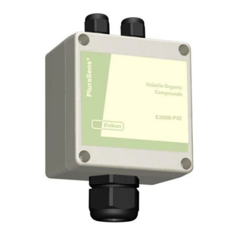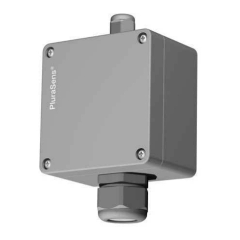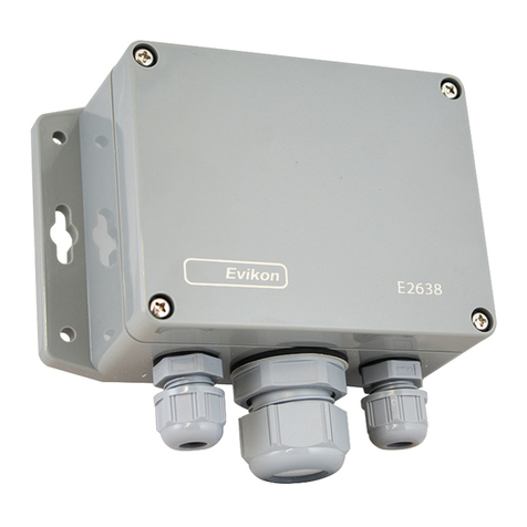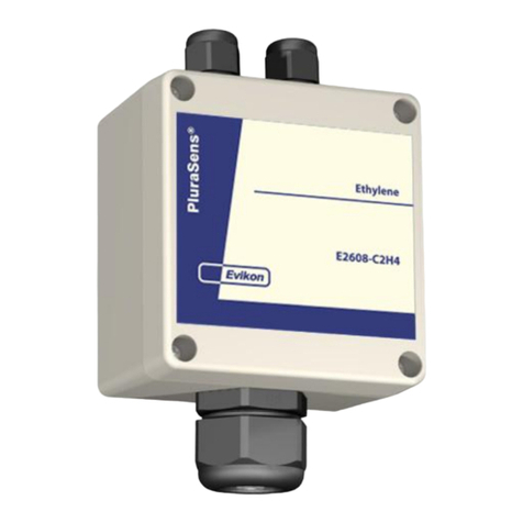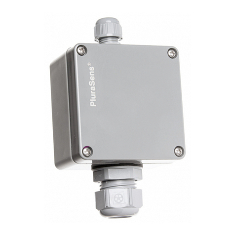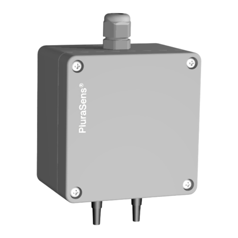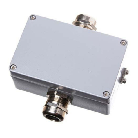
Carbon dioxide transmitter E2618-CO2 is a member of new PluraSens® family of
multifunctional measurement instruments. Applications include HVAC and air
quality control in public, office and industrial buildings, greenhouses, underground
parkings, and other confined spaces, where potentially toxic concentration of
carbon dioxide can accumulate.
The instrument utilises digital fully calibrated and temperature compensated optical
(NDIR technology) gas sensor with excellent repeatability, stability and long
lifetime. The transmitteris supplied either in duct-mount or wall-mount version. The
wall mount version of the transmitter is available with remote probe. The remote
probe is connected to the main unit with shielded cable. The connection cable
length options are 2.5 m or 5 m.
Two freely configurable 4-20 mA or 0-10 V analog outputs can be used to connect
the transmitter to secondary instruments. RS485 interface with industry-standard
Modbus RTU protocol allows direct Fieldbusnetworking of the transmitter.
Safety requirements
Always adhere to the safety provisions applicable in the country of use.
Do not perform any maintenance operation with the power on. Do not let water or
foreign objects inside the device.
Operating conditions
The device should be used in explosion-safe (non ATEX -rated) indoor areas,
without aggressive gases in the atmosphere. Avoid electrostatic charging of the
transmitter. See Specifications table for moreinformation.
Installation and connection
1. Duct mount version: Connect the sensor probe to the device main unit. Make
sure that the connections are tightened properly.
Cut a 30 mm diameter hole in the air duct at the chosen mounting place. Place the
rubber flange in the hole and fix it with three self-tapping screws. Pass the sensor
probe through the flange and adjust it to the appropriate depth. Unscrew four lid
screws and detach the lid from the instrument.
Wall mount version: Unscrew four lid screws and detach the lid from the
instrument. Fix the transmitter through mounting holes by screws.
The transmitter should be located 60...80 cm from the floor to control leakages or
in the breathing zone (1,2...1.5 m from the floor) for air quality control. Locate your
device away from ventilation holes or dead-air spaces such as corners. The
recommended orientation of sensor probe is vertical with the sensor tip pointing
downwards. Coverage area for each transmitter is 500...1000 m2(12...18 m
radius).
2. Plug the power cable and connectthe analog outputs and/or digital interface
terminals to the relevant devices according to the connection diagram.
Make certain that the cable gland is properly tightened to ensure the conformity to
IP65 protection class.
The screwless quick connect spring terminals on the E2618 series devices are
suitable for a wide range of wires with cross-section 0,2...1,5 mm2. The
recommended wire stripping length is 8...9 mm. Push the spring loaded terminal
lever, insert the wireend into terminal hole and releasethe lever.
Use twisted pair cable, e.g. LiYY TP 2×2×0,5 mm2or CAT 5, to connect the device
to RS485 network. Use one pair for A and B wires and the second pair for common
0 V and power +U wires. to connect the transmitter to Fieldbus network. Respect
polarity. Overall length of all connections via RS485 interface should not exceed
1200 m.
Place the lid back and tighten itwith the four screws.
Note Avoid exposing the sensor to any mechanical stress during installation or
operation sinse this may damage the device and lead to relevant measurement
errors.
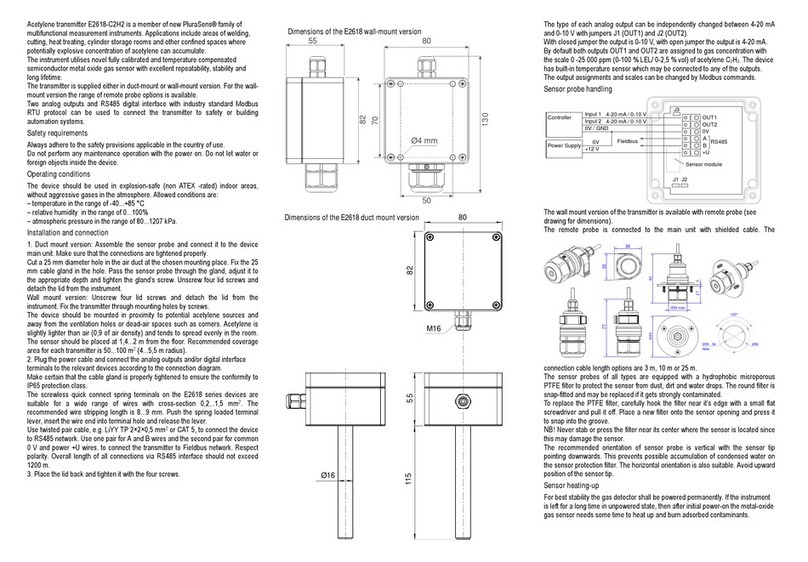
The type of each analog output can be independently changed between 4-20 mA
and 0-10 V with jumpers J1 (OUT1) and J2 (OUT2).
With closed jumper the output is 0-10V, with open jumper the output is 4-20 mA.
By default both outputs OUT1 and OUT2 are assigned to gas concentration. The
device has built-in temperature sensor wich may be connected to any of the
outputs.
The output assignments and scales can bechanged by Modbus commands.
Emergency mode
The current outputs ofthe transmitter may be programmed via Modbus commands
to signal if the connection with the sensor is lost. The signal maybe set to 3,8 mA
or 21,5 mA. See the table of Modbus registers for more information.
Return to default settings
To reset the device’s Slave ID, baudrate andsbit number to factory settings,
proceed as follows:
1. De-energize the device
2. Connect the J3 jumper
3. Turn on the device
4. De-energize the device
5. Disconnect the J3 jumper
6. Turn on the device
Calibration
Two optical sensor options are available.
Type A double-beam sensor has a built-in reference sample for autocalibration.
Manual calibration by fresh air should beperformed once in 5 years.
Type B sensor performs autocalibration by settling the minimal CO2concentration
to 400 ppm. To use this type it is required that CO2 level decreases to fresh air
level at least once a week. Transmitters with B-type sensors should not be used in
areas with constantly high CO2 level (greenhouses,hospitals etc).
Delivery set
– Carbon dioxide transmitter E2618-CO2 or E2618-CO2-DM
– Mounting accessories:
4 screws with plastic dowels for wall mount version
rubber flange with 3 self-tapping screws for duct mount version.
fixing clamp for remote probe versions
Warranty
This product is warranted to be free from defects in material and workmanship for a
period of one year from the date of original sale. During this warranty period
Manufacturer will, at its option, either repair or replace product that proves to be
defective. This warranty is void if the product has been operated in conditions
outside ranges specified by Manufacturer or damaged by customer error or
negligence or if there has been an unauthorized modification.
4-20 mA/ 0-10 V
4-20 mA/ 0-10 V
0V / GND
0V
Controller
Power Supply
Input 1
Input 2 OUT1
OUT2
0V
A
BRS485
+U
J1 J2
Fieldbus
Sensor module
+12 V
J3
Dimensions of the E2618-CO2 wall-mount version and the remote probe
Dimensions of the E2618-CO2 duct mount version
Ø28
55
80
152
82
80
Ø28
