EVoCharge 30A EVoReel iEVSE Assembly instructions

EVoReel
INSTALLATION GUIDE
AND USER MANUAL
Electric Vehicle Charging Station
Version 2.4
Model: 30A EVoReel iEVSE
Model Numbers: EV072-110-001A, 002A, 003A, 011A, 012A, 013A
Product Safety Certification: Retractable Reel: ETL and cETL Listed; EVSE: UL and cUL Listed
Description: SAE J1772 AC Level 2, 30A Continuous Rated EVSE with Retractable Reel

©2012-2015 EVoCharge - All Rights Reserved
All information in this document is subject to copyright and other intellectual property rights of EVoCharge. This material may not
be modified, reproduced or copied, in whole or in part, without the prior written permission of EVoCharge. EVoCharge and EVoReel
are trademarks of EVoCharge. All other trademarks contained in this document are the property of their respective owners and
their use herein does not imply sponsorship or endorsement of their products or services. All specifications and descriptions
contained in this document are verified to be accurate at the time of printing. However, to support continuous improvement,
EVoCharge reserves the right to make product modifications at any time without notice. Updated installation guide and users
manual is available at www.evocharge.com
2
IMPORTANT
Read this manual thoroughly and make sure you understand the procedures before you attempt to
install or operate this equipment. The purpose of this manual is to provide you with information
necessary to safely install, operate and maintain this equipment. Keep this manual for future
reference.
It is recommended that all EVoCharge products be installed by a qualified electrician, and
installation must be in accordance with all applicable state, local and national electrical codes and
standards. Failure to observe this precaution could result in death or severe injury.
Warranty: The EVoReel products are covered by a two-year limited warranty. For a detailed
description of this warranty, contact EVoCharge:
Telephone: (800) 930-9450

3
CONTENTS
SAFETY INFORMATION………………………………………………….4-5
IMPORTANT REFERENCE INFORMATION………………….……6
SPECIFICATIONS……………………………………………………….….. 7
FEATURES……………………………………………………………….…….8
INSTALL PLANNING AND SERVICE WIRING…………………… 9
INSTALLATION………………………………………………………..….… 10-23
OPERATION………………………………………..…………………………24-26
SAVE THESE SAFETY INSTRUCTIONS
•The Charging Station must be grounded through a permanent wiring system or an equipment grounding conductor.
•Do not install or use the Charging Station near flammable, explosive, harsh, or combustible materials, chemicals, or vapors.
•Turn off input power at the circuit breaker before installing or cleaning the Charging Station.
•Use the Charging Station only within the specified operating parameters.
•The Charging Station is designed only for vehicles that are compatible with the SAE J1772 AC Level 2 charging standard.
•Do not use the Charging Station if it is defective, appears cracked, frayed, broken or otherwise damaged, or fails to operate.
•Do not attempt to open, disassemble, repair, tamper with, or modify the Charging Station. The Charging Station is not user serviceable.
Contact EVoCharge for any repairs.
•Do not use the Charging Station when either you, the vehicle, or the Charging Station is exposed to severe rain, snow, electrical storm or
other severe weather.
•When transporting the Charging Station, handle with care and do not subject it to strong force, drag or step on the Charging Station.
•Do not touch the Charging Station end terminals with sharp metallic objects.
•Do not forcefully pull the charge cable or damage it with sharp objects.
•Do not insert foreign objects into any part of the Charging Station vehicle connector.
•Using with a worn or damaged AC outlet may cause burns or start a fire.
•If the AC wall plug feels hot while charging, unplug the unit and replace the AC outlet.
•To avoid a risk of fire or electric shock, do not use this device with an extension cord.
•Risk of explosion. This equipment has arcing or sparking parts that should not be exposed to flammable vapors. This equipment should be
located at least 18 inches (460mm) above the floor.
•Risk of electric shock. Do not remove cover or attempt to open the enclosure of the charger unit. No user serviceable parts inside. Refer
servicing to qualified service personnel.
•Unit will attempt to reset in fault conditions.
•This device is intended only for charging vehicles not requiring ventilation during charging.
Warning
4
-Continued on next page-
This document contains important instructions and warnings that must be followed when installing and maintaining the Charging Station

5
•Incorrect installation and testing of the Charging Station could potentially damage either the vehicle’s Battery and/or the Charging Station
itself. Any resulting damage is excluded of the warranty for the Charging Station.
•Do not operate the Charging Station in temperatures outside its operating range of -22F (-30C) to 122F (50C).
•Ensure that the charge cable is positioned so it will not be stepped on, tripped over, or subjected to damage or stress.
•To reduce the risk of electrical shock, connect only to properly grounded outlets.
•If the plug provided does not fit the outlet, do not modify the plug, arrange for a qualified electrician to inspect the outlet.
•This equipment should be installed, adjusted, and serviced by qualified electrical personnel familiar with the construction and operation of
this type of equipment and the hazards involved. Failure to observe this precaution could result in death or severe injury. The user is
responsible for conforming to all local and national electrical codes and standards applicable in the jurisdiction in which this equipment is
installed.
•Confirm with the local electrical requirements for the gauge, temperature rating, and type of wire material used for the overcurrent rating
to support a dedicated circuit of 208/240 VAC 40A upstream of two-pole circuit breaker.
•Do not use this product if the EV Cable is frayed, has damaged insulation, or any other sign of damage.
•Do not use this product if the enclosure or the EV connector is broken, cracked, open, or shows any other indication of damage.
•Lockout all electrical source circuit feeding he charging unit In the open position before beginning wiring or terminations. Failure to follow
the instructions could result in server bodily injury or death.
•This unit is rated for indoor or outdoor installation. If this unit is mounted outdoors, the hardware for connecting the conduits to the unit
must be rated for outdoor installation and be installed properly to maintain the proper NEMA rating on the unit.
•It is important that power wires are routed through an approved conduit or jacket from the circuit panel to the unit.
Caution
SAVE THESE SAFETY INSTRUCTIONS
This document contains important instructions and warnings that must be followed when installing and maintaining the Charging Station
For more information on how to charge your specific vehicle, refer to the owners manual provided with your vehicle.
•All EVoCharge and EVoReel products do not require routine maintenance however, periodic
inspections should be conducted to ensure that all parts remain in good working order and no
damage exists. Do not attempt to open, disassemble, repair, tamper with, or modify any
components of the products –the products are not user serviceable. Contact EVoCharge for any
repairs.
•Periodic cleaning may be required, depending on local conditions. To avoid damaging the finish of
the products, only use an automotive grade soft cleaning cloth and a mild soap and water mixture to
remove accumulation of dirt and dust. Do not use cleaning solvents to clean any of the product
components.
•When moving or lifting the unit, always grasp the mounting bracket of the retractable reel . Never
attempt to lift, move, or carry the unit by any of the electrical cables. Improper handling may cause
damage to the unit.
IMPORTANT REFERENCE INFORMATION
6
SPECIFICATIONS
7
SPECIFICATIONS
Part Numbers
EV072
-110-002A: RFID/Networked iEVSE, 3 ft. Interconnect, 30 ft. Charge Cable
EV072
-110-001A: RFID/Networked iEVSE, 10 ft. Interconnect,
30 ft. Charge Cable
EV072
-110-003A: RFID/Networked iEVSE, 20 ft. Interconnect,
30 ft. Charge Cable
Connector / EVSE Level SAE J1772; AC Level 2
Max Output Rating 30A; 7.2 kW
Input Voltage 208-240VAC, 50/60 Hz
Electrical Circuit / Input
Power Requirements
Circuit Rating Requirement: 40 Amperes; Branch Breaker: 40 Ampere double
pole Circuit Conductors: Line 1, Line 2, Earth Ground
Charge Cable Length 30 ft. (9.14m)
Interconnect Length 3, 10, 20 ft. 3, 10, 20 ft. (0.92, 3.05, 6.10m)
Color Black (Standard); White (Optional)
Installation Ratings Indoor/Outdoor Rated; Reel: NEMA 4 ; EVSE: NEMA 3R
Mounting Designed for Single Stud Wall, Ceiling (Overhead) & Pedestal Installation
Overall Weight &
Dimensions
Weight: 58 lbs. (26.3 kg)
EVoReel: 13.8 x 12.0 x 9.2 inches (35.1 x 30.5 x 23.3 cm)
EVSE: 15.0 x 10.6 x 4.7 inches (38.1 x 26.9 x 12.0 cm)
Operating Temperature EVSE: -30⁰C to 50⁰C (-22⁰F to 122⁰F); EVoReel: -45⁰C to 50⁰C (-49⁰F to 122⁰F)
Charge Status Indicators Power/Ready, Charging, Fault
Cable Management System
EVoReel Retractable Reel
EVSE Type
Intelligent: RFID Access Control
and OCPP-
enabled network capability for payment
and access control. Protocol: OCPP 1.5 thru Ethernet / GPRS
Standards SAE J1772, UL 2594, UL 355
Regulatory Compliance EVSE: UL and cUL Listed; Retractable Reel: ETL and cETL Listed
FEATURES
8
FEATURES
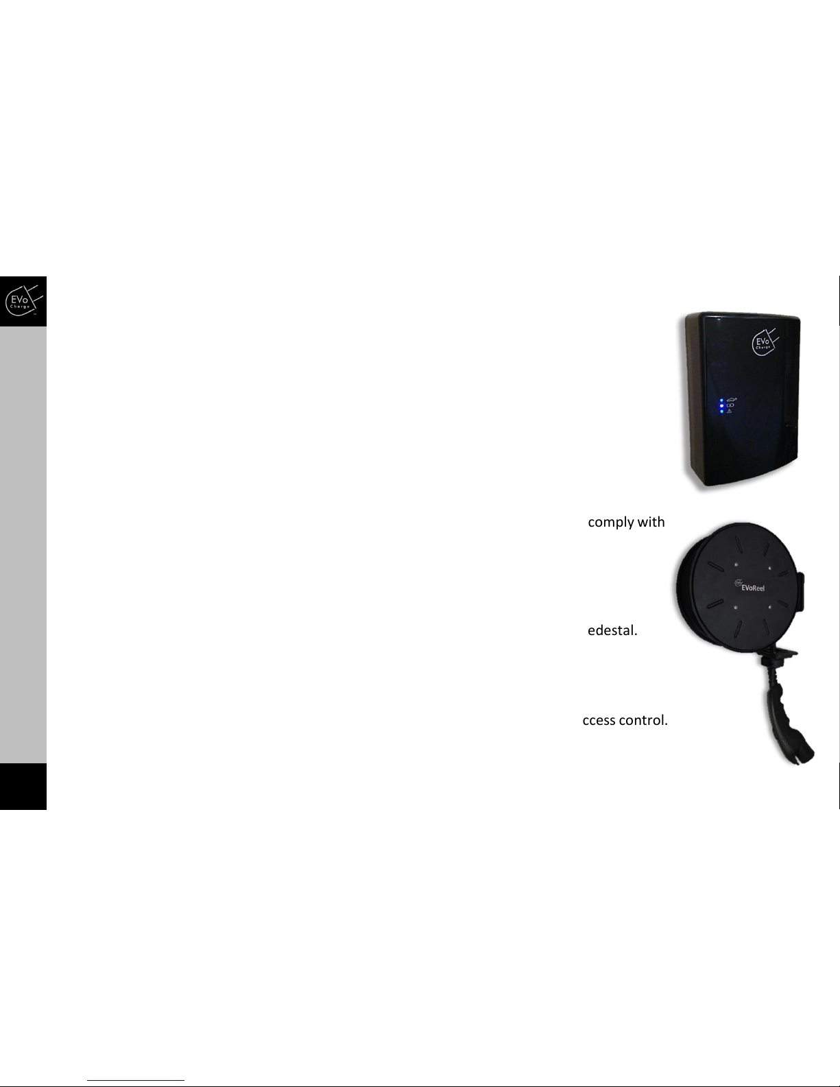
Retractable Reel
All EVoReel Charging Stations provide added convinience to the user by utilizing a retractable
reel for charge cable management. The retractable reel includes a vehicle charge cable up to
30 feet in length.
Indoor/Outdoor Rated Enclosures (NEMA 3R)
The EVoReel Charging Stations are rated for both indoor and outdoor charging and comply with
NEMA 3R standards.
Versatile Mounting
The retractable reel mounting bracket allows for mounting on the wall, ceiling, or pedestal.
Access Control & Payment Capability
RFID Card Access Control and OCPP-enabled network capability for payment and access control.
INSTALL PLANNING / SERVICE WIRING
9
INSTALL PLANNING AND SERVICE WIRING
•Prior to mounting, determine location of an acceptable mounting support. The Wall or Ceiling mount
unit must be anchored into a mounting support such as a 2” x 4” stud or a solid concrete wall, using
mounting hardware that is appropriate for the surface on which you are mounting. DO NOT mount this
unit directly to a stucco/drywall/wall board. If installing on a wood stud use the lag screws provided and
ensure the mounting plate is positioned on the centerline of the stud. If mounting onto a concrete,
block, or brick wall, use an appropriate anchor for the type of wall on which you are installing the unit.
•Prior to mounting, locate an available electrical source that can support the following Input
Requirements for the EVoReel Charging Station:
•Per National Electric Code (NEC) requirements, to support 30A continuous output current, a
DEDICATED CIRCUIT rated for 40A; 208-240 VAC, 60 Hz, must be used. It is recommended to
utilize a 40A upstream circuit breaker, located either in a panel board or load center.
•The Charging Unit has a built in GFCI protection; do not provide any additional GFCI protection
upstream of the charging unit.
•The EVoReel Charging Stations provide the option to connect to either a NEMA 6-50 Receptacle
the units can be hardwired.
•30A EVoReel iEVSE product only: To allow for network connection –install a standard CAT5/6 network
cable to the unit. The CAT5/6 network cable connects to the Ethernet port at the bottom of the EVSE.
Important: The service wiring in this section are specific to North America only.
Warning: Before installing the EVoReel Charging Station, identify the type of utility service connection available onsite.
If you have unsure about the type of connection available at the service panel, contact your utility service provider.
INSTALLATION
10
INSTALLATION
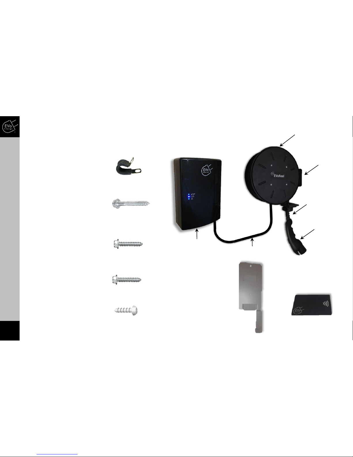
STEP 1 –Verify Received Content
Charging Unit Wall
Mounting Bracket
Quantity: (1)
M3 Torx Screw
Quantity: (1)
(For use to secure Charging Unit
to Wall Mounting Bracket)
1/4” Lag Screws
Quantity: (2)
(For use when mounting
Charging Unit to concrete wall)
3/8” Lag Screws
Quantity: (3)
(For use when mounting reel to
wall/ceiling wooden wall stud)
Interconnect Support Clamp
Quantity (4)
(For use to support Interconnect
cable following installation)
Interconnect
Vehicle
Connector
Charge Cable
Mounting
Bracket
EVSE
Charging Unit
Retractable Reel
#12 Lag Screws
Quantity: (2)
(For use when mounting Charging
Unit to wood wall stud)
RFID Access Cards
Quantity: (4)

INSTALLATION
STEP 2 –Adjust Retractable Reel Roller Guide Arm Position
1
1. Prior to mounting retractable
reel, determine the preferred
position of the roller guide arm.
The roller guide arm can be
adjusted into (12) different
locations based on your
installation method. The roller
guide arm can be adjusted by
removing the 5/16 hex head
screw and lock washer. The guide
position should be selected and
secured prior to making any
electrical connections.
INSTALLATION
11

INSTALLATION
STEP 3 –Install Retractable Reel
Mounting Option “A”
Mounting Option “B”
1. Determine preferred
height and orientation
of retractable reel. It is
recommended to install
retractable reel at the
maximum height based
on interconnect cable
length. The retractable
reel can be mounted
using mounting option
“A” or “B”.
INSTALLATION
12
1
INSTALLATION
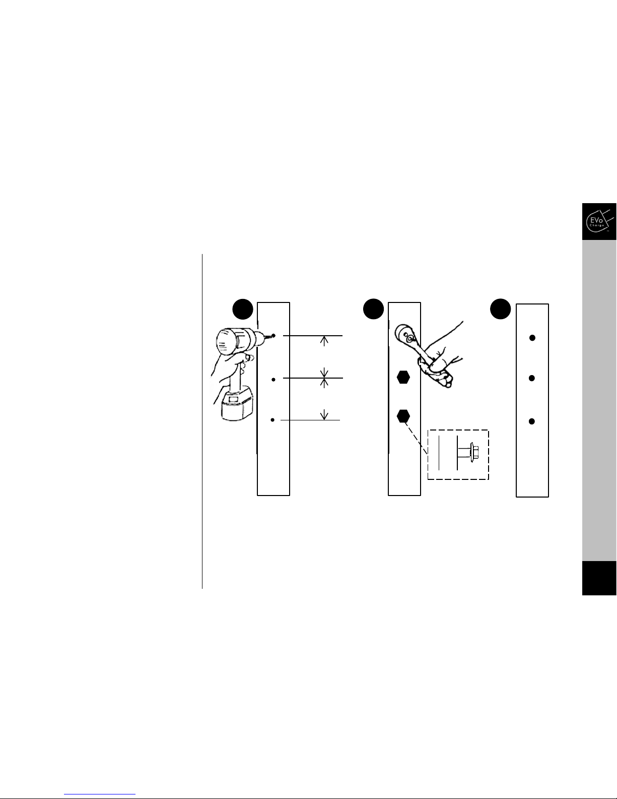
STEP 4 –Install Retractable Reel
Wall Stud
1. Locate a wall stud and use a 1/4”
bit to drill a pilot hole for each
mounting hole. The (3) mounting
holes are positioned 1.625” away
from each other.
2. Prepare mounting hole by
Fastening lag screw into top of
each mounting hole until lag screw
enters partially into wall stud.
3. Remove all lag screws from
mounting holes.
WARNING: All lag screws MUST be used
to install the charging unit to the
vertical wall stud. Each lag screw MUST
be securely fastened to THE CENTER of
the wall studs. Please contact and use
a professional installer if necessary, or
consult a licensed contractor for the
best anchoring options.
1.625”
Wall Stud
2
Wall Stud
1 3
1.625”
Partially Secure
INSTALLATION
13
INSTALLATION
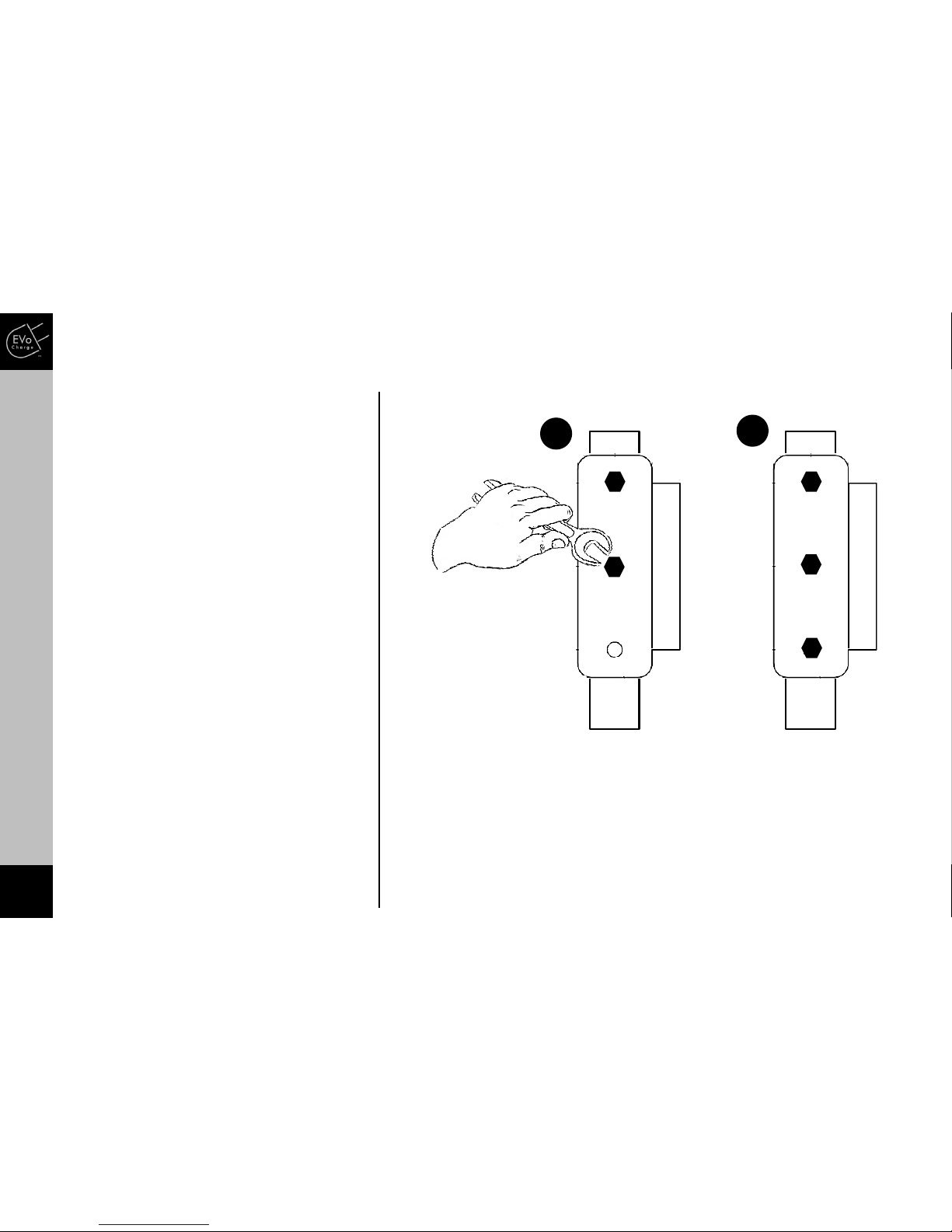
STEP 5 –Install Retractable Reel
1. Place reel mounting bracket over
mounting holes and fasten lag screw.
2. Continue fastening lag screws into
each mounting hole.
WARNING: All lag screws MUST be used to
install the charging unit to the vertical wall
stud. Each lag screw MUST be securely
fastened to THE CENTER of the wall studs.
Please contact and use a professional
installer if necessary, or consult a licensed
contractor for the best anchoring options.
1 2
INSTALLATION
14

INSTALLATION
1. Adjust retractable reel ball stop
position by using a screwdriver to
loosen both fasteners.
2. Adjust the ball stop to a position
that enables a convenient vehicle
connector rest position.
3. Fasten and secure the ball stop to
vehicle charge cable.
2
1 3
INSTALLATION
15
STEP 6 –Adjust Vehicle Connector Position

INSTALLATION
1. Depending on the cable stop
placement from installation step
6, the retraction rate of the reel
may need adjustment. This can
be accomplished by manually
adjusting the number of charge
cable wraps around the reel. Add
additional charge cable wraps to
the reel to increase the retraction
rate. Remove charge cable wraps
from the reel to reduce the
retraction rate.
STEP 7 –Adjust Reel Retraction Rate (if required)
1
INSTALLATION
16
INSTALLATION
17
INSTALLATION
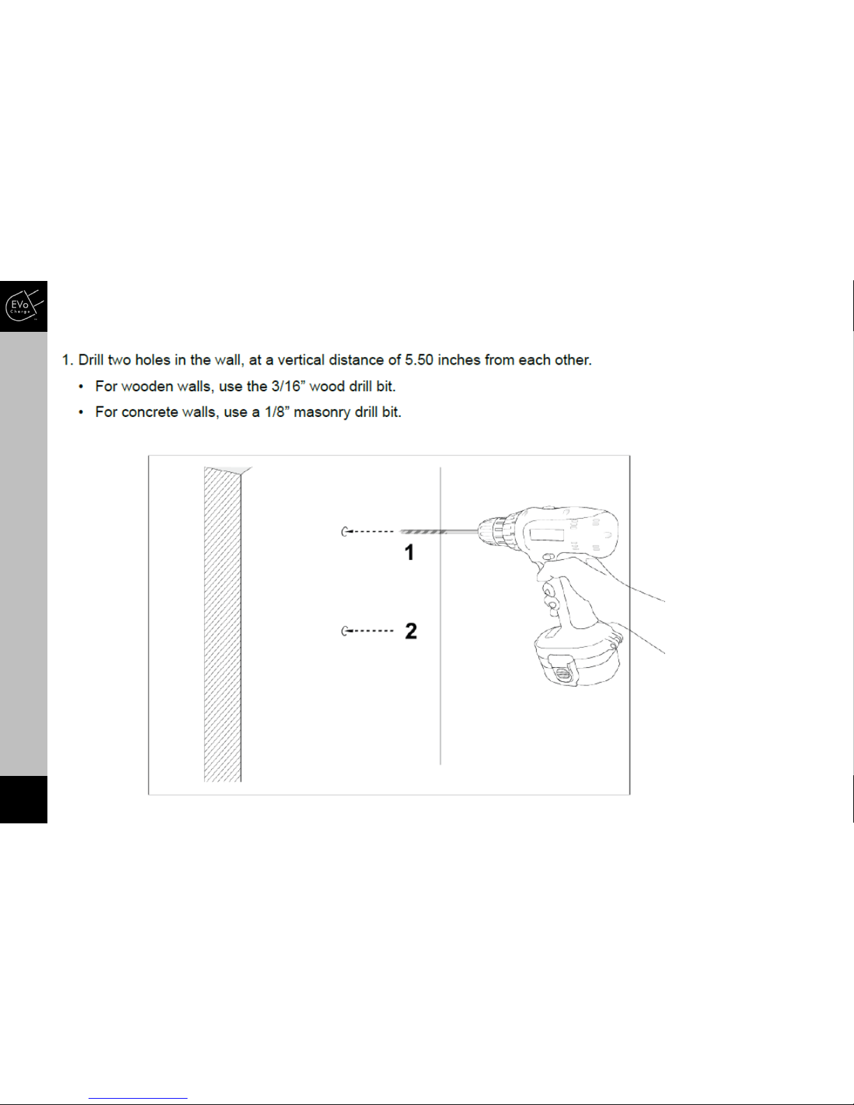
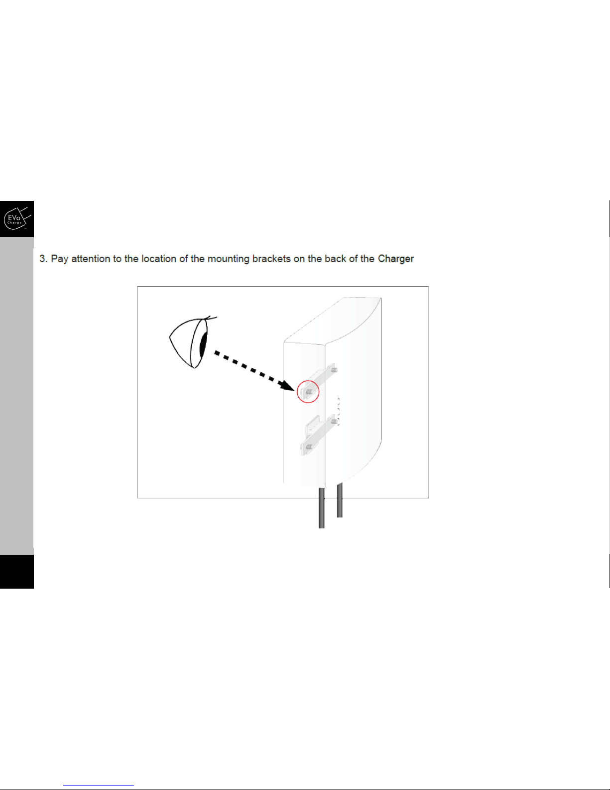
STEP 8 –Mounting the Charging Unit

18
INSTALLATION
STEP 8 –Mounting the Charging Unit
INSTALLATION
19
INSTALLATION
STEP 8 –Mounting the Charging Unit

20
INSTALLATION
STEP 8 –Mounting the Charging Unit
Table of contents
Other EVoCharge Automobile Accessories manuals


