Evolution PURE MINERALS LS70 User manual

Installation and Operation Manual for
PURE MINERALS™ LOW SALT OXIDISER & SANITISER
LS70
This equipment must be installed and serviced by a qualied technician. Improper installation can create electrical
hazards which could result in property damage, serious injury or death. Improper installation will void the warranty.
This manual contains important information about the installation, operation and safe use of this product. Once
the product has been installed this manual must be given to the owner/operator of this equipment.

TABLE OF CONTENTS
1.0 FOREWORD . . . . . . . . . . . . . . . . . . . . 1
2.0 POOL CHEMISTRY. . . . . . . . . . . . . . . . . . 1
3.0 CELL INSTALLATION . . . . . . . . . . . . . . . . . 2
4.0 POWER PACK INSTALLATION . . . . . . . . . . . . . 3
5.0 OPERATION . . . . . . . . . . . . . . . . . . . . 4
6.0 DOSAGE . . . . . . . . . . . . . . . . . . . . . 6
7.0 ADDING PURE MINERALS ULTRA BLEND™ . . . . . . . . 6
8.0 MAINTENANCE. . . . . . . . . . . . . . . . . . . 8
9.0 TROUBLESHOOTING . . . . . . . . . . . . . . . . . 9
10.0 WARRANTY . . . . . . . . . . . . . . . . . . . . 10
11.0 NOTES . . . . . . . . . . . . . . . . . . . . . . 12

1
1.0 FOREWORD
1.1 Congratulations on purchasing an Evolution Low Salt Oxidiser & Sanitiser for your
swimming pool. This system is designed for reliability and easy operation to provide
many years of trouble-free service. Please read the instructions thoroughly before
operating the unit. If you have any concerns or require further assistance, please do not
hesitate to contact our friendly staff or any of our Evolution distributors.
2.0 POOL CHEMISTRY
2.1 It is important to note that the Low Salt Oxidiser does not maintain the water chemistry
of the swimming pool water; it simply sanitises the water from a mild salt / mineral
blend solution. To ensure the water is chemically balanced within the guidelines listed
below, the pool water should be tested regularly at a pool shop to maintain a sparkling
and healthy pool.
pH 7.2 – 7.6
Total Alkalinity 90 – 150ppm
Cyanuric Acid 40 – 65ppm
Salinity 1,800 – 4,000ppm
Free Chlorine 1.5 – 3.0ppm
2.2 The Low Salt Oxidiser is designed to operate within a salinity range of 1,800 – 4,000
parts per million (ppm). This salinity range can be achieved by adding regular pool salt,
Pure Minerals Ultra Blend™, or other mineral blend products to the pool. To correctly
dose the pool water with Pure Minerals Ultra Blend™, follow Sections 6.0 and 7.0 of
this manual.
2.3 Note: Before adding minerals and salt to the swimming pool, please switch the
Oxidiser off to avoid overload damage. FAILURE TO DO SO MAY VOID THE WARRANTY.
2.4 Before initial startup, it is recommended to manually add chlorine to the swimming pool
as the Low Salt Oxidiser is designed to maintain oxidiser levels over time and not run
for unnecessarily long hours to build an acceptable oxidiser level. The manual addition
of chlorine may also be required for unforeseen situations where the swimming pool
has a high sanitisation demand, for example, after a large bather load or heavy rain.

2
3.0 CELL INSTALLATION
3.1 The Low Salt Oxidiser cell housing must be plumbed into the return line after the filter.
Please refer to the installation diagram, Fig.1, below for the preferred method. The cell
housing has allocations for either 50mm PVC pipe or 40mm PVC pipe using the supplied
PVC reducing bushes.
3.2 If a heater is plumbed into the system, then the cell housing must be installed after the
heater in the return line to protect the elements or heat exchanger. If a solar heating
system is fitted, the cell housing should be installed after the return line comes back
from the roof if it rejoins the main swimming pool return line.
Fig. 1
Fig. 2
*Please note the installation position of the electrolytic cell for water probe positioning. Water probe faces top.
CELL HOUSING
CELL LOCATING LUG RECESS WATER PROBE*CELL LOCATING LUG
O-RING SEAL CELL CELL HEAD CAP
CELL HOUSING
POWER PACK CONTROLLER POWER OUTLET
TO POOL
RETURN
FROM POOL/
SKIMMER
BACKWASH LINE
®
PROUDLY AUSTRALIAN
MADE BY EVOLUTION

3
4.0 POWER PACK INSTALLATION
4.1 The Low Salt Oxidiser power pack is wall mounted using the supplied mounting bracket
or directly hanging on the wall with screws (300mm centres). The power pack must be
mounted at least 1 metre above the ground and 3 metres or more from the pool edge.
4.2 It is strongly recommended that the power pack be installed where it is protected
from the elements. Rain and sunlight will prematurely age the unit. It should also be
mounted in a position where it is away from accidental water spray. The power pack
should be installed so that adequate airflow can circulate freely around the unit to
allow for sufficient ventilation.
4.3 The power pack comes with a standard 230V 10A power cable that is to be connected to
mains power. Plug the power cable into a suitable weatherproof outlet.
4.4 The power pack is fitted with a 230V 10A power socket located on the right-hand
underside of the power pack. The pool pump should be plugged into this socket so that
the Oxidiser and pump activate together when the timer switches on at the allocated
time settings. Failure to plug the pool pump into this socket could lead to the Oxidiser
staying on with no water circulation. Without circulation, and in the event of a water
probe failure, overheating and a possible gas build-up may occur. This build-up may
damage the cell housing.
4.5 The Oxidiser cell cable is connected to the power pack at the junction box on the
underside of the unit. With power off, remove the protective cover from the junction
box and insert the cell cable wires to the terminals, with the thin wire connecting to the
middle position. The screws must be firmly tightened so there is solid contact between
the wires and the terminals. Replace the protective cover back over the junction box.

4
5.0 OPERATION
5.1 The control interface on the power pack consists of the following:
Fig. 3
1. Oxidiser Output LEDs
If the correct salinity level is maintained in the water, all ten lights will illuminate at full
oxidiser output (100%). Each light represents a 10% incremental output. If only LED 1
(first indicator light) flashes on, the pool water salinity is below 1,500ppm, and the unit
has gone into the ultra-low salinity cutout mode. There is no oxidiser output in this
mode, and the salinity must be increased for the Oxidiser to return to regular operation
(see manual Sections 6.0 and 7.0). The Oxidiser Output dial (2 in Fig. 3) will increase or
decrease the output to suit the pool requirements. If all of the indicator lights flash, then
there is a water flow fault.
2. Oxidiser Output
The Oxidiser Output dial determines the amount of oxidiser production. By simply
turning the control clockwise, oxidiser output increases, and by turning the control anti-
clockwise, oxidiser output decreases. Do not force the control past its stop, as this will
damage the unit and void the warranty.
3. High Salt Light
This light is a red warning indicator and will illuminate when the swimming pool
salinity level is above 4,000ppm. If this light is on, together with the ten output LEDs
(1 in Fig. 3), the salinity level is higher than necessary. However, no action is required; the
salinity level will gradually reduce from rain and splash out over time.
4. Polarity Light
The Polarity Light is the first indicator light, 10% in the Oxidiser Output array (1 in Fig. 3).
This light will alternate between orange and green every reversing cycle (4-12 hours).
The factory setting is a 12-hour cycle.
5. Digital Timer
The Digital Timer is a 24-hour, 7 day time switch for controlling the Oxidiser and
associated circulation pump ON/OFF times.
1
2
3
4
6
7
5

5
Setting the Clock
Press and hold the CLOCK button. Press the DAY button untilthe correct day is displayed.
Do the same with the HOUR and MIN buttons to set the clock.
Fig. 4
Setting the Digital Timer
To set the Oxidiser scheduled ON/OFF times, press the TIMER button. The first ON
time (1ON) will appear on the screen. The Digital Timer has 15 inbuilt daily program
settings. Press the DAY button to scroll through these programs. Generally, the every-
day program should be selected (Mo Tu We Th Fr Sa Su). This will enable the Oxidiser’s
scheduled ON/OFF times to activate every day.
Press the HOUR and MIN buttons to set the ON time. Press the TIMER button again, the
first OFF time (1OFF) will appear on the screen. Press the HOUR and MIN buttons to set
the OFF time.
Pressing the TIMER button again will show the second ON time (2ON). Repeat the
programming procedure above to complete additional ON/OFF schedules if required.
When finished programming the schedules, press the CLOCK button to return to the
home screen. On this screen, the current timer state is shown.
To reset a timer schedule, go to the schedule by pressing the TIMER button as required,
then press and hold the TIMER button again to reset.
6. Circuit Breaker
The circuit breaker mounted on the front right-hand side of the Oxidiser is designed
to trip out in the event of a power surge or overload. When tripped, the yellow centre
button will pop out, shutting down the unit. To reset, press the yellow centre button
back in to resume normal function.
Note: Turn off the Oxidiser at the power point before attempting to reset the circuit
breaker. Should the circuit breaker continue to trip, then a local Evolution distributor
should be contacted.
7. Switch
This switch allows you to choose the timer operation mode for the Oxidiser and pool
pump. The Timer selection to the left enables the Oxidiser and pool pump to turn on
and off at the designated timer settings. The Manual selection to the right allows the
Oxidiser and pump to work continuously until the switch setting is physically changed.
The Off position in the middle will turn power off to the Oxidiser and circulation pump.
24-Hour clock
HOUR and MIN buttons
DAY button
Day display
Timer state
TIMER button
CLOCK button

6
6.0 DOSAGE
6.1 The Low Salt Oxidiser is designed to work with regular pool salt or mineral blend
products to sanitise the pool effectively, but it works best as a complete system
with high-quality Pure Minerals Ultra Blend™. Using Pure Minerals Ultra Blend™ will
produce a magnesium-rich and precisely sanitised pool with minimal maintenance.
6.2 The Low Salt Oxidiser operates within a salinity range of 1,800 – 4,000ppm.
The pool water salinity level must be known to begin using Pure Minerals Ultra
Blend™, and the Low Salt Oxidiser. A pool care professional can perform this
test. Once the salinity level is known, add the appropriate Pure Minerals Ultra
Blend™ amount by following the dosage tables. Dosage tables are available at
www.evolutionwls.com.au/product/pure-minerals-ultra-blend/
6.3 The dosage table for a 2,000ppm target salinity is provided as a guide on the next page
6.4 It is essential to maintain the pool water salinity within the range of 1,800 – 4,000ppm.
If the salinity falls below 1,500ppm, the unit will go into the ultra-low salinity cutout
mode (LED 1 flashing green). There is no oxidiser output in this mode, and the salinity
must be increased for the Oxidiser to return to regular operation.
6.5 Note: Before adding minerals and salt to the swimming pool, please ensure the
Oxidiser is switched off to avoid overload damage. FAILURE TO DO SO MAY VOID THE
WARRANTY.
7.0 ADDING PURE MINERALS ULTRA BLEND™
7.1 1. Ensure pool water is correctly balanced before adding Pure Minerals Ultra Blend™.
Free chlorine level must be between 1.5 and 3.0ppm, pH level must be between 7.2 and
7.6.
2. Add the recommended amount of Pure Minerals Ultra Blend™ into the shallow end
of the pool and allow to dissolve (sweep in with a broom if required).
3. Run the filter pump for 8 hours (with Oxidiser turned off) to allow for complete
dilution.
4. You may swim in the pool at any time during this process.
7.2 Note: As magnesium dissolves into the water, the water may sometimes take on
a green tinge. This is a natural effect of the magnesium, and the water colour will
return to normal after 48-72 hours.

7
7.3 Table 1: Pure Minerals Ultra Blend™ Dosage Table
Current
Salinity (ppm) 10,000L 20,000L 30,000L 40,000L 50,000L
025 50 75 99 124
500 19 37 56 75 93
1,000 12 25 37 50 62
1,500 6 12 19 25 31
2,000 00000
Current
Salinity (ppm) 60,000L 70,000L 80,000L 90,000L 100,000L
0 149 174 199 224 248
500 112 130 149 168 186
1,000 75 87 99 112 124
1,500 37 43 50 56 62
2,000 0 0 0 0 0
2,000ppm Target Pure Minerals Ultra Blend™ Dosage - Add in kg

8
8.0 MAINTENANCE
8.1 It is recommended that a pool water sample is taken to a pool shop and tested once per
month for analysis. Please refer to Section 2.0, 6.0 and 7.0 for additional information.
8.2 The Low Salt Oxidiser cell operates most efficiently when it is clean. As a natural result
of the electrolytic process, calcium is attracted to the titanium plates in the cell. The
self-cleaning feature helps to inhibit such build-up and scaling. However, the attraction
of calcium and other minerals is inevitable, and eventually, it must be removed by
manual cleaning.
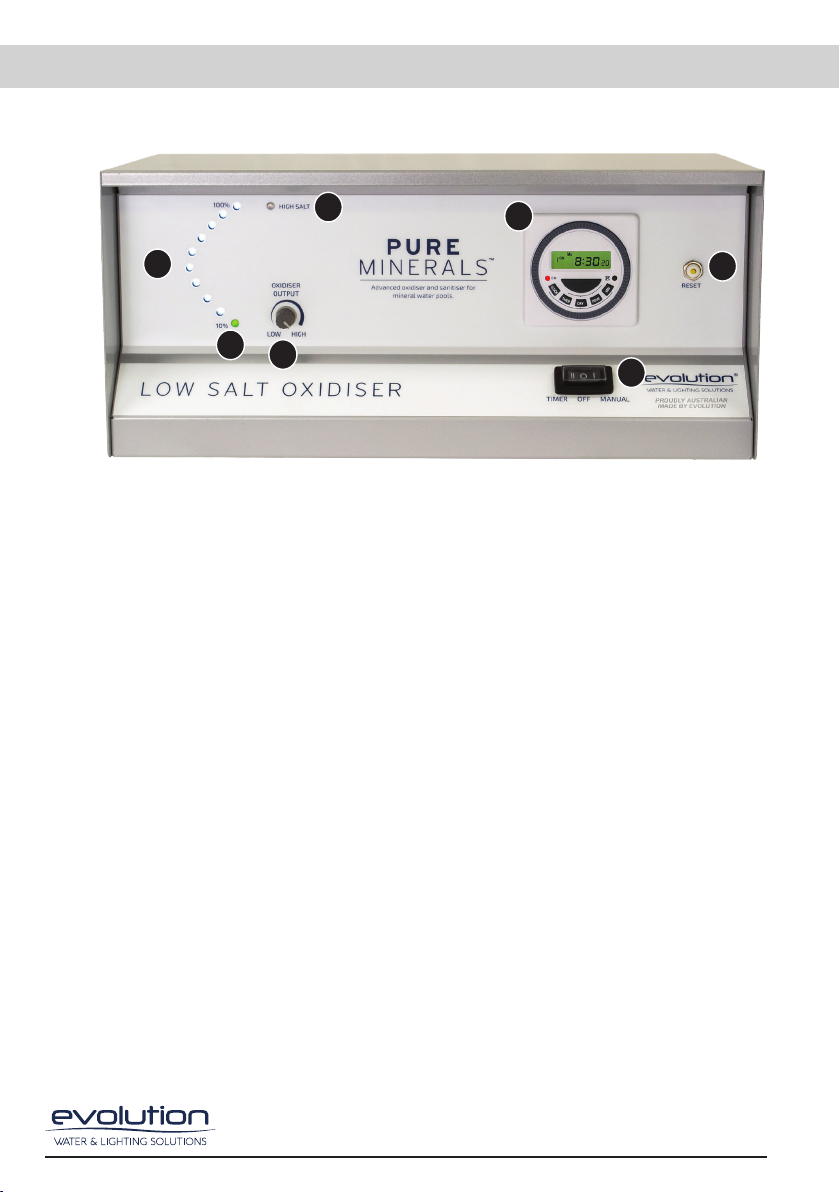
8.3 The transparent housing of the cell allows easy visual inspections, and with correct
water chemistry, the cell will only need cleaning approximately every 3-6 months. In
regions with hard water (high calcium levels), more frequent cleaning may be required.
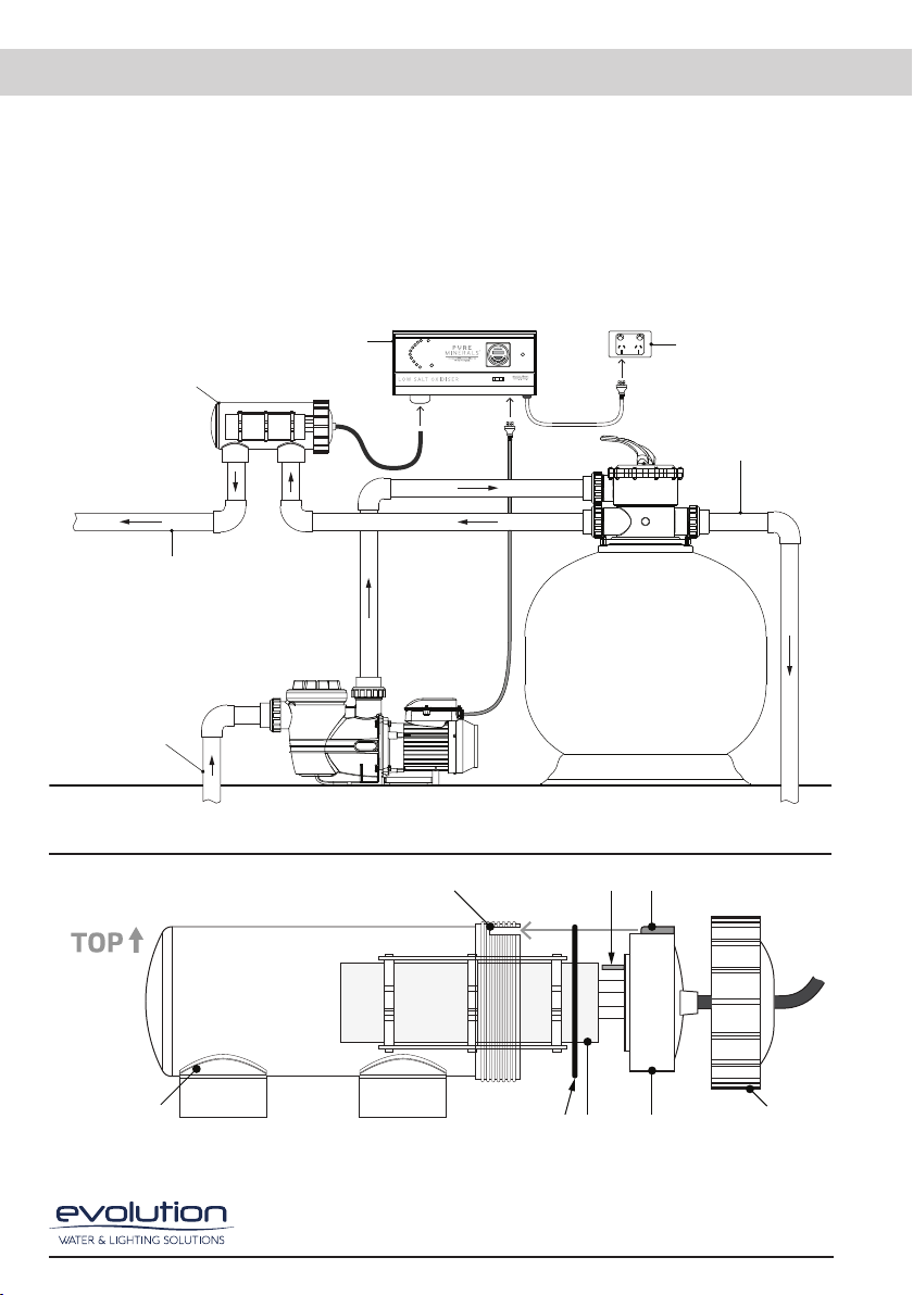
8.4 To clean the cell follow these instructions:
1. Turn off power to the Oxidiser and pump.
2. Remove the cell from the cell housing by loosening the cell collar and pulling the
cell out of the housing. If required, disconnect the cell cable wires at the junction box
underneath the power pack (these must be reconnected firmly and tightly).
3. With the cell removed, use a high-pressure hose nozzle to spray off as much loose
scale as possible. Do not use any sharp or metallic objects to remove scale, as this will
damage the cell.
4. If further cleaning is required, the cell needs to be cleaned in a mixture of 1 part
Hydrochloric Acid to 10 parts water. Mix the acid solution in a bucket or tube that will
fit the cell.
5. iWARNING: Chemical Hazard - When mixing acid with water, always add the
acid to the water, never add water to the acid. When using the acid, ensure to use
rubber gloves and appropriate eye protection and follow safety directions on the
Hydrochloric Acid label.
6. Place the cell into the cleaning solution submerging the plates and ensuring that
the cell head (Section 3.0 Fig. 2) does not contact the acid solution. Once the cell is
clean, remove it from the cleaning solution and rinse. Replace the cell into the housing
in the reverse manner to the steps above.
8.5 Only qualified electrical technicians should service the power pack. For the nearest
Evolution recommended service technician, please contact Evolution Water & Lighting
Solutions on 07 5565 0000 or email us at service@evolutionwls.com.au.

9
9.0 TROUBLESHOOTING
Fault/Problem Possible Cause Remedy
NO FLOW
All oxidiser output
LEDs ashing
Pump turned o. Ensure the pump is on.
Closed valve. Open valve.
Air in the system. Check all o-rings and grease.
Dirty lter. Clean or backwash lter.
Low water level. Fill up the pool.
Calcium build-up on
water probe sensor.
Clean probe in a mild hydrochloric
acid solution as per Page 9.
HIGH SALT
Red LED illuminated
Salinity level higher
than required.
No action is needed.
Let salinity level reduce over time.
NO LIGHTS
Circuit breaker tripped.
Reset circuit breaker. If it
trips again immediately call a
technician.
Mains power failure. Check switches and switchboard
circuit breaker.
LOW / NO OXIDISER
PRODUCTION
Oxidiser output too low. Increase oxidiser production, turn
oxidiser output clockwise.
Salinity level too low
(LED 1 ashing green).
Increase salinity to within 1,800
– 4,000ppm and check stabiliser
(Cyanuric) levels.
pH too high. Adjust pH between 7.2 – 7.6
Timer period too short. Increase running time.
High phosphate levels. Treat pool water with phosphate
remover.
Cell connections not secure. Check connections at junction
box under the unit.
ABNORMAL CALCIUM
BUILD-UP ON CELL
Calcium level in pool water is
extremely high or unbalanced
water chemistry.
Have water tested and balanced
as per Langlier Saturation Index.
Clean cell with mild HCl solution.
TIMER TIMES OUT
OF SYNC
Timer is not set correctly. Check setting procedure as per
Page 5.
Unit installed on o-peak tari. Adjust timer accordingly.
Timer / O / Manual switch not
selected correctly.
Make sure switch is selected
correctly, see Page 5.
OVER TEMPERATURE
(LED 1 ashing red
and amber)
Unit is installed in an
area where the ambient
temperature is extremely high.
Supply adequate cooling.
Install outside of the extreme
temperature area.

10
10.0 WARRANTY
10.1 The Evolution Low Salt Oxidiser is covered by a 3-year full warranty from the date of
purchase. The power pack and electrolytic cell are covered against defects in materials
and assembly from the date of purchase in a domestic application. All electrical or
mechanical failure due to faulty components will be repaired or replaced at no cost to
the owner, including labour. Warranty will not be covered without proof of purchase, so
keep the original purchase invoice in a safe place.
10.2 In field labour is limited to the Gold Coast city metropolitan area. Outside of these areas
the complete unit should be returned to Evolution Water & Lighting Solutions or one
of our warranty agents. Freight charges may apply and are entirely at the discretion
of Evolution Water & Lighting Solutions. Please contact us in regards to an authorised
warranty agent in your area.
10.3 The warranty will be void due to unfavourable environments and operating conditions
beyond the control of the manufacturer. These include but are not limited to: incorrect
power supply (must be 230V, 50Hz), the Low Salt Oxidiser connected to an ancillary
device such as a Variable Frequency Drive, wear and tear, water and insect damage,
extreme ambient temperatures or any other adverse situation that affects the unit. All
warranties onlyapply ifthe equipment is installed and operated in complete compliance
with the Installation and Operation Manual.
10.4 Evolution Low Salt Oxidisers and cells installed in a commercial situation are covered
by a 1-year warranty. Commercial situations include motels/hotels, health spas,
apartment/townhouse complexes and any location with an unusually high bather load
or abnormal conditions.
10.5 Evolution Water & Lighting Solutions will not accept liability for any consequential loss
or damage of any kind.
For all warranty enquiries, please do not hesitate to call 07 5565 0000 or email
Purchased from:
Purchase date:
Serial No:
Model No:
IMPORTANT
Please attach sales invoice/receipt here as a proof of purchase should warranty service
be required. Please keep warranty form and retain for records.

11

12
11.0 NOTES

13

Evolution Water and Lighting Solutions
1/33 Hinkler Drive, Highland Park QLD 4211, Australia +61 7 5565 0000
Unless otherwise indicated, copyright in the content of this document is the property of Evolution Water and
Lighting Solutions under Australian copyright law. Unless otherwise indicated, content may not be reproduced
or transmitted without our prior written permission.
© 2023 Evolution Water and Lighting Solutions. All rights reserved.
Table of contents
Other Evolution Accessories manuals