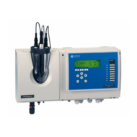
Evoqua WALLACE & TIERNAN MFC User manual

WALLACE & TIERNAN
®
MULTI-FUNCTION-CONTROLLER
MFC
from version V:2.00
INSTRUCTION MANUAL

2WT.050.580.000.DE.IM.0714
MFC
Please note
Original manual!

MFC Contents
3
Contents
1. Introduction 5
1.1 Documentation 5
2. General Safety Instructions 7
2.1 Intended Use 7
2.2 Conventions 8
2.3 General Principles 8
2.4 Notes for Operator and Operating Personnel 9
2.5 Guarantee Conditions 10
2.6 Personnel Selection and Qualification 11
2.7 Specific Operating Phases 11
2.8 Notes on Special Dangers 12
3. Description 13
3.1 Technical Data 13
3.2 Scope of supply 29
3.3 Description 31
4. Functions 41
4.1 General Information 41
4.2 Measurement inputs 46
4.3 Output Modules 70
4.4 Applications 71
4.5 Controller Function 77
4.6 Controller Outputs 92
4.7 Control Parameters 95
4.8 Alarms 102
4.9 Adaption 104
4.10 Interfaces 108

4WT.050.580.000.DE.IM.0714
Contents MFC
4.11 CAN interface 111
4.12 Special Features 114
5. Operation 115
5.1 Display and Operator Controls 115
5.2 Notes on Operation 120
5.3 Menu structure 122
5.4 Calibration 151
5.5 Errors 162
6. Installation 169
6.1 Transport and storage 169
6.2 Installation 170
6.3 Commissioning 174
6.4 Decommissioning 202
7. Maintenance 203
7.1 Maintenance Schedules 203
7.2 Maintaining DEPOLOX® 5 flow block assembly 205
7.3 Maintaining membrane sensors 210
7.4 Maintaining ORP electrode 210
7.5 Maintaining pH electrode 211
7.6 Maintaining fluoride electrode 211
7.7 Maintaining conductivity electrode 212
7.8 Replacing a fuse 213
7.9 Replacing the battery 214
8. Complete Devices, Retrofit Kits and Spare Parts 215
9. Wiring Diagrams 239
10. Certificates 247
11. Settings table 251
12. Index 263

MFC Introduction
1.
5
1. Introduction
1.1 Documentation
1.1.1 Target Groups
This operating manual provides the information for installation,
operating and maintenance personnel. It is required for operation
and maintenance of the device.
The operating manual is provided for the operating personnel. It
contains important information for safe and reliable, trouble-free
and economical operation of the device. Observance of this
information helps to prevent danger, lowers repair outlay, reduces
down-times,andalsoincreasesthereliabilityandservicelifeofthe
device.
The chapters on installation and maintenance are solely provided
for trained service personnel. These sections contain important
informationontheinstallation,configurationandcommissioningof
the device as well as information on its repair.

6WT.050.580.000.DE.IM.0714
Introduction MFC
1.

MFC General Safety Instructions
2.
7
2. General Safety Instructions
2.1 Intended Use
The MFC (Multi-Function-Controller) is exclusively designed for
measurement and control purposes for the treatment of waste
water, potable water and industrial water.
The MFC may only be used in buildings and under the operating
conditions described in the technical data.
The device is not designed for any application other than that
described in this manual –this is contrary to its intended use!
Compliance with the intended use of this device also includes
reading this operating manual and observance of all instructions
which it contains, particularly the safety instructions. Furthermore,
all inspection and maintenance work must be performed at the
prescribed intervals.
If the device is not employed in accordance with its intended use,
safe and reliable operation cannot be guaranteed.
The operator is solely responsible for any personal injury or
damagetopropertyresultingfromemploymentofthedevicewhich
is contrary to its intended use! The operator is obliged to keep the
device in proper working order.

8WT.050.580.000.DE.IM.0714
General Safety Instructions MFC
2.
2.2 Conventions
Note The following descriptions and symbols are used in this operating
manual to indicate hazards, mandatory instructions and notes:
2.3 General Principles
General Principles This device corresponds to the state of the art and recognised
technical safety regulations!
This device contains inherent hazards for personnel and
equipment! These hazards are related to live components or
incorrect dosing of chemicals.
Always observe the safety instructions and hazard notes!
Only use this device in accordance with its intended purpose!
Faults which can negatively affect safety must be remedied
immediately!
Picto-
gram Note Meaning
Danger! Immediate danger to life and limb!
If the situation is not handled
properly, death or serious injury
may be the result.
Warning! Danger to life and limb! If the
situation is not handled properly,
death or serious injury may be the
result.
Caution! If this warning is not observed,
medium or slight injury or damage
to the equipment may the result.
Warning! Electrical hazard.
Switch the unit / system off with
the emergency OFF / main
switch...
Please note These notes facilitate work with
the unit / system.

MFC General Safety Instructions
2.
9
2.4 Notes for Operator and Operating Personnel
Notes for the operator This operating manual and the technical documentation of the
installed device components must always be available at the
installation site!
Always observe any supplementary, generally valid legal
regulations or other binding rules and ensure their compliance!
These rules and regulations concern, for example:
•Worksafety
• Accident prevention
• Environmental protection
•Hygiene
• First aid
All personnel charged with installation, commissioning, operation,
maintenance and repair of the device must read and understand
this operating manual, in particular the safety instructions!
Never attempt to perform any modifications, extensions or
conversions on the device which could have an adverse affect on
safety without the written approval of the manufacturer!
Only use spare parts which have been approved by the
manufacturer.Thisisalwaysguaranteedwhenoriginalspareparts
are purchased.
Alwaysobservetheintervalsforregularmaintenanceorinspection
work which are either prescribed orstated in the operating manual.
The system must not be used with flammable liquids or dangerous
or toxic gases.

10 WT.050.580.000.DE.IM.0714
General Safety Instructions MFC
2.
Notes for operating personnel Always read the operating manual, in particular the safety
instructions, before you operate the device for the first time!
Never employ any working methods which could endanger safety!
Always comply with the prescribed values for sample water
admission pressure, connection voltage and ambient and
operating conditions!
Never deactivate any safety features!
During operation of the device there is the risk of unexpected
incorrect functions resulting from failure or errors of the control
system.
In the event of such safety-relevant changes in the operating
performance of the device, switch it off immediately and remedy
the fault or have it remedied immediately!
When the device is switched off, external voltage may still be
applied.
Always eliminate or have eliminated any leakage on the flow block
assembly immediately!
In the event of a fire always switch the device off with the external
main switch or the external main circuit breaker or fuse!
2.5 Guarantee Conditions
The following must be observed for compliance with guarantee
conditions:
• Installation, commissioning by Evoqua technicians or trained
and authorised specialised personnel, e.g. of contracted
companies
• Intended Use
• The operation parameters and settings must be met.
• The system may only be operated by trained personnel.
• A works journal must be kept.
• Use of approved calibration solutions
• The system should always be protected against frost.
• Execution of maintenance work by operating personnel
• Use of original spare parts
If any of the above conditions are not met, the guarantee is
revoked.

MFC General Safety Instructions
2.
11
2.6 Personnel Selection and Qualification
Only authorised personnel may operate or perform any work on
the device!
Only employ reliable, trained and instructed personnel!
Always clearly define competence of personnel for installation,
operation, maintenance and repair!
Assign responsibility. The operating personnel must be able to
refuse to act upon instructions of third parties which are contrary
to the safety regulations!
2.7 Specific Operating Phases
Normal operation Never employ any working methods which could affect safety!
Only run the device when the housing is closed!
Inspect the device at least once daily for externally visibledamage
and faults! Informthe responsible person/authority immediately of
any detected changes (including any changes in the operating
performance)!
In the event of malfunctions, always switch the device off
immediately! Have malfunctions remedied immediately!
Installation and
maintenance work Always perform installation or maintenance work in accordance
with this operating manual or the technical documentation for
installed device components!
Secure the device against activation during installation and
maintenance work!
Always retighten released screw connections!
Never use corrosive cleaning agents!
For cleaning only use a damp cloth.
Ensure safe disposal of agents and replaced parts in accordance
with environmental regulations!

12 WT.050.580.000.DE.IM.0714
General Safety Instructions MFC
2.
2.8 Notes on Special Dangers
Electrical power Only use original fuses with the prescribed current rating! In the
event of a fault in the electrical power supply, switch the device off
immediately!
Only qualified electricians or trained personnel supervised by a
qualifiedelectricianare permittedto perform any work on electrical
components in accordance with valid electrotechnical regulations.
If stipulated, disconnect all parts of the device from the power
supply before performing any inspection, maintenance or repair
work. Then first test the disconnected components to ensure they
do not carry any voltage.
Inspect/check the electrical system of the device regularly.
Remedy any faults immediately!
Connect disconnected cables in accordance with the wiring
diagram!
Agents and
chemical substances When handling agents and chemical substances always observe
the safety regulations valid for each product!
Always remove leaked agents immediately with a suitable binder
or wipe up with a cloth. Danger of slipping!
Always collect and dispose of agents or used cleaning material
separately and in accordance with valid national regulations!

MFC Description
3.
13
3. Description
3.1 Technical Data
3.1.1 MFC electronic module
Housing Dimensions (W x H x D): 320 x 270 x 175 mm
Weight: approx. 5 kg
Protection category: IP 66
Electronics Mains connection
• 200–240 V AC ± 10 %, 50–60 Hz, 30 VA,
Fuse 1A (T) Type: TR5
• 100–120 V AC ± 10 %, 50–60 Hz, 30 VA,
Fuse 1A (T) Type: TR5
• 24 V DC ± 20 %, 30 W, Fuse 2.5 A (T) Type: TR5
Insulation
• Overvoltage category 2
• Contamination level 2
Operating conditions
• Ambient temperature 0–50 °C
• Humidity < 80 %, non-condensing
• Environment No direct sunlight
• Atmospheric pressure 75–106 kPa
• max. altitude 2000 m
• Storage temperature -20 to +70 °C
• Noise emission <45 dB
Digital inputs 3 x for floating contact (< 100 Ohm)
Power supply though MFC
• D1: Sample water monitoring (freely selectable)
• D2: Freely selectable in menu
• D3: Freely selectable in menu

14 WT.050.580.000.DE.IM.0714
Description MFC
3.
Measurement inputs 1x Temperature input PT 1000 (0–50 °C) with sensor error display
(pre-calibrated)
1x Feedback input
Positioner position feedback
Potentiometer 1 kOhm or 5 kOhm
5xMeasuredvalueinput (electricallyisolatedupto50Vto ground)
for sensor measuring module plug-in cards
• 3 electrode cells for chlorine, chlorine dioxide or potassium
permanganate
• Membrane sensors for total chlorine (TC1), free chlorine
(FC1), chlorine dioxide (CD7, ozone (OZ7)
• pH value
• Redox potential
• Fluoride
• Conductivity
• mA/V input
Interfaces 1x RS232 for direct printer control or firmware update (not
electrically isolated)
1x RS485 for connection to:
• ChemWeb server
• OPC Server Data Access V2.0
• CMS Software 3.0
• SECO-S7
The RS485 interface is electrically isolated up to 50 V to ground
1x IRDA for remote calibration with the photometer P42 i-cal
(isolated)
Display and operating unit 1x Operating panel with 9 keys
8x Red LEDs for indication of operating conditions
1x Green LED for indication of the power supply
1x Graphic display
• Resolution 240 x 64 pixels
• Green background illumination

MFC Description
3.
15
Relay plug-in card 8x Relay outputs (two-way switch)
• Switching values
5 A, 250 V AC, 1250 VA max
5 A, 220 V DC, 150 W max
• UL/CSA-rating
5 A, 1/6 HP 125, 250 V AC
5 A, 30 V DC, 30 W max
1 A, 30 V DC – 0.24 A, 125 V DC
Storage temperature: -20 to +70 °C
Analog outputs plug-in card 4x Outputs (freely configurable)
• Output 0/4–20 mA
• Accuracy < 0.5 % FS
• Load max. can be switched over 1000 Ohm / 400 Ohm
• Temperature drift max. 0.2 % / 10 °C
• Load monitoring
• Electrically isolated up to 50 V to ground
Storage temperature: -20 to +70 °C
Calibration: pre-calibrated
Please note
All sensor measuring modules are electrically isolated to 50 V to
ground.
DES measuring module
3 electrode cell Sensor: 3 electrode cell
Principle of operation: Potentiostatic amperometry
Temperature drift max. 0.2 % / 10 K
Linearity error: < 0.1 %
Calibration: pre-calibrated
Upot cell voltage: 0 to +1000 mV
Upot accuracy: ± 20 mV
Upot temperature drift 0.5 % / 10 K
Cell current: -7 to 1000 µA

16 WT.050.580.000.DE.IM.0714
Description MFC
3.
DES module
Membrane sensors Sensor: 3 electrode sensor
membrane-covered
Principle of operation: Potentiostatic amperometry
Temperature drift max. 0.2 % / 10 K
Linearity error: < 0.1 %
Calibration: pre-calibrated
Input signal
(plug-in card): -7 to 1000 µA cell current
pH measuring module
for pH value Sensor input: pH single-rod electrode
Temperature drift max. 0.2 % / 10 K
Linearity error: < 0.1 %
Calibration: pre-calibrated
Input signal -1000 to +1000 mV
Input impedance: 1013 Ohm
mV measuring module
for Redox Sensor input: Redox single-rod electrode
Temperature drift max. 0.2 % / 10 K
Linearity error: < 0,1 %
Calibration: pre-calibrated
Input signal -1000 to +1000 mV
Input impedance: 1013 Ohm
mS measuring module
for conductivity Sensor input: LF325
Temperature measuring range: 0 to +50 °C
Temperature drift: < 0.2 %
Calibration: pre-calibrated
Linearity error: < 0.5 %
Measuring ranges: 2500 µS/cm,
10, 20, 50, 100, 200 mS/cm

MFC Description
3.
17
mA/V measuring module
for analog input Sensor input: mA signal or V signal
Temperature drift: max. 0.2 % / 10 K
Linearity error: < 0.1 %
Calibration: pre-calibrated
Measuring ranges: 0/4–20 mA (scalable) or
0–10 V (scalable)
F-measuring module
for fluoride Sensor input: Fluoride single-rod electrode
Calibration: pre-calibrated
Measuring ranges: 0.2 to 2.0 mg/l
0.5 to 5.0 mg/l
2.0 to 20.0 mg/l
Temperature drift: max. 0.2 % / 10 k
Linearity error: < 0.1 %
3.1.2 Flow block assembly DEPOLOX®5
Housing Dimensions (W x H x D): 215 x 375 x 155 mm
Weight: approx. 1.5 kg
Multi sensor Switching point: 21 l/h ± 3 l/h
Switching hysteresis: 2 l/h
Temperature sensor: Pt 1000
Measured variables Free chlorine, chlorine dioxide, ozone, potassium permanganate
Typical output signal approx. 20 µA/mg/l free chlorine
Measuring system Potentiostatic 3 electrode system
Max. measuring ranges 0 to 50 mg/l
Reference electrode Silver/Silver chloride/Potassium chloride solution
Working electrode PCBs
Other materials PVC, PMMA, ABS, ECTFE, PTFE, stainless steel, EPDM, FKM,
NBR
Cable length 650 mm
Electrolyte Potassium chloride solution, 3 mol

18 WT.050.580.000.DE.IM.0714
Description MFC
3.
Chemical analysis Photometric measuring process
Zero point calibration By stopping flow rate or dechlorinated sample water
typ. zero current approx. 1 µA
Response time T90:< 20 sec.
Influence of the pH value HOCI curve
Temperature compensation 0–50 °C
Storage temperature -10 °C to +50 °C (without electrolyte)
Volumetric flow control Flow rate: approx. 33 l/h (controlled)
Control range: 0.2 to 4.0 bar
Back-pressure: - non-pressurised version
(open drain)
- pressurised version 1.5 bar
Water quality swimming pool, potable, industrial and process water
Sample water Sample water temperature: max +50 °C
Conductivity min. 200 µS/cm
Service life Life of the electrolytes in operation approx. 6 months
Electrode service life in operation approx. 5 years
(reduced by poor water quality, e.g. sand, filth)
Connections Sample water: PVC hose 6 x 3 mm or
PE-hose 6 x 1 mm
Thread connection: G1/2" or NPT-1/4“

MFC Description
3.
19
3.1.3 Flow block assembly VariaSens
Housing Dimensions (W x H x D): 215 x 375 x 155 mm
Weight: approx. 1.5 kg
Connections Sample water: PVC hose 6 x 3 mm or
PE hose 6 x 1 mm
Thread connection: G1/2" or NPT-1/4“
Flow control valve Flow rate: approx. 33 l/h (controlled)
Control range: 0.2 to 4.0 bar
Back-pressure: - non-pressurised version
(open drain)
- pressurised version 1.5 bar
Sample water temperature max. +50 °C
Multi sensor Switching point: 21 l/h ± 3 l/h
Switching hysteresis: 2 l/h
Temperature sensor: Pt 1000
3.1.4 Y flow-through adapter
Y flow-through adapter pH/mV Back-pressure: non-pressurised/pressurised
Version (max. 6 bar)
Sample water temperature: max +50 °C
Y flow-through adapter fluoride Back-pressure: non-pressurised version
Sample water temperature: max +50 °C
Y flow-through adapter
conductivity Back-pressure pressurised version up to 6 bar
Sample water temperature: max +50 °C

20 WT.050.580.000.DE.IM.0714
Description MFC
3.
3.1.5 Electrodes and sensors
pH electrode Max. measuring range: pH 0–12
Operating temperature range: -5 to +80 °C
Storage temperature range: -5 to +30 °C
Sample water conductivity: 200 µS/cm – 200 mS/cm
Max. operating pressure: 6 bar
Redox electrode Max. measuring range: -1000 to +1000 mV
Operating temperature range: -10 to +80 °C
Storage temperature range: -5 to +30 °C
Sample water conductivity: 200 µS/cm – 200 mS/cm
Max. operating pressure: 6 bar
Fluoride electrode Max. measuring range: 0.2 to 20 mg/l
Operating temperature range: 0 to +80 °C
Storage temperature range: -5 to +30 °C
Sample water conductivity: 200 µS/cm – 200 mS/cm
Max. operating pressure: non-pressurised
Conductivity electrode Measuring system: 4 electrode system LF325
Principle of operation: 4 conductor measurement
Operating temperature range: -5 to +100 °C
Storage temperature range: -5 to +50 °C
Cell constant: 0.48 cm-1 ± 1.5 %
Max. operating pressure: 10 bar
Measuring ranges: 0.100 mS/cm to 200 mS/cm
Table of contents
Other Evoqua Controllers manuals
