manuals.online logo
Brands
  1. Home
  2. •
  3. Brands
  4. •
  5. Well
  6. •
  7. Controllers
  8. •
  9. Well AVR-REL-THUNDER500-WL User manual

Well AVR-REL-THUNDER500-WL User manual

INSTRUCTION MANUAL
AUTOMATIC VOLTAGE REGULATOR
Thank you for choosing WELL. Please read carefully the following instructions and keep them within reach.
Reorder No: AVR-REL-THUNDER500-WL, AVR-REL-THUNDER-1000-WL
1. Important Safety Instructions
This AVR has been designed to provide all the necessary safety conditions needed to protect electronic office
equipment including information systems. In case of any questions, refer to your authorized technical service
representative.
- In order to avoid any damage to the equipment, it is advised to trans- port it in its own packing.
- In the event of sudden temperature changes such as from cold to the normal working temperature, mist can form
inside the AVR. It is absolutely essential that the AVR be dry before switching it on. Due to this reason wait for at
least 2 hours before operating it.
- Once it’s dry, make sure you observe all the conditions in the environment section of the technical specifications
table, before introducing it into the circuit.
Earth cable should be chosen concerning the current capacity. All units’ earth connections, which are connected to
AVR, should be done with this earth cable.
Without earth connection or unproved earth connected units are dangerous for user health and have high risk of
electronic circuit board faults. When installing the AVR to use cable with improper diameter can be dangerous for
user’s health and safety of the unit.
- Place all the cables in a proper place so that they are not stepped on or get caught into people’s feet. Before connecting
the AVR to the circuit makes sure you carefully read all the instructions and warnings in the “Installation” section of
this manual.
- Don’t drop any foreign materials (like clips, nails etc...) into the equipment.
- In emergencies (damage to the cabinet, front panel, or mains connections, splashing of liquid dropping of any foreign
materials into the equipment) switch-off the AVR, pull out the plug and inform the authorized service center.
- Do not connect any loads to the AVR, which exceed its power range.
- When input distortion or resistance is too high, AVR may not work properly.
- Keep the packing for maintenance or moving.
- Wiring must be tight, to prevent falling off and oxidation.
The AVR can only be repaired by the authorized technical service personnel. Any attempt to open and to repair by the
user on his own could prove to be dangerous.
Intended for installation in a controlled environment.
a) The controlled environment should accord with the requirement of the specification.
b) Do not install or operate your AVR in or near water.
c) Do not place AVR on an unstable cart, stand or table.
d) Do not place AVR under direct sunlight or close to heat emitting sources.
e) Do not place AVR power cord in any area where it may get damaged by heavy objects.
Placing magnetic storage media on top of the AVR may result in data corruption.
Special precautions:
When the AVR input comes from a generator:
a) Output power capacity must be higher than the AVR rating, or the AVR and generator may not work properly;
b) Output frequency of generator must be in range of 48Hz~52Hz or Hz~62Hz, and waveform must be sine
wave, otherwise the AVR and generator may not work properly.
2. Specifications
Model No.
AVR-REL-THUNDER500-WL
AVR-REL-THUNDER1000-WL
Capacity
300W
600W
AC Input Voltage
144V~264V (±3V)
144V~264V (±3V)
Input Frequency
45Hz~65Hz
45Hz~65Hz
AC Output Voltage
230V
230V
Output Frequency
Synchronized with mains
frequency
Synchronized with mains
frequency
Remarks:
•Single phase only.
•We reserve the right to change specifications or discontinue models without notice.
3. Before Installation
Each AVR was tested 100% before shipment, check if the AVR has been subjected to any damage after unpacking it
according to the following steps:
A. Contents
Delivered pack includes:
AVR 1 piece
User’s manual 1 piece
B. Visual observation
a) Check the name plate to verify the rated capacity is according to your purchase order.
b) Make sure appearance of the AVR is not damaged. If you notice any damage, contact the transport firm and
the authorized dealer.
Do not try to operate the AVR in this situation!
Do not try to repair the AVR by yourself!
4. Introduction to the Regulator
Familiarize yourself with the various features and facilities by studying the two diagrams below to obtain maximum
benefit from the regulator.
a. Front of the Regulator
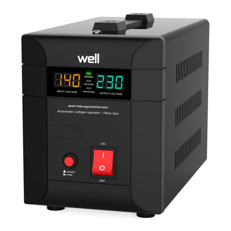
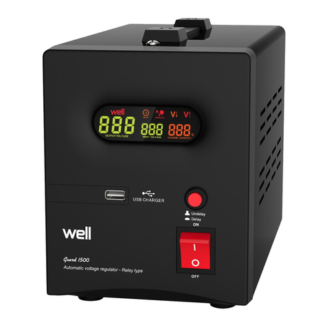
1. Input Voltage Display
2. Output Voltage Display
3. Delay Button
4. Green LED Light (Indicator for “POWER ON”)
5. Yellow LED Light (Indicator for “DELAYING”)
6. Red LED Light (Indicator for “PROTECTING”)
Symbol on POWER SWITCH:
“-” : power on
“O” : power off
Output Precision
+4%, -9% (without load)
Distortion
<3% (compare to input wave
form)
<3% (compare to input wave
form)
Power Factor
0.6
0.6
Efficiency
>0.95
>0.95
Operating
Temperature
-10˚C~40˚C
-10˚C~40˚C
Operating Humidity
0~90%(Non-condensing)
Noise
≤56dB (full load, distance at 1
meter)
≤56dB (full load, distance at 1
meter)
Delay Time
6/180 seconds selectable
Protection
Output Low Voltage
Output High Voltage
Overheat, Short Circuit (output)
Output Low Voltage
Output High Voltage
Overheat, Short Circuit (output)
Certification
CE (EMC+LVD)
CE (EMC+LVD)
b. Back and Side of the Regulator
7. Hanger
8. Power Switch
9. Input Cable
10. Outlet
5. Operation of the AVR
a. Connect the Electrical Appliances to Regulator
• Make sure all appliances are turned "OFF", and put power switch of AVR to “OFF” position.
• Plug the AC mains cord of the appliances into the output socket of AVR, ensuring that the total starting power needed
does not exceed the rated maximum output power of the AVR.
b. Connect Regulator to Electrical Mains
Plug the AC mains cord to wall mains socket.
c. Switch on the regulator
Switch the power "ON"
• Put the power switch to "ON" position,the yellow LED will illuminate and blink. At the same time, the digital
display will show the elapsing delay time. Generally delay time is set at 6~10 seconds.
• Then the yellow LED lights off and the green will illuminate.
• The digital display will show output voltage supplying to appliances connected to the regulator.
• Switch "ON" the appliances one by one.
In Case of Power Failure:
• Switch "OFF" the regulator and all the appliances.
• Repeat above steps when power is restored.
d. Display of Input Voltage and Output Voltage
•The digital display will show the input voltage and output voltage after the AVR switched on.
e. LED Operation
• When the Green LED is "ON", it indicates Power ON and also that the input voltage and output voltage is normal,
the AVR is working.
• When the Yellow LED is “ON” and flash, it indicates that the regulator is in a delay status, the output will be delayed.
• When the Red LED is "ON" and flash, it indicates the regulator is in a protection status.
f. Delay Operation
• This model is designed with a delay feature to protect appliances with compressors which should not be switched on
immediately after being switched off.
• The delay time is generally set at from 6/180 seconds. Please select delay or undelay before switch on the AVR.
• When delay time has elapsed, delay LED will switch "OFF" and display will indicate the AC output voltage.
g. Integrated Automatic Protection Circuit (IAPC)
• This model is equipped with a specially designed INTEGRATED
AUTOMATIC PROTECTION CIRCUIT.
• This very specialized and unique circuitry is now redesigned to automatically cut off the input voltage whenever the
input voltage is above the input voltage range, rendering full and comprehensive protection to the regulator and
connected appliances.
• When the input voltage returns to within Low and Normal ranges, the IAPC will automatically switch the regulator
back "ON" and also restore power to all connected appliances.
h. Temperature Protection
• This AVR is equipped with a unique Temperature Protection Circuit designed to protect the transformer, giving you
longer and satisfactory use of the Regulator.
• If the internal temperature reaches the limit or above, the output power supply will cut "OFF" automatically. There
is no number to be shown in the display.
• When the internal temperature returns to normal range, output power will be restored. After the delay time, the
display will indicate output voltage.
i. High Output Voltage Protection
• This AVR is built in with a very specialized feature HIGH OUTPUT VOLTAGE PROTECTION CIRCUIT.
• This special and unique circuitry is designed to protect connected appliances whenever the output voltage is higher
than the normal range.
• If the output voltage is over the normal range, the output power supply will cut "OFF" automatically and the display
will show "H". At the same time, the Red LED blinks.
• Once the input city power returns to normal range, the AVR will restore the output
j. Low Output Voltage Protection
• When the output voltage is below the normal range, the output will be cut “OFF” automatically and the display will
show “L”. At the same time, the Red LED blinks
• Once the input city power returns to normal range, the AVR will restore the output to the loads.
k. Short circuit protection.
• In case of a short circuit or overload, the power switch will trip off the input power supply automatically.
• Please check if the AVR is overloaded, if so, please remove some loads.
• Please check if the appliances are short circuit, if so, please disconnect the appliances.
6. Placement
For safety and better performance and longer lifespan, please handle and place the AVR according to the follow
instructions:
a. Moving
a) Cut off input; remove all wires connected to the AVR
b) Do not move the AVR upside down
c) Rough handling is prohibited
b. Environmental
Keep away from unstable base or sources of excessive vibration.
Do not place the AVR under direct sunlight or excessive humidity.
Keep away from fire, heat sources.
Keep the AVR in well ventilated place. Leave at least a distance of 10 cm between the AVR and the walls in order to
maintain adequate air-flow.
Operating Temperature: -10˚C~40˚C
Operating Humidity: 0~90% (Non-condensing)
Keep away from corrosive gas or fluid.
Install the AVR in a cool, dry, clean place – away from windows, dust, moisture and cold. To prevent fire or
electrical shock, do not expose this unit to rain or water.
7. Maintenances
This AVR is basically maintenance free! But regular maintenance can extend the lifespan of AVR by the following
steps:
Regular inspection
Shut down the AVR completely
Use cotton cloth and detergent to clean the body and ventilation holes.
Check all the terminals, replace the abnormal one with that of the same specification.
Extraordinary inspection
When malfunction occurs, or the AVR is abnormal, please measure and check the parameters, refer to the authorized
dealer if needed.
In thunder and lightning or rainy season, Extraordinary Inspection should be executed to prevent malfunction.
Maintenance should not be operated when AVR is working.
8. Other
This user’s manual is only for E series IC controlled smart automatic voltage regulators.
This AVR is designed and made by strict standards and quality control system for common use, but if apply to purposes
may cause any dangerous to human or other lives, include but not limited to the following case, please refer to our
company:
a) Apply to traffic system;
b) Apply to medical purpose;
c) Apply to nuclear, power system;
d) Apply to aviation and aerospace;
e) Apply to all kinds of safety devices;
f) Other special usages.
Waste electrical and electronic equipment are a special waste category, collection,
storage, transport, treatment and recycling are important because they can avoid
environmental pollution and are harmful to health. Submitting waste electrical and
electronic equipment to special collection centers makes the waste to be recycled
properly and protecting the environment. Do not forget! Each electric appliance that
arrives at the landfill, the field, pollutes the environment!
Importer & distributor:
SC VITACOM ELECTRONICS SRL
CIF: RO 214527
Tel. 0264-438401*
[email protected], www.vitacom.ro

This manual suits for next models

1

Other Well Controllers manuals

Well RC-AC-HOMY-WL User manual

Well

Well RC-AC-HOMY-WL User manual

Well AVR-SRV-PERF1000WE-WL User manual

Well

Well AVR-SRV-PERF1000WE-WL User manual

Well AVR-SRV-SPRY500BK-WL User manual

Well

Well AVR-SRV-SPRY500BK-WL User manual

Well AVR-REL-GUARD1000-WL User manual

Well

Well AVR-REL-GUARD1000-WL User manual

Well AVR-SRV-XTREME 500-WL User manual

Well

Well AVR-SRV-XTREME 500-WL User manual

Well AVR-REL-SLIMPOWER500-WL User manual

Well

Well AVR-REL-SLIMPOWER500-WL User manual

Well AVR-REL-POWERUP500-WL User manual

Well

Well AVR-REL-POWERUP500-WL User manual

Well AVR-TRC-AGILE-1000-WL User manual

Well

Well AVR-TRC-AGILE-1000-WL User manual

Well AVR-REL-500-WL User manual

Well

Well AVR-REL-500-WL User manual

Popular Controllers manuals by other brands

Zennio MAXinBOX FANCOIL 2CH2P quick start guide

Zennio

Zennio MAXinBOX FANCOIL 2CH2P quick start guide

Azbil SDC45 user manual

Azbil

Azbil SDC45 user manual

Parker Sporlan S3C Quick reference guide

Parker

Parker Sporlan S3C Quick reference guide

Motoman XRC 2001 Concurrent I/O and Parameter Manual

Motoman

Motoman XRC 2001 Concurrent I/O and Parameter Manual

Pilz PNOZmulti PNOZ mmc3p manual

Pilz

Pilz PNOZmulti PNOZ mmc3p manual

YASKAWA MOTOMAN DX100 Operator's manual

YASKAWA

YASKAWA MOTOMAN DX100 Operator's manual

Apollo AIM-4SL Hardware manual

Apollo

Apollo AIM-4SL Hardware manual

Unitronics Vision V130-J-TA24 installation guide

Unitronics

Unitronics Vision V130-J-TA24 installation guide

Resource Data Management PR0750-TDB Installation & user guide

Resource Data Management

Resource Data Management PR0750-TDB Installation & user guide

HANGZHOU WORLDE MUSIC ELECTRONIC KX61/76/88HC user manual

HANGZHOU WORLDE MUSIC ELECTRONIC

HANGZHOU WORLDE MUSIC ELECTRONIC KX61/76/88HC user manual

Rockwell Automation Samsung NX70 user manual

Rockwell Automation

Rockwell Automation Samsung NX70 user manual

Adaptec AAR-2420SA Read me

Adaptec

Adaptec AAR-2420SA Read me

GE 90-30 PLC Installation and Hardware Manual

GE

GE 90-30 PLC Installation and Hardware Manual

Prolon VC2000 Installation and startup guide

Prolon

Prolon VC2000 Installation and startup guide

Danfoss AME 610 instructions

Danfoss

Danfoss AME 610 instructions

Solarwize RSC-PV1230 user manual

Solarwize

Solarwize RSC-PV1230 user manual

Rain Bird ESP-LX manual

Rain Bird

Rain Bird ESP-LX manual

Siemens N 562/11 Technical product information

Siemens

Siemens N 562/11 Technical product information

manuals.online logo
manuals.online logoBrands
  • About & Mission
  • Contact us
  • Privacy Policy
  • Terms and Conditions

Copyright 2025 Manuals.Online. All Rights Reserved.