EVS GFS010 Instruction sheet

INSTALLATION &
CONFIGURATION
MANUAL
GFS010 – HFS010 – SFS010
3GB/S, HD AND SD BASIC FRAME
SYNCHRONIZER

INSTALLATION AND CONFIGURATION MANUAL
GFS010
–
HFS010
–
SFS010
Copyright
EVS Broadcast Equipment S.A. – Copyright © 2001 – 2021. All rights reserved.
Disclaimer
The information in this manual is furnished for informational use only and subject to change
without notice. While every effort has been made to ensure that the information contained in
this user manual is accurate, up-to-date and reliable, EVS Broadcast Equipment cannot be held
responsible for inaccuracies or errors that may appear in this publication.
Improvement Requests
Your comments will help us improve the quality of the user documentation. Do not hesitate to
send improvement requests, or report any error or inaccuracy on this user manual by e-mail to
Regional Contacts
The address and phone number of the EVS headquarters are usually mentioned in the Help >
About menu in the user interface.
You will find the full list of addresses and phone numbers of local offices either at the end of this
user manual (for manuals on hardware products) or on the EVS website on the following page:
http://www.evs.com/contacts.
User Manuals on EVS Website
The latest version of Media Infrastructure manuals are available at: https://mi-sftp.evs.com/
The user manuals for other EVS products can be found at the EVS download center, on the
following webpage: https://www.evs.com/en/download-area.

EVS Broadcast E
q
ui
p
ment SA
1
WARNING: TO REDUCE THE RISK OF FIRE OR
ELECTRICAL SHOCK, DO NOT EXPOSE THIS
APPLIANCE TO RAIN OR MOISTURE
●ALWAYS disconnect your entire system from the AC mains before cleaning any component. The product
frame (SFR18 or SFR04) must be terminated with three-conductor AC mains power cord that includes an
earth ground connection. To prevent shock hazard, all three connections must always be used.
●NEVER use flammable or combustible chemicals for cleaning components.
●NEVER operate this product if any cover is removed.
●NEVER wet the inside of this product with any liquid.
●NEVER pour or spill liquids directly onto this unit.
●NEVER block airflow through ventilation slots.
●NEVER bypass any fuse.
●NEVER replace any fuse with a value or type other than those specified.
●NEVER attempt to repair this product. If a problem occurs, contact your local EVS distributor.
●NEVER expose this product to extremely high or low temperatures.
●NEVER operate this product in an explosive atmosphere.
Warranty: EVS warrants their products according to the warranty policy as described in the general terms.
That means that EVS Broadcast Equipment SA can only warrant the products as long as the serial numbers
are not removed.
Copyright © 2001 – 2021 EVS Broadcast Equipment SA
Date created: 19-11-2009
Date last revised: 19-04-2013
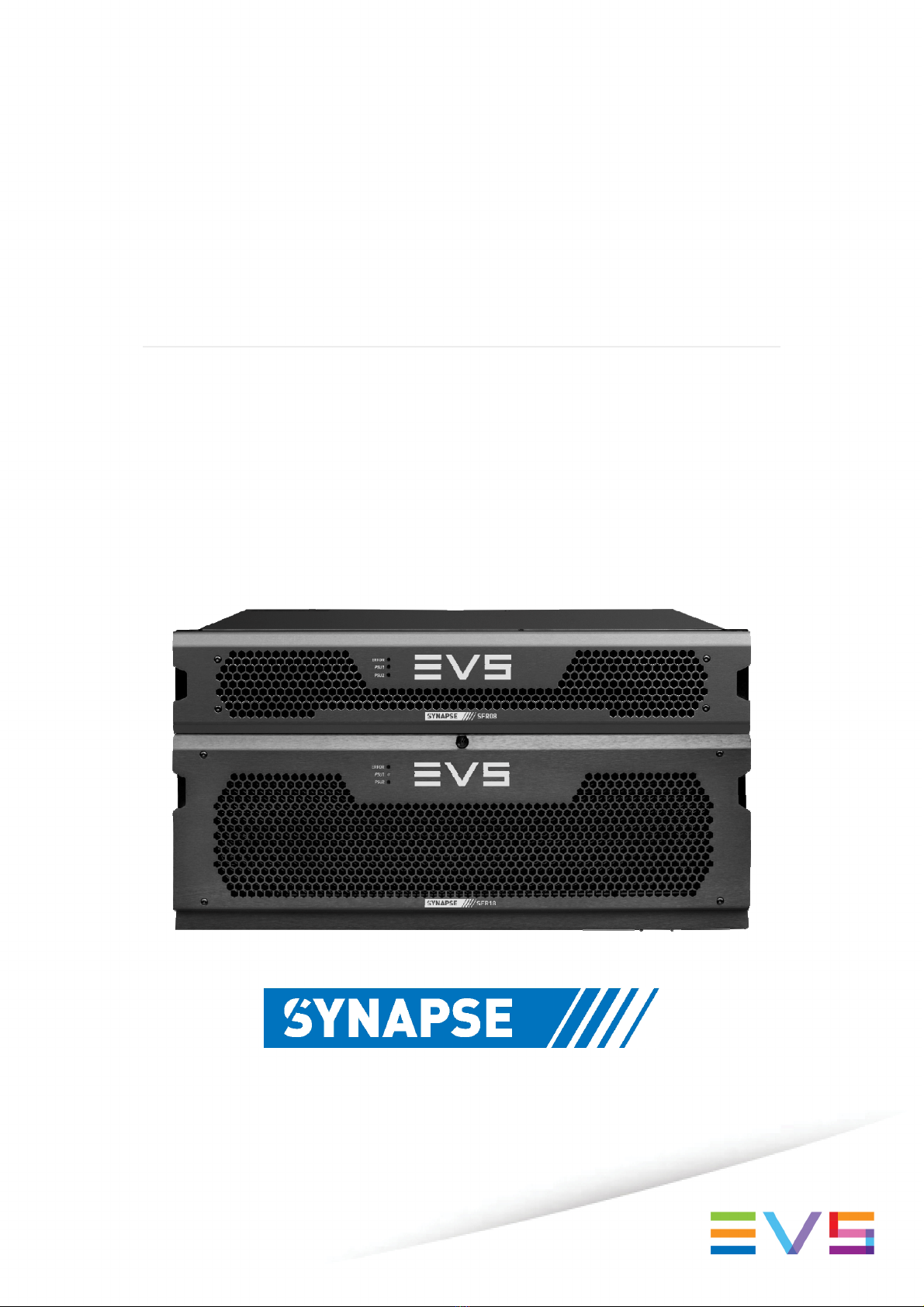
EVS, the EVS logo and Synapse are trademarks of EVS Broadcast Equipment SA
This product complies with the requirements of the product family standards for audio, video, audio-visual
entertainment lighting control apparatus for professional use as mentioned below.
EN60950
EN55103-1: 1996
EN55103-2: 1996
Safety
Emission
Immunity
EVS Broadcast Equipment
GFS010 / HFS010 / SFS010
Tested To Comply
With FCC Standards
FOR HOME OR OFFICE USE
This device complies with part 15 of the FCC Rules
Operation is subject to the following two conditions:
(1) This device may cause harmful interference, and
(2) This device must accept any interference received, including
interference that may cause undesired operation.

INSTALLATION AND CONFIGURATION MANUAL
GFS010
–
HFS010
–
SFS010
2
Table of Contents
Table of Contents 2
Introduction to Synapse 5
An Introduction to Synapse 5
Local Control Panel 5
Remote Control Capabilities 5
!5
Unpacking and Placement 6
Unpacking 6
Placing the card 6
A Quick Start 7
When Powering-up 7
Changing settings and parameters 7
Front Panel Control 7
Example of changing parameters using front panel control 8
Synapse Cortex Software 9
Menu Structure Example 9
The GFS-HFS-SFS010 Card 10
Introduction 10
Features 10
Applications 10
Block schematic 11
Settings Menu 12
Introduction 12
IO-Ctrl 12
IO_Prst_Act 12
IO_Prst_Edit 12
#Inp_SelA 12
#Out-Frmt 12
#IO-Map 13
#V-delay 13
#H-delay 13
#Freeze_A 13
Delay-Status 13
Lock-Mode 13
Ref-Type 14
P60-P50_Sync 14
ANC_BlankA 14
Freeze_Mode 14
PrstEditView 14
PatternSpeed 14
Input_loss_A 14
Timecode_Inp 15
VITC_Ln_In 15
VITC_Ln_Ctrl 15
VITC_Ln_625 15
VITC_Ln_525 15
VITC_Ln_Dup 15
Ins_CtrlA 15
Ins_Prst_ActA 15
Ins_Prst_EditA 16
#VI-InsertA 16
#VI-DataA 16
#WSS-InsertA 16
#WSS-StndA 16
#WSS-ExtndA 16
#VI-DataA 16
#S2016-InsertA 16
#S2016-DataA 16
#OSD-StyleA 17
#OSD-TextA 17

EVS Broadcast E
q
ui
p
ment SA
3
GainA 17
R-GainA 17
G-GainA 17
B-GainA 17
BlackA 17
R-BlackA 17
G-BlackA 17
B-BlackA 17
CVBS-Hue 17
Audio-Phase 18
AudioStatusBits 18
emb_aud_hand_A 18
Audio_Ctrl 18
Audio_Prst_act 19
Audio_Prst_Edit 19
#Emb-AB-Mode 19
#EmbA_Grp 19
#EmbA1_Inp ~ #EmbA4_Inp 19
#EmbB_Grp 19
#EmbB1_Inp ~ #EmbB4_Inp 19
#Emb-CD-Mode 20
#EmbC_Grp 20
#EmbC1_Inp ~ #EmbC4_Inp 20
#EmbD_Grp 20
#EmbD1_Inp ~ #EmbD4_Inp 20
GPI-Ctrl 20
GPI_1 ~ GPI_5 21
IP_Conf0 21
mIP0 21
mNM0 21
mGW0 21
NetwPrefix0 21
Status Menu 22
Introduction 22
sInp1 22
sInp1_VI 22
sInp1_WSS-Stnd 23
sInp1_WSS-Extd 23
sInp1_S2016 24
sInp1-Map 24
IODelayA 24
SwitchLnA 24
SwitchLn_LenA 24
SwitchLn_PosA 24
FunctionA 24
Ref 24
GPI 25
GPIA 25
GPIB 25
GPIC 25
OutputA-Map 25
IP_Addr0 25
MAC0 25
IP0 25
NM0 25
GW0 25
Events Menu 26
Introduction 26
What is the Goal of an event? 26
Events 26
Announcements 26
Input_A 26
Input_B 26
Ref-Status 26
What information is available in an event? 26
The Message String 27
The Tag 27
Defining Tags 27
The Priority 27
The Address 27

INSTALLATION AND CONFIGURATION MANUAL
GFS010
–
HFS010
–
SFS010
4
LED Indication 28
Error LED 28
Input_A LED 28
Input_B LED 28
ANC Data LED 28
Reference LED 28
Data Error LED 28
Connection LED 28
Error LED 28
Block Schematic 29
Connector Panels 30
GPI pinning 30
Appendix 1 31
Card dip-switches for BHX and fiber configuration 31
Using BPH17 with fiber I/O 31
Using BHX17b 31
Appendix 2 33
GPI’s explained 33
GPI pools 33
binary mode or priority mode 33
Example 1 33
Example 2 34
Example 3 34
GNU Public License version 2 36

EVS Broadcast E
q
ui
p
ment SA
5
1 Introduction to Synapse
An Introduction to
Synapse
Synapse is a modular system designed for the broadcast industry.
High density, intuitive operation and high quality processing are
key features of this system. Synapse offers a full range of converters
and processing modules. Please visit the EVS Broadcast Equipment
SA Website at http://www.evs.com to obtain the latest information
on our new products and updates.
Local Control
Panel
The local control panel gives access to all adjustable parameters and
provides status information for any of the cards in the Synapse
frame, including the Synapse rack controller. The local control
panel is also used to back-up and restore card settings. Please refer
to the RRC18, RRC10, RRC04, RRS18 and RRS04 manuals for a
detailed description of the local control panel, the way to set-up
remote control over IP and for frame related settings and status
information.
Remote Control
Capabilities
The remote control options are explained in the rack controller
(RRC18/RRC10/RRC04/RRS18/RRS04) manual. The method of
connection to a computer using Ethernet is described in the
RRC/RRS manual.
! CHECK-OUT: “SYNAPSE CORTEX” SOFTWARE
WILL INCREASE SYSTEM FLEXIBILITY OF ONE OR
MORE SYNAPSE FRAMES
Although not required to use Cortex with a Synapse frame, you are
strongly advised to use a remote personal computer or laptop PC
with Synapse Cortex installed, as this increases the ease of use and
understandin
g
of the modules.

INSTALLATION AND CONFIGURATION MANUAL
GFS010
–
HFS010
–
SFS010
6
2 Unpacking and Placement
Unpacking The EVS Synapse card must be unpacked in an anti-static
environment. Care must be taken NOT to touch components on the
card – always handle the card carefully by the edges. The card must
be stored and shipped in anti-static packaging. Ensuring that these
precautions are followed will prevent premature failure from
components mounted on the board.
Placing the card The Synapse card can be placed vertically in an SFR18 frame or
horizontally in an SFR04 and SFR08 frame. Locate the two guide
slots to be used, slide in the mounted circuit board, and push it
firmly to locate the connectors.
Correct insertion of card is essential as a card that is not located
properl
y
ma
y
show valid indicators, but does not function correctl
y
.
NOTE: On power up all LED’s will light for a few seconds, this is
the time it takes to initialise the card.
NOTE: Please check appendix 1
b
efore connectin
g
an
y
backpanel!

EVS Broadcast E
q
ui
p
ment SA
7
3 A Quick Start
When Powering-
up
On powering up the Synapse frame, the card set will use basic data
and default initialisation settings. All LED’s will light during this
process. After initialisation, several LED’s will remain lit – the
exact number and configuration is dependant upon the number of
inputs connected and the status of the inputs.
Changing settings
and parameters
The front panel controls or the Synapse Cortex can be used to
change settings. An overview of the settings can be found in chapter
5, 6 and 7 of this manual.
Front Panel
Control
Front Panel Display and Cursor
Settings are displayed and changed as follows;
Use the cursor ‘arrows’ on the front panel to select the menu and
parameter to be displayed and/or changed.
Press ►To
g
o forward throu
g
h the menu structure.
Press ◄To
g
o back throu
g
h the menu structure.
Press ▲To move up within a menu or increase the value of
a parameter.
Press ▼To move down through a menu or decrease the
value of a parameter.
NOTE: Whilst editing a setting, pressing ►twice will reset the
value to its default.
[No Alarms]

INSTALLATION AND CONFIGURATION MANUAL
GFS010
–
HFS010
–
SFS010
8
Example of
changing
parameters using
front panel control
With the display as shown below
Pressing the ►selects the SFS10 in frame slot 01.
The display changes to indicate that the SFS10 has been selected. In
this example the Settings menu item is indicated.
Pressing the ►selects the menu item shown, in this example
Settings.
(Pressing ▲or ▼will change to a different menu eg Status,
Events).
The display changes to indicate that the SFS10 Settings menu
item SDI-Format has been selected and shows that it current
setting is Auto.
Pressing the ►selects the settings item shown, in this example
SDI-Format.
(Pressing ▲or ▼will change to a different setting, eg Mode, H-
Delay).
The display changes to indicate that the SFS10 Edit Setting
menu item SDI-Format has been selected.
To edit the setting of the menu item press ▲or ▼.
All menu items can be monitored and/or changed in this way.
Chan
g
in
g
a settin
g
has an immediate effect.
RRC18 [Select Card]
>S01=SFS10
SFS10 [Select Menu]
>Settings
SFS10 [Settings]
>SDI-Format=Auto
SFS10 Edit Setting]
SDI-Format>Auto

EVS Broadcast E
q
ui
p
ment SA
9
Synapse Cortex
Software
Synapse Cortex can be used to change the settings of Synapse
modules from a PC, either locally or remotely. The software enables
communication based on TCP/IP between the Setup PC and
Synapse frames/modules.
Each Synapse frame is addressed through its rack controller’s
unique IP address, giving access to each module, its menus and
adjustment items. Synapse Cortex has access to data contained
within the Synapse module and displays it on a GUI. The software
has an intuitive structure following that of the module that it is
controlling.
For operation of S
y
napse Cortex, please refer to the Cortex manual.
Menu Structure
Example
Slot Module Item Paramete
r
Settin
g
▲
▲
S02 Identit
y
▲▲
S01 SFS10
►Set-
tings
►
Standard_dig ►Auto
▼▼▼▼
S00 RRC18 Status Mode 625
▼▼▼
Events Ref-Input 525
▼
H-Delay
▼
▼
NOTE: Further information about Front Panel Control and
Synapse Cortex can be obtained from the RRC and RRS operational
manuals and the Cortex help files.

INSTALLATION AND CONFIGURATION MANUAL
GFS010
–
HFS010
–
SFS010
10
4 The GFS-HFS-SFS010 Card
Introduction The GFS010, HFS010 and SFS010 are frame synchronizers with 16
channel audio transparency and color correcting capabilities.
The GFS010 is compatible with 270Mb/s, 1.5Gb/s and 3Gb/s for
full 1080p/50 or 1080p/59.94 use. The HFS010 is compatible with
SD-SDI (270Mb/s) and HD-SDI (1.5Gb/s) and can be future
upgraded to 3Gb/s compatibility. The SFS010 is limited to 270Mb/s
onl
y
but can also be up
g
raded to HD or even 3Gb/s.
Features
1 SDI input
Compatible with the following input formats (auto selecting)
(1080p only for GFS010):
1080p/59.94
1080p/50
1080i/59.94
1080i/50
1080p/29.97
1080p25
1080p24
720p/59.94
720p50
SD525
SD625
Color corrector
Transparent for 16 channels of embedded audio
Video proc-amp (Y and C control)
Hue control for NTSC inputs
Locks to a Bi-Level or a Tri-level sync, or to an SDI input.
Full control and status monitoring through the front panel of the
SFR04/SFR08/SFR18 frame and the Ethernet port (ACP)
Frame sync with output phase control in Lines and pixels with
respect to reference
NOTE: The frame synchronizer works at best if the inputs are
switched according the SMPTE guidelines described in RP168.
This ensures that not only the picture but also the ancillary data
remains correct. The frame synchronizer however can handle
complete asynchronous switching at the input.
To ensure correct operation the F-delay of the card needs to be 1 or
higher so there is enough time to mask the error.
Applications Transmission output frame synchronizer with backup input.
General purpose post router autophaser.

EVS Broadcast E
q
ui
p
ment SA
11
Block schematic

INSTALLATION AND CONFIGURATION MANUAL
GFS010
–
HFS010
–
SFS010
12
5 Settings Menu
Introduction The settings menu displays the current state of each
GFS/HFS/SFS010 setting and allows you to change or adjust it.
Settings can be changed using the front panel of the Synapse frame
(SFR18, SFR08 or SFR04) or with Cortex. Also the SCP08 control
can be used. Please refer to chapter 3 for information on the
Synapse front panel control and Cortex.
Note: All items preceded with a #-si
g
n are part of the presets.
SYSTEM SETTINGS
IO-Ctrl This card has separate presets for the input and output settings under
the ‘SYSTEM SETTINGS’ header. With this item you select how
the IO presets are controlled: Manually (manual) or via GPI-
triggers (GPI, GPI-A,GPI-B or GPI-C). By default it is set to
Manual.
IO_Prst_Act With this item you can manually change the currently active IO
settings. Can be any preset between 1 and 8. By default it is set to 1.
All menu settings that are preceded with a ‘#‘-prefix under the
‘SYSTEM SETTINGS’ header are part of the preset.
IO_Prst_Edit Here you can select which of the 8 selectable IO settings presets
you want to edit. Changing this will not change the active preset,
unless the currently active preset is the same you are going to edit.
All menu settings that are preceded with a ‘#‘-prefix under the
‘SYSTEM SETTINGS’ header are part of the preset.
#Inp_SelA With this item you can select which input you want to use. Can be
SDI-1 (SDI input 1), a Zoneplate or a Colorbar as input. Can
also be set to Off to switch off the output entirely. The default for
this setting is SDI-1.
#Out-Frmt With Out-Frmt you can set what the output should be. Possible
settings are:
1080i60 (default), 1080i50 (HFS/GFS only)
1080p30, 1080p25, 1080p24 (HFS/GFS only)
720p60, 720p50 (HFS/GFS only)
SD525, SD625
1080p50, 1080p60 (GFS only)

EVS Broadcast E
q
ui
p
ment SA
13
#IO-Map
(GFS only)
With this setting you can select the 3Gb/s mapping in case the input
format is 1080p50 or 1080p60. Can be manually set to Level A or
Level B. You can also choose to set it to auto, in which case the
GDL will automatically detect whether the input is Level A or
Level B.
#V-delay V-Delay setting allows adjustment of the vertical phase of the
output signal with respect to the selected reference input.
The V-Delay setting gives a delay in addition to the reference
timing. For example: if the V-Delay is set to 10 TV HD lines, the
output signal will be delayed by reference timing + 10 TV HD lines.
The signal is delayed (advanced) with respect to the phase of the
reference signal. The available range is from 0 to a maximum of
1125 lines (dependant on I/O format). The default setting is 0ln.
The preset master for this is Out-Frmt, hence the ‘#’-prefix.
#H-delay The H-Delay setting allows adjustment of the Horizontal phase of
the output signal with respect to the selected reference input.
The H-Delay setting gives a delay in addition to the reference
timing. For example: if the H-Delay is set to 10 pixels, the output
signal will be delayed by reference timing + 10 pixels. The signal is
delayed (advanced) with respect to the phase of the reference signal.
The available range is from 0 to a maximum of 5124 pixels
(dependant on I/O format). The default setting is 0px. The preset
master for this is Out-Frmt, hence the ‘#’-prefix.
#Freeze_A Freeze enables the capture of one Video Field or Frame (depending
on the setting Freeze_Mode). The settings for Freeze are On or
Off. The default is Off.
Delay-Status It is possible to display (in the status menu IODelayA and
IODelayB) the processing time of the card in the status menu.
This setting allows you to switch this function ON or OFF. Default
setting is OFF
Lock-Mode Lock-Mode determines whether the card is locked to his input
(input 1), to the reference (Ref1 or Ref2) or freerun (not
locked). By default it is set to Ref1. Can also be set to RefAuto.
When set to RefAuto the card chooses ref1 as its source.
Whenever ref1 fails, it will switch to ref 2 (only for SFR08 and
SFR18 frames and only when ref2 offers the same ref format as ref
1). When ref 1 is back up again, it will only automatically switch
b
ack to ref 1 when ref 2 fails.

INSTALLATION AND CONFIGURATION MANUAL
GFS010
–
HFS010
–
SFS010
14
Ref-Type Sets the type of incoming reference. Can be either Bi-Level or
Tri-Level. Default is Bi-Level.
P60-P50_Sync With this setting you can choose to synchronize each one frame
or each two frames. Default is One Frame. The two-frame-
synchronize mode only works for 720p60, 720p50, 1080p50 and
1080p60 standards.
ANC_BlankA With this setting you can Blank the vertical ancillary data only (V-
Only), blank de horizontal ancillary data only (H-only) or blank
both vertical an horizontal ancillary data (H_And_V). You can also
choose to not blank any data (Off), which is also default.
Freeze_Mode Freez_Mode allows you to choose between storing a complete
Video Frame or Field (double written) in case of a video freeze.
The default settin
g
is Fiel
d
PrstEditView With this setting set to Follow Active, the edit preset settings
(like for instance UP_Prst_editA and UP_Prst_editB) will
follow the active preset when the active preset is changed. This to
avoid confusion when changing the active. Set to Independent
the edit preset will not automatically follow active preset changes.
By default set to Follow Active.
PatternSpeed Sets the speed of the test-pattern (see settings Inp_SelA and
Inp_SelB) animation between 0 (still) and 15 (fast). Default is 1.
Input_loss_A Input_loss_A determines what the output of outputs A is in
case of lost input:
Freeze: a capture of the last good field or frame.
Colorbar: a color bar
Zoneplate: a zone plate
Black: a black output.
Grey: a grey output.
Green: a green output.
Freeze 1 sec: a freeze of the last field or frame for 1
second. After 1 second the output framework is disabled.
Freeze 5 sec: Same as Freeze 1 sec, only holding the
freeze frame/field for 5 seconds.
The default setting is freeze.

EVS Broadcast E
q
ui
p
ment SA
15
INSERTER
This card can insert several data values in the VBI of the outputs.
With the followin
g
settin
g
s
y
ou can choose what
y
ou want to insert.
Timecode_Inp With this card it is possible to copy the embedded timecode
information of either input SDI-1 or input SDI-2 to the output.
With this setting you select which input you want to use, or switch
the timecode inserting Off (default).
VITC_Ln_In With this setting you can select what line of the input you want to
copy the VITC data from (only when input is SD). Can be any line
b
etween line 7 and line 22. Default is line 19.
VITC_Ln_Ctrl Here you can choose whether you want to select the line, to where
you want to copy the timecode data to, manually (manual) or use
the information in the ATC_DBB package to select the lines
(ATC_DBB package contains information about the line duplication
as well). Default is Manual.
VITC_Ln_625 When VITC_Ln_Ctrl is set to Manual, with this setting you can
select a line between 7 and 22 when the output is SD625. Default is
line 19.
VITC_Ln_525 When VITC_Ln_Ctrl is set to Manual, with this setting you can
select a line between 7 and 22 when the output is SD525. Default is
line 10.
VITC_Ln_Dup When set to On, the VITC line is duplicated to the above selected
line + 2 lines.
Ins_CtrlA With this item you select how the inserter presets are controlled:
Manually (manual), via GPI-triggers (GPI, GPI-A, GPI-B or
GPI-C), via changes of the SD Aspect Ratio (SD_AR) or the HD
aspect ratio (S2016) (AFD)). Default is Manual.
Ins_Prst_ActA With this item you can manually change the currently active preset
when in transparent mode. Can be any preset between 1 and 16. By
default it is set to 1. All menu settings that are preceded with a
‘#Ins’-prefix are part of the preset.

INSTALLATION AND CONFIGURATION MANUAL
GFS010
–
HFS010
–
SFS010
16
Ins_Prst_EditA Here you can select which of the 16 selectable presets you want to
edit when in a transparent mode. Changing this will not change the
active preset, unless the currently active preset is the same you are
going to edit. All menu settings that are preceded with a ‘#Ins’-
prefix are part of the preset.
#VI-InsertA You can turn VI insertion on or off for. Default is Off.
#VI-DataA With the #VI-InsertA setting set to on, you can select VI values
with this setting, which you want to be inserted. possible are all VI
values between 4:3_0 and 4:3_7 and the settings between
16:9_0 and 16:9_7. Default is 4:3_0.
#WSS-InsertA You can choose which type of WSS data you want to insert with
this setting, or switch WSS insertion entirely off (default value).
You can set it to Standard or Extended.
#WSS-StndA With the #WSS-InsertA setting set to Standard, you can
select WSS standard values with this setting, which you want to be
inserted. possible are all WSS values between 1_vid and 8_vid
and the settings between 1_flm and 8_flm. Default is 1_vid.
#WSS-ExtndA With the #VI-InsertA setting set to on, you can select VI values
with this setting, which you want to be inserted. possible are all
WSS values between 4:3_0 and 4:3_7 and the settings between
16:9_0 and 16:9_7. Default is 4:3_0.
#VI-DataA With the #WSS-InsertA setting set to extended, you can
select WSS extended values with this setting, which you want to be
inserted. possible are all VI settings between 4:3_0 and 4:3_7
and the settings between 16:9_0 and 16:9_7. Default is 4:3_0.
#S2016-InsertA You can turn S2016 (AFD) insertion on or off. Default is Off.
#S2016-DataA With the #S2016-InsertA setting set to on, you can select AFD
values with this setting, which you want to be inserted. possible are
all AFD values between AFD0 and AFD15.

EVS Broadcast E
q
ui
p
ment SA
17
#OSD-StyleA With this setting you select how the on-screen display text should
be displayed. Possible are:
Off (no OSD)
Transp (transparent text)
Masked (OSD displayed in a black box)
Blink-Transp (blinking transparent text)
Blink-Masked (blinking text in a black box)
#OSD-TextA Here you can set a 10 character long text which should be displayed
on-screen when the above settin
g
is not set to Off.
VIDEO PROC
GainA With this setting you control the overall gain of the video between
50 and 150%. Default is 100%.
R-GainA R-GainA controls the Red gain. The control range is between 50%
and 150%. The default settin
g
is 100%.
G-GainA G-GainA controls the Green gain. The control range is between
50% and 150%. The default settin
g
is 100%.
B-GainA B-GainA controls the Blue gain. The control range is between
50% and 150%. The default settin
g
is 100%.
BlackA BlackA controls the total R-G-B Black gain. The range is between
–128bit and 127bit. The default settin
g
is 0bit.
R-BlackA R-BlackA controls the Red-Black. The control range is between –
128bits and 127 bits in steps of 1 bit. The default settin
g
is 0 bit.
G-BlackA G-BlackA controls the Green-Black. The control range is between
–128bits and 127 bits in steps of 1 bit. The default settin
g
is 0 bit.
B-BlackA B-BlackA controls the Blue-Black. The control range is between –
128bits and 127 bits in steps of 1 bit. The default settin
g
is 0 bit.
CVBS-Hue Here you can change the analog input hue between -90 and 90.

INSTALLATION AND CONFIGURATION MANUAL
GFS010
–
HFS010
–
SFS010
18
AUDIO PROC AMP
Audio-Phase If this setting is set to Align, the card ensures audio-phase
alignment between multiple audio channels and audio groups,
which is necessary for multi-channel (surround) purposes. If errors
in the signal-chain occur the de-embedder blocks reset
synchronously to maintain audio-phase-alignment.
If this setting is set to Off, the card eats-all audio including errors.
Even if there are DBN/ANC/ECC or channel-sequence errors, the
de-embedder will pass them. Be aware that audio-phase-alignment
between multiple audio channels and audio groups can not be
maintained if this setting is set to Off.
Note: This setting can be helpful to solve problems in the field
usin
g
equipment which doesn’t follow the standards correctl
y
.
AudioStatusBits With this setting you select whether the audio status bits should be
Transparent (off) (same status bit on the outputs as on the inputs)
or to overwrite (on) them with new status bits.
emb_aud_hand_A Embedded audio handling for channel A. This card has a built-in
embedder, de-embedder and audio gain stage. This menu item
controls the functionality of these stages.
■Blank: blanks the horizontal blanking.
■Pass: passes the audio un-processed.
■Process: controls the ‘smart’ audio handling.
‘smart’ audio handling: the selected groups in the following Grp-A-
Sel and Grp-B-Sel setting item are de-embedded. The audio is
routed through an audio gain stage and is re-embedded in the
selected group afterwards. This is performed after the frame
synchronizer. When a video (+embedded audio) frame needs to be
rewritten or removed as a result of an asynchronous SD/HD/3Gb/s
input, the audio gain stage ramps down the selected group prior to
the action and ramps up afterwards. This whole process masks
audio irregularities that are audible in a normal Frame synchronizer.
When using the Pass setting DOLBY-E is transfered with
minimum dela
y
.
Audio_Ctrl With this setting you select how the audio presets should be
controlled. Can be either Manually (Manual), via GPI-triggers
(GPI, GPI-A, GPI-B or GPI-C), via the SD aspect ratio (SD-AR)
or via the HD aspect ratio (S2016).
This manual suits for next models
2
Table of contents
Other EVS Recording Equipment manuals

EVS
EVS Synapse HXT150 Instruction sheet

EVS
EVS LSM 3 Cameras User manual

EVS
EVS LSM-VIA Manual

EVS
EVS EPSIO LIVE User manual

EVS
EVS Multicam LSM User manual

EVS
EVS Synapse GED100 User manual

EVS
EVS Synapse 2GX100/110 Instruction sheet

EVS
EVS Synapse GMD100 User manual

EVS
EVS Synapse 2GF100/110 Instruction sheet

EVS
EVS Synapse 2XG100 User manual