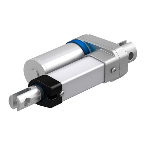
Ewellix CAMT20 User manual

CATEGORY
MAX 2 LINESINSTALLATION, OPERATION AND MAINTENANCE MANUAL
CAMT20
Linear actuator


33
Contents
1.0 General information......................................................4
1.1 Information in this manual ...............................................4
1.2 Explanation of symbols and signal words ......................4
1.3 Limitation of liability ........................................................5
1.4 Copyright.........................................................................5
1.5 Spare parts......................................................................5
1.6 Warranty terms................................................................5
1.7 Customer service ............................................................5
2.0 Safety .............................................................................6
2.1 Use ...................................................................................6
2.2 Responsibility of the owner and processor....................7
2.3 Personnel requirements..................................................7
2.4 Specic dangers .............................................................7
2.5 Safety equipment ............................................................8
2.6 Safeguard against restart ...............................................8
2.7 Modications of device ...................................................9
2.8 Manufacturer’s declaration of EMC compliance............9
3.0 Technical data............................................................. 15
3.1 Ambient conditions ....................................................... 15
3.2 Product label................................................................. 15
4.0 Structure and function...............................................16
4.1 O ver view ........................................................................ 16
4.2 Brief description............................................................ 16
4.3 Structure and function .................................................. 16
4.4 Attachment options....................................................... 19
4.5 Requirements for third party control units
(mandatory in medical applications)....................................23
4.6 Connections ..................................................................23
4.7 Operating elements....................................................... 24
4.8 Standard and Optional features ................................... 24
5.0 Transport, packaging and storage ...........................26
5.1 Safety information for transportation............................26
5.2 Transport inspection.....................................................26
5.3 Return to the manufacturer...........................................26
5.4 Packaging......................................................................26
5.5 Storage..........................................................................27
6.0 Installation and rst operation .................................28
6.1 Safety............................................................................. 28
6.2 Installation location.......................................................28
6.3 Inspections prior to initial operation............................. 28
6.4 Installation .....................................................................29
6.5 Connection to the control Unit ..................................... 31
6.6 Connection to operating element .................................32
6.7 Connection to power supply.........................................32
6.8 Initial start-up ................................................................32
7.0 Operation .....................................................................33
7.1 Safety .............................................................................33
7.2 Turn on...........................................................................33
7.3 Turn o...........................................................................33
7.4 Action before use ..........................................................33
7.5 Actions during operation...............................................34
7.6 Emergency disengagement ..........................................34
8.0 Maintenance................................................................35
8.1 Maintenance plan ..........................................................36
8.2 Maintenance work.........................................................36
8.3 Measures following completed maintenance...............37
9.0 Malfunctions................................................................38
9.1 Malfunction table...........................................................39
9.2 Start of operation after malfunction repair ...................39
10.0 Dismantling................................................................40
10.1 Dismantling..................................................................40
10.2 Disposal.......................................................................40
11.0 Appendix .................................................................... 41
11.1 Technical data.............................................................. 41
11.2 Plans and diagrams..................................................... 41
11.3 Approved accessories.................................................42
11.4 Plans and Diagrams ....................................................42
11.5 Ordering key ................................................................44
WARNING
Read this manual before installing, operating or maintaining this
actuator. Failure to follow safety precautions and instructions
could cause actuator failure and result in serious injury, death or
property damage. Keep this manual nearby for future reference.

4
CAMT20
1.0 General information
1.1 Information in this
manual
This manual provides important information on how to work
with the actuator (also called the device) safely and e-
ciently. The Manual is part of the device, must always be
kept and should be available for personnel to read at any
time. All personnel working with the device must read and
understand this manual before starting any work. Strict
compliance with all specied safety notes and instructions is
a basic requirement for safety at work.
Moreover, the accident prevention guidelines and general
safety regulations applicable at the place of use of the de-
vice must also be complied with.
For better representation of circumstances, the illustrations
in this manual are not necessarily to scale and may vary
from the actual design of the device.
All information and notes in this manual were compiled with
due consideration given to applicable standards and regula-
tions, the present status of technology and our years of
knowledge and experience.
1.2 Explanation of symbols
and signal words
Safety precautions are identied by symbols and signal
words dened on the right hand side of this page. These sig-
nal words indicate the severity of the hazard.
Adhere to these safety precautions and take caution in order
to avoid accidents that may result in personal injuries or
damage to property.
DANGER
Indicates a dangerous situation, which
will lead to death or serious personal
injury, if the precautionary measures are
ignored.
WARNING
Indicates a dangerous situation, which
can lead to minor or moderate injury or
property damage, if the precautionary
measures are ignored.
CAUTION
Indicates a dangerous situation, which
can lead to minor or moderate injury
the precautionary measures are ignored.
NOTICE
Indicates information considered
important, but not hazard-related (e.g.
messages relating to property damage).
NOTE
Emphasizes useful hints and
recommendations as well as information
for ecient and trouble-free operation.

5
1.0 General information
1.3 Limitation of liability
All information and notes in this manual were compiled un-
der due consideration of valid standards and regulations, the
present status of technology and our years of knowledge
and experience.
The manufacturer will not be liable for damage resulting
from:
• disregarding this manual
• unintended use
• employment of untrained personnel
• unauthorized conversions
• unauthorized technical modications
• manipulation or removal of the screws on the device
Where the device has been customized, the actual product
delivered maybe dierent from what is described in this
manual. In this case, ask Ewellix for any additional instruc-
tions or safety precautions relevant to these actuators.
We reserve the right to make technical modications in order
to impove usability.
1.4 Copyright
This manual is protected by copyright law and to be used
exclusively by Ewellix customers internal purpose
Passing this manual on to third parties, duplication of any
kind – even in the form of excerpts – as well as the use and/
or disclosure of the contents without the written consent of
the manufacturer is not permitted, except for internal
purposes.
Violation of Ewellix’s copyright may become the subject of a
future claim for damages.
1.5 Spare parts
This actuator is not designed for repair work. All warranty
and service claims become void without notice if any screws
on the linear actuator have been manipulated.
WARNING
Safety hazard caused by wrong parts
Wrong or faulty spare parts can adversely aect safety and
cause damage, malfunctions or total failure.
Therefore:
Use only genuine spae parts from the manufacturer
Spare parts in/on the device may only be replaced by the
manufacturer.
If the device cannot be repaired on site by authorized
personnel it must be dismantled and sent to the
manufacturer.
1.6 Warranty terms
The applicable and eective warranty terms are those con-
tained in the manufacturer’s terms and conditions of sale
contained in the Ewellix sales contract that governs this
sale.
1.7 Customer service
Ewellix Customer Service is always available to provide
technical information and answer questions.
The contact information for Ewellix Customer Service can be
found on www.ewellix.com

6
CAMT20
6
2.0 Safety
This section provides an overview of important safety as-
pects of installing, operating and maintaining this device.
Disregarding this Manual and safety regulations specied
therein may result in considerable danger and possible seri-
ous injury or death or damage to device or equipment.
2.1 Use
2.1.1 Intended use
The device has been designed and built exclusively for its
intended purpose as described in these instructions. The
device is to be used only for dynamic centric compression
and tensile-loaded lift of a load.
It is intended for interior use only. The device has been de-
signed for the movement of medical equipment, specically
medical procedure chairs, surgery and imaging tables.
However, the device is not designed for uncovered systems.
To avoid patient and operator to be injured, the device must
always be covered, so that the patient or operator could not
access the device.
WARNING
Risk from misuse
Any utilization of this device beyond its intended purpose may
lead to potential hazardous situations.
Therefore:
• Strictly adhere to all safety precautions and instructions in this
operating manual.
• Do not make this device suject to weather conditions, strong UV
rays, corrosive or explosive air media as well as other aggressive
media.
• Do not modify, retool or change the structural design or individual
components of the actuator.
• Never use the device outside of the technical application and op-
erational limits.
Range of environmental conditions:
• ambient temperature: 10 °C to + 40 °C
• relative humidity : 5% to 85%
• atmospheric pressure: 700 hPa to 1 060 hPa
2.1.1.1 Product lifetime
The linear actuator CAMT is designed for a service life of 10
years in a typical medical procedure equipment application.
Product service life of the linear actuator CAMT depends on
the stroke and load of the application. According to the L10
lifetime of the device, 60‘000 cycles can be achieved in an
average medical procedure application (average load of 3
000 N and average stroke of 100 mm).
2.1.2 Unintended Use
Any use other than the intended use, or modications to the
device without the manufacturer’s written agreement, or op-
eration beyond the technical limits, is considered
unauthorized.
Specic application exemptions are:
• Flammable anaesthetic mixture with air
• Flammable anaesthetic mixture with oxygen or nitrous oxide
• Increased radiation
• Places exposed to water (wet rooms).
NOTE
Any unauthorized use of the device can cause personal injury
and property damage. Always adhere to the instructions given in
this manual.
2.1.3 Essential performance
The essential performance of the linear actuator CAMT is to
move or hold a load within the boundaries dened by the de-
vice specications given in this operating manual and the
datasheet.
Any injury, damage or loss caused by violation of these in-
structions will be the responsibility of the customer.

7
2.0 Safety
7
2.2 Responsibility of the
owner and processor
The device is designed for commercial applications by its
owner or processor. The processor is the contracting part-
ner of the reseller or the manufacturer. The processor installs
the device in a complete system (application).
The owner or processor of the system is therefore subject to
the requirements of the Occupational Health and Safety Act.
In addition to the safety instructions in this manual, the
owner or processor must do the following concerning these
safety and accident prevention guidelines and environmental
protection regulations applicable to the site of the system’s
installation:
• Inform themselves of applicable industrial safety regula-
tions. They must also determine additional hazards that
arise due to the specic working conditions prevailing at
the site where the device is installed using risk assess-
ment. The risk assessment must be implemented in the
form of work instructions for device operation.
• Conrm that the work instructions created for the system,
including the device satisfy current legal requirements and
must alter the instructions accordingly.
• Clearly regulate and specify the responsibilities for installa-
tion, operation, maintenance, and cleaning.
• Ensure that all employees who deal with the device have
read and understood this manual.
• Provide personnel with the required protective equipment.
• Provide training for personnel at regular intervals and in-
form personnel of the hazards.
In addition, the owner or processors must ensure that the
device is in adequate working condition. They must do the
following:
• Ensure that the maintenance intervals described in these
instructions are complied with.
• Have all safety devices inspected regularly for function and
completeness.
2.3 Personnel
requirements
WARNING
Improper installation, operation and maintenance can result
in serious injury, death or property damage.
Use only qualied, instructed, or trained personnel (as described
below) who have read, understand and follow these instructions.
2.3.1 Qualications
The following qualications are specied for dierent areas
of activity listed in this manual:
• An instructed person (operator)
Instructed by the customer in an orientation session on the
assigned tasks and possible dangers arising from in case
of improper behaviour.
• Qualied personnel
Based on their professional training, know-how and expe-
rience as well as knowledge of the applicable standards
and regulations are able to independently perform as-
signed work activities and to detect and avoid possible
dangers
• Professional electrician
Based on his/her professional training, know-how and ex-
perience as well as knowledge of the applicable standards
and regulations is able to independently perform work on
electrical systems and to detect and avoid possible dan-
gers.
In addition, the professional electrician has been trained
for the special location where he/she works and knows the
relevant standards and regulations.
Only persons who can be expected to perform their tasks
reliably are permitted as personnel. Persons whose reaction
capabilities are impaired, e.g. through the use of drugs, al-
cohol or medication for example , are not permitted.
2.4 Specic dangers
The following section lists the residual risks that have been
determined by a risk assessment.
Heed the safety instructions listed here, and the warnings in
sub- sequent chapters of this manual, to reduce health haz-
ards and to avoid dangerous situations.
WARNING
Crush hazard
Do not let any object or person come in contact with the
lead screw and/or protection tube and/or the front and rear
attachment. Risk of damage to the linear actuator caused by
static and dynamic overloading of the actuator. Do not use the
actuator beyond the permissible operaring data.
WARNING
Pinch hazard
When the actuator runs into xed objects, the driving force can
cause personal injury. If the actuator is left unattended, check
that the full stroke length is free of obstacles and that there is
nobody in the stroke area. Alternatively, provide a means of
disconnetting all conductors from the mains power supply.

8
CAMT20
WARNING
Injury due to cracks and related openings in the housing of
the actuator and/or its accessories.
If the housing is damaged due to stock, beakage or heavy wear,
cease using the device and follow the dismantling instructions.
WARNING
Any side-acting forces can destroy the actuator and pose a risk
of serious injury. During the stroke, do not manipulate any of the
elements connected to the actuator.
WARNING
Danger of injury caused by moving components
Rotating and/or linearly moving components can cause serious
injuries.
Therefore:
• Do not work on, or place, hand, arms or any other parts of the
body, close to moving components.
2.5 Safety equipment
Integration of an emergency-stop system (for
certain applications)
The device is intended only for installation into an application or
system. It does not have its own operating control elements,
and does not have an independent emergency-stop function.
Therefore, the device must be installed so that it is part of an
emergency shuto system and can be stopped if necessary.
The emergency shut-o system must be connected in such
a way that any disruption of the power supply or reactivation
of the power supply after a power disruption, cannot cause a
hazardous situation for persons or objects.
The emergency shut-o system must always be freely
accessible.
NOTE
The processor decides which applications require installation of
an emergency shut-o system.
Integration of a patient release system (for
certain applications)
The device is intended only for installation into an applica-
tion or system. It does not have its own operating control el-
ements, and does not have an independent patient release
mechanism. In the event of a malfunction, the device cannot
extend or retract.
If required by the application, a separate provision for pa-
tient release must be installed, to allow safe release of the
patient in case of emergency, or equipment failure.
NOTE
The processor decides whether the intended application requires
the installation of an emergency patient release system.
Integration of a safety mechanism to prevent
unintended triggering of the operating device
(for certain applications)
The device does not have its own operating control elements
and does not have a safety mechanism against unintended
triggering of the operating device.
If required by the application, a safety provision must be
provided to prevent unintended triggering of the operating
device.
NOTE
The processor decides whether the intended application requires
the installation of an safety mechnism to prevent unintended
triggering of the operating device.
The following safety mechanisms have been
installed:
• Backup nuts are tted on the leadscrew to prevent the lin-
ear actuator From collapsing if there is a gear nut failure.
• End limit switches are installed to provide a safe current
cut-o when the end of stroke position of the device is
reached. In case of failure of the end limit switches, a me-
chanical safety end-stop prevents the device from exceed-
ing its intended stroke.
2.6 Safeguard against
restart
WARNING
Life-threatening situation through unauthorized restart!
For work in hazard zones, there is a risk that the power
supplycould be turned on without prior authorization. This
presents a potentially life-threatening situation for people in the
hazard zone.
Therefore:
• Read the information contained in this manual, concerning safe-
guarding against any unintentional restart of the power supply.
• Always follow the procedure as described below.
Protect CAMT against an unauthorized restart
Disconnect the power line plug out of the control unit and /
or the linear actuator.

9
2.0 Safety
9
2.7 Modications of
device
WARNING
To avoid hazardous situations and to ensure optimal
performance, do not make changes or modications to the
device unless they have been specically authorized by Ewellix.
2.7.1 Warning labels
The following symbols and information decals can be found
in the danger zone. They refer to the immediate vicinity
around their location.
WARNING
Danger of injurt because of illegible symbols
Over the course of time stickers and decals may bcome dirty or
illegible for some other reason.
Therefore:
• Keep any safety, warning and operation related decals in
legible condition at all time
• Replace damaged decals or stickers immediately
2.8 Manufacturer’s
declaration of EMC
compliance
EN 60601-1-2:2015 (IEC 60601-1-2:2014) Medical Electrical
Equipment -
Part 1-2: General requirements for basic safety and essential
performance –
Collateral Standard: Electromagnetic disturbances –
Requirements and tests
2.8.1 Instructions for use
General
Professional healthcare facility environment
Physician oces, dental oces, clinics, limited care facili-
ties, freestanding surgical centers, freestanding birthing
centers, multiple treatment facilities, hospitals (emergency
rooms, PATIENT rooms, intensive care, surgery rooms, ex-
cept near HF SURGICAL EQUIPMENT, an MR system out-
side a RF shielded room of an ME SYSTEM for magnetic
resonance imaging).
Essential performance
The essential performance about the linear actuator CAMT
is to keep, hold and move weights, loads.
The risk management (Document L5672,0048) identify the
functions about safety of these linear actuators. All features
or functions are performed properly. Unacceptable risks for
patients, operators or others are performed and assessed to
prevent or reduce harm.
The follow points identify and describe the EMC-risks about
the Telescopic pillar CAMT according the EMC-measurements:
Warning against the stacking of equipment
WARNING
Stacked with other equipment
Use of this equipment adjacent to or stacked with other
equipment should be avoided because it could result in improper
operation. If such use is necessary, this equipment and the other
equipment should be observed to verify that they are operationg
normally
List of cables, length of cables, accessories
WARNING
Use of accessories, transducers and cable
The use of accessories, transducers and cable other then those
spacied or provided by the manufacturer of this equipment
could result in increased electromagnetic emissions or
decreased electromagnetic immunity of this equipment and
result in
improper operation.

10
CAMT20
10
Connection cable (CAMT <-> Control unit SCU;
SCU <-> Operating elements)
Description Plug Drawing-No Type Length
m
Connecting cable straight:
CAMT – SCU DIN 8p – Molex 6p 777400-1000 2 x AWG16 &
4 x AWG24 1
Connecting cable straight:
CAMT – SCU
DIN 8p – Molex 6p
DIN 8p – open wire 777400-2300 2 x AWG16 &
4 x AWG24 2.3
Connecting cable coiled:
SCU – Hand switch HD 15p 160600-1350 15 x AWG30 1.3/2.3
Connecting cable straight:
SCU – Foot switch HD 15p 160632-2500 10 x AWG28 2.5
Connecting cable coiled:
SCU – Foot switch HD 15p 160633-2500 10 x AWG28 1.2/2.5
Connecting cable straight:
SCU – Desk switch HD 15p 160634-2500 10 x AWG28 2.5
Power cables (Main <-> Control unit SCU)
Description Plug Country Drawing-No Length Comment
m
Straight power cable Schuko Euro ZKA-160637-3500 3.5
Straight power cable SEV CH ZKA-160638-3500 3.5
Straight power cable UL/CSA (NEMA 5-15p) USA/CAN ZKA-160639-3500 3.5 SJT-cable
Straight power cable UL/Hospital grade
(NEMA 5-15p) USA/CAN ZKA-160640-3500 3.5 SJT-cable
Straight power cable British plug UK ZKA-160609-3500 3.5
RF Communication Equipment
WARNING
Portable RF communications equipment
Portable RF communications equipment (including peripherals
such as antenna cables and external antennas) should be used
no closer than 30 cm (12 inch) to any part of CAMT, including
cable spacied by the manufacturer. Otherwise, degradation of
the performance of this equipment could result.
2.8.2 Technical description
Requirements applicable to all ME equipment
and ME systems
This chapter describes precautions to be taken to prevent
adverse events to the patent and operator due to electro-
magnetic disturbances.

11
2.0 Safety
11
2.8.2.1 Compliance for each Emissions and
Immunity standards
The Telescopic pillar CAMT (CAMT & SCU) is intended for
use in the electromagnetic environment specied. It com-
plies with the standard for emission class and group and im-
munity test level as follows.
a) CAMT stand-alone
CISPR 14-1
The CAMT is intended for use in the electromagnetic environment specied below. The customer or the user of the CAMT should assure
that it is used in such an environment.
Emissions test Compliance Electromagnetic environment - guidance
RF emissions
CISPR 14-1
Complies The CAMT is not suitable for interconnection with other equipment.
Harmonic emissions
IEC 61000-3-2
Not applicable The CAMT is suitable for use in all establishments, including domestic
establishments and those directly connected to the public low-voltage
power supply network that supplies buildings used for domestic
purposes.
Voltage uctuations /
icker emissions
IEC 61000-3-3
Not applicable
Electromagnetic immunity environment tested
The CAMT is intended for use in the electromagnetic environment specied below. The customer or the user of the CAMT should assure
that it is used in such an environment.
Immunity test IEC 60601 test level Compliance level Electromagnetic environment
- guidance
Electrostatic
discharge (ESD)
IEC 61000-4-2
± 8 kV contact
± 2, ± 4, ± 8, ± 15 kV air
± 8 kV contact
± 2, ± 4, ± 8, ± 15 kV air
Floors should be wood, concrete or ceramic
tile. If oors are covered with synthetic
material, the relative humidity should be at
least 30%.
Electrical fast
transient/burst
IEC 610004-4
± 2 kV, 5 and 100 kHz
for power supply lines*
± 1 kV, 100 kHz
for input/output lines*
Mains power quality should be that of
typical commercial or hospital environment.
*Not applicable for DC and I/O if cable
< 3 m
Surge
IEC 61000-4-5
±0.5, ±1 kV
line(s) to line(s)*
±0.5, ±1, ± 2 kV
line(s) to earth*
Not applicable Mains power quality should be that of
typical commercial or hospital environment.
*Not applicable for DC and I/O if cable
< 3 m
Voltage dips, short
interruptions and voltage
variations on power supply
input lines
IEC 61000-4-11
0% UT: 0.5 cycle
At 0°, 45°, 90°, 135°, 180°, 225°, 270°
and 315°
0% UT: 1 cycle
At 0°
0% UT: 250/300 cycles
At 0°
70% UT: 25/30 cycles
At 0°"
Not applicable Mains power quality should be that of
typical commercial or hospital environment.
*Not applicable for DC and I/O if
cable < 3 m
If the user of the CAMT requires continued
operation during power mains interruptions,
it is recommended that the CAMT be
powered from an uninterruptible power
supply or battery.
UT is the a.c. mains voltage (24 VDC) prior
to application of the test level.
Power frequency
(50/60 Hz)
magnetic eld
IEC 61000-4-8
30 A/m
50/60 Hz
30 A/m
50/60 Hz
Power frequency magnetic elds should be
at levels characteristic of a typical location
in a typical commercial or hospital
environment.

12
CAMT20
12
b) CAMT and SCU
CISPR 14-1
The CAMT is intended for use in the electromagnetic environment specied below. The customer or the user of the CAMT should assure
that it is used in such an environment.
Emissions test Compliance Electromagnetic environment - guidance
RF emissions
CISPR 14-1
Complies The CAMT is not suitable for interconnection with other
equipment.
Harmonic emissions
IEC 61000-3-2"
Class A The CAMT is suitable for use in all establishments,
including domestic establishments and those directly
connected to the public low-voltage power supply
network that supplies buildings used for domestic
purposes.
Voltage uctuations /
icker emissions
IEC 61000-3-3
Complies
Electromagnetic immunity environment tested
The CAMT is intended for use in the electromagnetic environment specied below. The customer or the user of the CAMT should assure
that it is used in such an environment.
Immunity test IEC 60601 test level Compliance level Electromagnetic
environment - guidance
Electrostatic
discharge (ESD)
IEC 61000-4-2
± 8 kV contact
± 2, ± 4, ± 8, ± 15 kV air
± 8 kV contact
± 2, ± 4, ± 8, ± 15 kV
air
Floors should be wood, concrete or
ceramic tile. If oors are covered with
synthetic material, the relative
humidity should be at least 30%.
Electrical fast
transient/burst
IEC 610004-4
± 2 kV, 100 kHz
for power supply lines*
± 1 kV, 100 kHz
for input/output lines*
±2 kV, 5 and 100 kHz
for power supply lines*
±1 kV, 100 kHz
for input/output lines*
Mains power quality should be that of
typical commercial or hospital
environment.
*Not applicable for DC and I/O if
cable < 3 m
Surge
IEC 61000-4-5
±0.5, ±1 kV
line(s) to line(s)*
±0.5, ±1, ± 2 kV
line(s) to earth*
±0.5, ±1 kV
line(s) to line(s)*
±0.5, ±1, ± 2 kV
line(s) to earth*
Mains power quality should be that of
typical commercial or hospital
environment.
*Not applicable for DC and I/O if
cable < 3 m
Voltage dips, short
interruptions and voltage
variations on power supply
input lines
IEC 61000-4-11
0% UT: 0.5 cycle
At 0°, 45°, 90°, 135°, 180°, 225°, 270° and 315°
0% UT: 1 cycle
At 0°
0% UT: 250/300 cycles
At 0°
70% UT: 25/30 cycles
At 0°"
0% UT: 0.5 cycle
At 0°, 45°, 90°, 135°,
180°, 225°, 270° and
315°
0% UT: 1 cycle
At 0°
0% UT: 250/300 cycles
At 0°
70% UT: 25/30 cycles
At 0°
Mains power quality should be that of
typical commercial or hospital
environment.
*Not applicable for DC and I/O if
cable < 3 m
If the user of the CAMT requires
continued operation during power
mains interruptions, it is
recommended that the CAMT be
powered from an uninterruptible
power supply or battery.
UT is the a.c. mains voltage (24 VDC)
prior to application of the test level.
Power frequency
(50/60 Hz)
magnetic eld
IEC 61000-4-8
30 A/m
50/60 Hz
30 A/m
50/60 Hz
Power frequency magnetic elds
should be at levels characteristic of a
typical location in a typical
commercial or hospital environment.

13
2.0 Safety
13
c) CAMT stand-alone / CAMT and SCU
Electromagnetic immunity environment tested
Portable and mobile RF communications equipment should be used no closer to any part of the CAMT, including cables, than the
recommended separation distance calculated from the equation applicable to the frequency of the transmitter.
These guidelines may not apply in all situations. Electromagnetic propagation is aected by absorption and reection from structures,
objects and people. Field strengths from xed transmitters, such as base stations for radio (cellular/cordless) telephones and land mobile
radios, amateur radio, AM and FM radio broadcast and TV broadcast cannot be predicted theoretically with accuracy. To assess the
electromagnetic environment due to xed RF transmitters, an electromagnetic site survey should be considered.
Immunity test IEC 60601 test level Compliance level Electromagnetic
environment - guidance
Conducted RF
IEC 61000-4-6
3 Vrms
150 kHz to 80 MHz outside ISM bands and
radio amateur band *
10 Vrms
150 kHz to 80 MHz
outside ISM bands and
radio amateur band *
If the measured eld strength in the
location in which the CAMT is used
exceeds the applicable RF compliance
level, the CAMT should be observed
to verify normal operation. If abnormal
performance is observed, additional
measures may be necessary, such as
reorienting or relocating the CAMT.
6 Vrms
150 kHz to 80 MHz in ISM bands and radio
amateur band *
10 Vrms
150 kHz to 80 MHz in
ISM bands and radio
amateur band *
Radiated RF
IEC 61000-4-3
10 V/m
80 MHz to 2.7 GHz
80% AM at 1 kHz
10 V/m
80 MHz to 2.7 GHz
80% AM at 1 kHz
Minimum separation distance shall be
calculated by following equation:
E = P
6
d
E is the immunity test level in [V/m]
d is the minimum separation in [m]
P is the maximum power in [W]
Proximity eld from RF
wireless communication
equipment
IEC 61000-4-3
27 V/m
380-390 MHz
50 % PM 18 Hz
28 V/m
430-470 MHz
FM ±5 kHz deviation,
1kHz sine
9 V/m
704-787 MHz
50 % PM 217 Hz
28 V/m
800-960 MHz
50 % PM 18 Hz
28 V/m
1700-199 0 MHz
50% PM 217 Hz
28 V/m
2400-2570 MHz
50% PM 217 Hz
9 V/m
5100-5800 MHz
50% PM 217 Hz
27 V/m
380-390 MHz
50 % PM 18 Hz
28 V/m
430-470 MHz
FM ±5 kHz deviation,
1kHz sine
9 V/m
704-787 MHz
50 % PM 217 Hz
28 V/m
800-960 MHz
50 % PM 18 Hz
28 V/m
1700-199 0 MHz
50% PM 217 Hz
28 V/m
2400-2570 MHz
50% PM 217 Hz
9 V/m
5100-5800 MHz
50% PM 217 Hz
RF wireles equipement maximum
output power and separation distance
tested (at 30 cm) :
TETRA 400: max 1.8 W
GMRS 460, FRS 460: max 2 W
LTE Band 13 and 17; max 0.2 W
GSM 800/900: max 2 W
TETRA 800: max 2 W
iDEN 820: max 2 W
CDMA 850: max 2 W
LTE Band 5: max 2 W
GSM 1800/1900: max 2 W
CDMA 1900: max 2 W
DECT: max 2 W
LTE Band 1, 3, 4 and 25: max 2 W
UMTS: max 2 W
Bluethooth: max 2 W
WLAN 802.11b/g/n: max 2 W
RFID 2450: max 2 W
LTE Band 7: max 2 W
WLAN 802.11 a/n: max 0.2 W
Interference may occur in the vicinity
of equipment marked with the
following symbol:
*The ISM (industrial, scientic and medical) bands between 150 kHz and 80 MHz are 6.765 - 6.795 MHz, 13.553 - 13.567 MHz, 26.957 - 27.283 MHz and 40.66 - 40.7 MHz. The amateur
radio bands between 0.15 MHz and 80 MHz are 1.8 MHz - 2 MHz, 3.5 - 4.0 MHz, 5.3 - 5.4 MHz, 7 - 7.3 MHz, 10.1 - 10.15 MHz, 14 - 14.2 MHz, 18.07 - 18.17 MHz, 21.0 - 21.4 MHz, 24.89 -
24.99 MHz, 28.0 - 29.7 MHz and 50.0 - 54.0 MHz.
If the measured eld strength in the location in which the CAMT is used exceeds the applicable RF compliance level above, the CAMT should be observed to verify normal operation. If
abnormal performance is observed, additional measures may be necessary, such as reorienting or relocating the CAMT.

14
CAMT20
14
Recommended separation distances between portable and mobile RF communications equipment and the CAMT
The CAMT is intended for use in the electromagnetic environment in which radiated RF disturbances are controlled. The customer or the
user of the CAMT can help prevent electromagnetic
The CAMT is intended for use in the electromagnetic environment in which radiated RF disturbances are controlled. The customer or the
user of the CAMT can help prevent electromagnetic interference by maintaining a miminum distance between portable and mobile RF
communications equipment (transmitters) and the CAMT as recommended below, according to the maximum output power of the
communication equipment.
Rated maximum
output power of
transmitter [W]
Separation distance according to frequency of transmitter [m]
150 kHz to 80 MHz outside ISM
and radio amateur bands *
150 kHz to 80 MHz
in ISM and radio
amateur bands *
80 MHz to 2700 MHz
(for dene RF Wireless transmitters
see table before)
d = 0,35√P **
0,01 0,04 0,12 0,06
0,1 0,13 0,38 0,19
10,40 1,2 0,60
10 1,3 3,8 1,9
100 4,0 12 6,0
For transmitters rated at a maximum output power not listed above, the recommended separation distance d in metres [m] can be
determined using the equation applicable to the frequency of the transmitter, where P is the maximum output power rating of the
transmitter in watts [W] according to the transmitter manufacturer.
E = P
6
d
*The ISM (industrial, scientic and medical) bands between 150 kHz and 80 MHz are 6.765 - 6.795 MHz, 13.553 - 13.567 MHz, 26.957 - 27.283 MHz and 40.66 - 40.7 MHz. The amateur
radio bands between 0.15 MHz and 80 MHz are 1.8 MHz - 2 MHz, 3.5 - 4.0 MHz, 5.3 - 5.4 MHz, 7 - 7.3 MHz, 10.1 - 10.15 MHz, 14 - 14.2 MHz, 18.07 - 18.17 MHz, 21.0 - 21.4 MHz, 24.89 -
24.99 MHz, 28.0 - 29.7 MHz and 50.0 - 54.0 MHz.
**Formulas coming from Ed.3 of the IEC 60601-1-2
2.8.2.2 Results and Deviations from
Standards and allowances used
Info about results, deviations see chapter 2.8.2.1. There are
no other deviation from the collateral standard.
2.8.2.3 Maintaining BASIC Safety and
Essential performance
Its mandatory to maintain the Linear actuator (and the con-
trol unit SCU) To save the essential performance for the ex-
pected Service life.
One time approved in the nal application not change is al-
lowed due to the EMC inuence.
NOTE
Do not change the once installed nal application due to EMC
view.
WARNING
This product was tested against actual conditions of frequency
wireless environment present in Europe.

15
3.0 Technical data
15
3.1 Ambient conditions
• Indoor use only
• Ambient temperature +10 to +40 °C
• Atmospheric humidity from 5% to 85%
• Air pressure from 700 to 1 060 hPa
3.2 Product label
Type label (without options)
1. Type designation
2. Manufacturer
3. Maximum current consumption
4. Duty cycle of operation (ON/OFF time)
5. Nominal Speed
6. Serial number
7. Indoor use only
8. CE mark
3.0 Technical data
9. UL certication mark
10. Recommendation to read operating manual
11. Disposal information
12. Date of manufacture (month, year)
13. Maximum stroke
14. Manufacturer’s address
15. Nominal force
16. Voltage
Location of the
product label
1 2 4 5 6
789101112131415
3
16

16
CAMT20
4.3 Structure and
function
Connection port
The connection port uses a 6-pole Molex Mini-t Jr. connec-
tor. It is used to interface the CAMT with the control unit by
the mean of an optional detachable motor cable that can be
supplied in dierent lengths (⮑ g. 1). For detailed control
and connection details please refer to chapter 4.5
Requirements for third party control units (mandatory in
medical applications) (⮑ page 23) and chapter 4.6
Connections (⮑ page 23).
Fig. 1
Motor
The motor is a 24V brush DC motor. Its speed depends on
the magnitude and the direction of the load as well as the di-
rection of the movement. The motor has a 2-Hall Encoder
impulse transmitter with a 2 poles magnet built-in. For de-
tailed control and connection details please refer to chapter
4.0 Structure and function
4.1 Overview
1. Adjustable front and rear end stop
2. Connection port (Molex Mini-Fit Jr. 6 Pole)
3. Gearbox
4. Limit switches with cover
5. DC Motor
6. Protection tube
7. Lead screw
8. Front attachment
9. Rear attachment
4.2 Brief description
The CAMT linear actuator is implemented in an application
and is exclusively for the centric tensile- and compres-
sive-loaded lift. The actuator requires an external control unit
to power the motor. The control unit is connected to the ac-
tuator via a detachable connection cable. The Ewellix oper-
ating control element is also connected to the control unit.
The actuator consists of a gearbox that is common to all the
versions. Several front and rear attachment options are
available (refer to chapter ⮑ 4.4 Attachment Options,
page 19).
The gearbox is composed with a direct current motor that
drives a trapezoidal sliding screw via a worm gear.
The leadscrew itself is self-locking to prevent the actuator
from driving back, without an additional brake.
1
1
7
89
23
4
6
5

17
4.0 Structure and function
4.5 Requirements for third party control units (manda-
tory in medical applications) (⮑ page 23) and chapter 4.6
Connections (⮑ page 23).
Gearbox
The gearbox contains the drive system that converts the
motor’s rotary motion into the translation motion of the
spindle.
This is done through the use of a worm gear and a lead-
screw. The worm shaft is directly integrated to the motor
and the worm wheel is integrated to the trapezoidal lead
screw nut.
A backup nut is located on the leadscrew to prevent the col-
lapse of the actuator in case of a failure of the screw nut.
The gearbox is pre-loaded to eliminate the axial clearance.
Protection tube
The main function of the protection tube is to provide an in-
terface for the rear attachment.
The length and the machining of the protection tube there-
fore vary depending on the selected attachment options.
The protection tube can be delivered as “short” or “long”.
When “short” (⮑ g. 2), the protection tube is just long
enough to provide the space necessary for the attachment
regardless of the stroke. This option leaves the spindle un-
covered for all strokes from 100 mm and above.
Fig. 2
When “long” (⮑ g. 3), the protection tube covers the entire
spindle. Even so, the rear side of the tube remains open to
leave access to the adjustable end-stop.
Fig. 3
WARNING
Safety hazard caused by interference
When using a short protction tube in combination with a long
leadscrew, the kinematic of the system should be carefully
studied to not get any interference between the back of the
spindle and the supporting pillar (or supporting structure in
general).
In worst case the interference could lead to a break or collapse
of the actuator and/or the support structure.
End position
The actuator stroke is limited by integrated end limit
switches that cut the power to the DC motor.
The end-stops are used to activate the limit switches via the
two at springs that are attached on both sides of the main
housing and front cover. When the end-stops contact the at
springs, the latter deect and activate the limit switches that
are located on a PCB above the gearbox.

18
CAMT20
The upper and the lower end position may be adjusted by
changing the position of the end stops using standard tools:
• 22 mm at wrench for the front end-stop
• 22 mm tube spanner for the rear end-stop
In case of a system malfunction, when the spindle moves
beyond the end limit switches, the end-stops act as me-
chanical safety end-stops and halt the movement.
When an end-stop hits a xed surface on the housing or
cover, the external control unit detects the peak of current
that results of this and consequently cuts it o, preventing
the motor from overheating.
WARNING
Safety hazard caused by loosen and stop
The end stops are designed to be adjusted several times.
However, after every adjustment it must be checked that the
torque is still high enough to hold the position.
Minimum torque must be 0,5 Nm.
In case the torque is too low, there is a risk that the end stop
could unintentionally change the position or in the worst case the
rear end stop could drop from the leadsrew. this could lead to
collapse of the actuator.
External control unit
The DC motor is powered via an external control unit
through the connection port. The control unit controls the
running direction of the linear actuator. The 2 motor built-in
hall encoders signals can be accessed by the controller to
enable variable speed control or positioning.
The control unit is also used to provide a soft start/stop
function in order to avoid shocks that could negatively aect
the user experience of the device on which the CAMT is
mounted.
Ultimately, in case of overload, the control limits the current
in order to prevent the motor from overheating and damag-
ing the actuator.
Ewellix advises to use one of the following control units to-
gether with the CAMT actuator:
Control units
SCU 1
SCU 5
SCU 9
VCU 5
VCU 8
VCU 9
*BCU 5
*BCU 8
CAMT
NOTE
In case of use of a third-party control unit, refer to chapter
5.4 Requirements for third party control units (mandatory
in medical applications) (⮑ page 24) and chapter 4.6
Connections (⮑page 25).

19
4.0 Structure and function
4.4 Attachment options
Several types of attachments provide exibility to install the
CAMT on the supporting structure.
Most feature a set of matching front and rear interfaces:
• Ø8 bore on spindle (front), clevis attachment (rear)
(⮑ g. 4)
• clevis attachments (front and rear) (⮑ g. 5)
• brackets, 1-axis (1 degree-of-freedom, front and rear)
(⮑ g. 7)
• brackets, 2-axis (2 degree-of-freedom, front and rear)
(⮑ g. 8)
• U-bracket, 1-axis (1 degree-of-freedom, rear only)
(⮑ g. 6)
Clevis attachments are popular in the industry and are in
this case, available with high accuracy bores (H7) to keep
the play in the attachment reduced to the minimum.
The 1 and 2 degree-of freedom rear brackets are designed
to t directly on a Ewellix telescopic pillar (CPMT, TLG and
TLT) and respectively allow the 1 or 2-axis movements nec-
essary to the application.
Fig. 4
Fig. 5
Fig. 6
Fig. 7
Fig. 8
4.4.1 Spindle with 8H7 bore (front
attachment)
The simplest available standard front attachment is a Ø 8H7
(+0.015/0.000) bore in the lead screw (⮑ g. 9).
Fig. 9

20
CAMT20
NOTE
If the bore will be used as the pivot point, it is recommended to
use a DIN 6325 cylinder pin with Ø 8h7 (+0,000/-0,015) to have a
loose t.
In case the pin should be xed in the lead screw bore and
the pivot point is provided by a customer designed clevis, it
is recommended to use a DIN 6325 cylinder pin with Ø 8m6
(+0,015/+0,06) to have a transition t.
4.4.2 Clevis attachments
The clevis attachment set is composed of specic front and
rear interfaces.
The clevis front interface (⮑ g. 10) includes an additional
head that is put at the extremity of the spindle and that fea-
tures a Ø12H7 (+0,018/-0.000) bore. An elastic pin is cross
tted through the clevis head and spindle to ensure the
clevis head will not get lose over time.
Fig. 10
NOTE
If the bore will be used as the pivot point, it is recommended to
use a DIN 6325 cylinder pin with Ø 12h7 (+0,000/-0,018) to have
a loose t.
In case the pin should be xed in the bore and the pivot point is
provided by a customer designed clevis, it is recommended to
use a DIN 6325 cylinder pin with Ø 12m6 (+0,018/+0,007) to have
a transition t.
The rear interface (⮑ g. 11) is composed of 2 bushings
with Ø 20H7 (+0.021/0.000) that are tted to the protection
tube.
As standard, this bushings are located under the spindle so
that it is possible for a pin to totally cross the protection
tube. Optionally, these bushings can be located higher on
the tube, toward the gearbox. In this case, the mounting can
only be in a trunnion conguration.
It should be noted that in order to keep a low play congura-
tion, the clevis pins used both for the front and rear attach-
ments should be of matching dimension/tolerance.
Fig. 11
NOTE
It is recommended to use a DIN 6325 cylinder pin with Ø 20h7
(+0,000/-0.021) to have a loose t.
4.4.3 Degree-of-freedom (1-DOF)
brackets
The front bracket is attached to the CAMT spindle through a
Ø8 dowel pin and allows for a single axis movement only,
around this same pin (⮑ g. 12). The dowel pin is xed rela-
tively to the spindle and the bracket swivels around it, sup-
ported by 2 bushings.
The connection to the upper structure is done through 2
standard M10 screws.
Fig. 12
Table of contents
Other Ewellix Controllers manuals