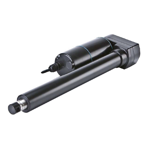
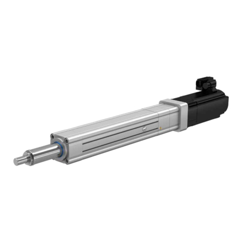
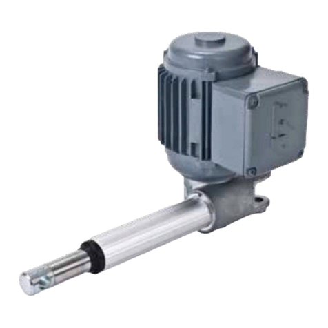
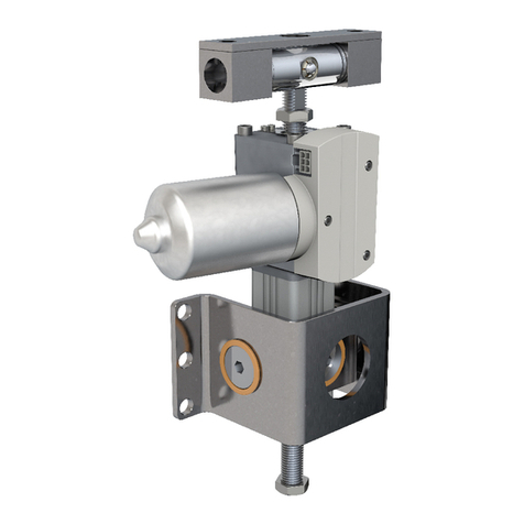
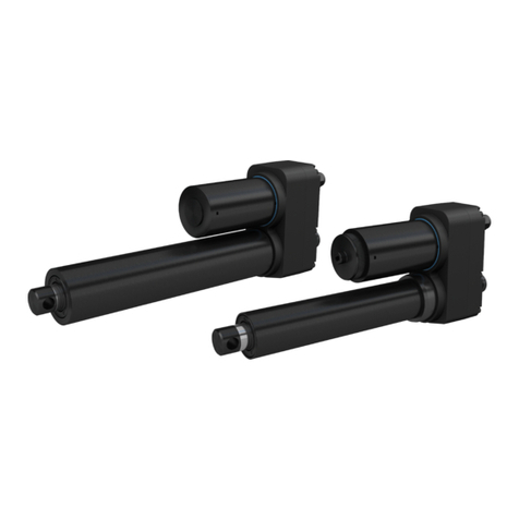
Ewellix CAHB-10 User manual

CATEGORY
MAX 2 LINESINSTALLATION, OPERATION AND MAINTENANCE MANUAL
CAHB-10


33
Contents
1.0 General information ...................................................4
1.1 Information on this manual ..........................................4
1.2 Explanation of symbols................................................4
1.3 Limitation of liability .....................................................5
1.4 Warranty terms.............................................................5
1.5 Customer service .........................................................5
2.0 Safety ...........................................................................6
2.1 Intended used...............................................................6
2.2 Responsibility of the owner and processor.................6
2.3 Personnel requirements...............................................6
2.3.1 Qualications ...........................................................7
2.4 Specicdangers ..........................................................7
2.5 Safety equipment .........................................................7
2.6 Changesandmodicationsontheactuator ...............8
3.0 Technical data.............................................................9
3.1 Operatingconditions....................................................9
3.2 Product label ................................................................9
4.0 Structure and function.............................................10
4.1 O ve r vi ew ..................................................................... 10
4.2 Brief description ......................................................... 10
4.3 Constructiongroupdescription................................. 11
4.4 Connections .............................................................. 11
4.5 Features...................................................................... 12
4.5.1 Limit switch ............................................................ 12
4.5.2 Potentiometer......................................................... 12
4.5.3 Thermal switch....................................................... 12
4.5.4 2-Hall encoder (optional) ....................................... 12
4.5.5 Absoluteanalogpositionoutput ........................... 12
5.0 Transport, packaging and storage.........................13
5.1 Safety information for the transport........................... 13
5.2 Transport inspection .................................................. 13
5.3 Return to the manufacturer ........................................ 13
5.4 Packaging................................................................... 13
5.5 Storage ....................................................................... 14
6.0 Installationandrstoperation ............................... 15
6.1 Installation location .................................................... 15
6.2 Installation .................................................................. 15
6.3 Inspectionspriortorstoperation............................. 16
6.4 Connect to power supply........................................... 16
7.0 Operation................................................................... 17
7.1 Safety.......................................................................... 17
7.2 Action before operation ............................................. 17
7.3 Actionduringoperation.............................................. 17
7.3.1 Normal operation ................................................... 17
7.4 Disengagementincaseofemergency ...................... 18
7.5 Action after use .......................................................... 18
8.0 Maintenance..............................................................19
8.1 Spare parts................................................................. 19
8.2 Maintenance plan....................................................... 19
8.3 Maintenance work......................................................20
8.3.1 Cleaning .................................................................20
8.3.2 Inspectionsandreadings ......................................20
8.3.3 Check of visual condition ......................................21
8.4 Measures after completed maintenance ...................21
9.0 Malfunctions .............................................................22
9.1 Malfunction table........................................................23
9.2 Startofoperationafterxingmalfunction.................23
10.0 Dismantling ...............................................................24
10.1 Dismantling................................................................. 24
10.1.1 DismantlingofCAHB-10 ........................................ 24
10.2 Disposal...................................................................... 24
11.0 Appendix....................................................................25
WARNING
Readthismanualbeforeinstalling,operatingormaintainingthis
actuator. Failure to follow safety precautions and instructions could
causeactuatorfailureandresultinseriousinjury,deathorproperty
damage.

4
CAHB-10 series
1.0 General information
1.1 Information on this
manual
This manual provides important information on how to work
withtheactuatorsafelyandeciently.
Themanualispartoftheactuator,mustalwaysbekeptin
the actuator’s direct proximity and should be available for
thepersonnelatanytime.Allpersonnelworkingwiththeac-
tuatormustreadandunderstandthismanualbeforestarting
anywork.Strictcompliancewithallspeciedsafetynotes
and instructions is a basic requirement for safety at work.
Moreover,theaccidentpreventionguidelinesandgeneral
safety precautions applicable at the place of use of the actu-
ator must also be complied with.
Forbetterrepresentationofcircumstances,theillustrations
used are not necessarily to scale and may vary from the ac-
tualdesignoftheactuator.
1.2 Explanation of
symbols and signal words
Safety precautions
Safetyprecautionsareidentiedbysymbolsandsignal
words.Thesesignalwordsindicatetheseverityofthe
hazard.
Adhere to these safety precautions and act cautiously in or-
dertoavoidaccidents,personalinjuriesanddamageto
property.
DANGER
Indicatesadangeroussituation,which
will lead to death or serious personal
injury,iftheprecautionarymeasuresare
ignored.
WARNING
Indicatesadangeroussituation,which
can lead to minor or moderate injury or
propertydamage,iftheprecautionary
measuresareignored.
CAUTION
Indicatesadangeroussituation,which
can lead to minor or moderate injury
theprecautionarymeasuresareignored.
NOTICE
Indicates information considered
important,butnothazard-related(e.g.
messagesrelatingtopropertydamage).
NOTE
Emphasizes useful hints and
recommendations as well as information
forecientandtrouble-freeoperation.

5
1.0 General information
1.3 Limitation of liability
All information and notes in this manual were compiled un-
derdueconsiderationofvalidstandardsandregulations,the
presentstatusoftechnologyandouryearsofknowledge
and experience.
Themanufacturerwillnotbeliablefordamageresulting
from:
• disregardingthismanual
• unintended use
• employment of untrained personnel
• unauthorized conversions
• technicalmodications
• manipulation or removal of the screws on the actuator
• use of unapproved spare parts
Incasetheactuatoriscustomised,theactualproductdeliv-
eredmaybedierentfromwhatisdescribedinthemanual.
Inthiscase,askEwellixforanyadditionalinstructionsor
safety precautions relevant to these actuators.
Wereservetherighttomaketechnicalmodicationstothe
actuator to improve usability.
1.4 Warranty terms
Theapplicableandeectivewarrantytermsarethosecon-
tained in the manufacturer’s terms and conditions of sale.
1.5 Customer service
Ewellix Customer Service is always available to provide tech-
nical information and answer questions.
The contact information for Ewellix Customer Service can be
found on www.ewellix.com.

6
CAHB-10 series
6
2.0 Safety
This chapter provides an overview of important safety pre-
cautions and information necessary for safe and trou-
ble-freeinstallation,operationandmaintenance.
DisregardingthisManualandsafetyprecautionsspecied
thereinmayresultinconsiderabledangerandpossibleseri-
ous injury or death.
2.1 Intended use
Theactuatorhasbeendesignedandbuiltexclusivelyforits
intended purpose as described in these instructions.
WARNING
Risk from misuse!
Any utilization of this actuator beyond its intended purpose may
lead to potentially hazardous situations.
Therefore,followtheprecautionsbelow:
• Strictly adhere to all safety precautions and instructions in this
manual.
• Donotallowthisactuatortobesubjectedtoweatherconditions,
strongUVrays,corrosiveorexplosiveairmediaaswellasother
aggressivemedia.
• Donotmodify,retoolorchangethestructuraldesignorindividual
components of the actuator.
• Never use the actuator outside of the technical application and
operational limits.
2.2 Responsibility of the
owner and processor
Theactuatorisdesignedforuseincommercialapplications
by its owner or processor.
Theprocessoristhecontractingpartnerofthereselleror
the manufacturer. The processor installs the actuator in a
complete system (application).
The owner of the system is the user and therefore subject to
the requirements of the Occupational Health and Safety Act.
InadditiontothesafetyinstructionsinthisManual,the
ownerorprocessormustdothefollowingconcerningthese
safetyandaccidentpreventionguidelinesandenvironmen-
talprotectionregulationsapplicabletothesiteofthesys-
tem’s installation:
• Inform themselves of applicable industrial safety precau-
tions and determine additional hazards that arise due to
thespecicworkingconditionsprevailingatthesitewhere
theactuatorisinstalledusingriskassessment.Riskas-
sessment must be implemented in the form of work in-
structions for the actuator operation.
• Conrmthattheworkinstructionscreatedforthesystem
includingtheactuatorsatisfycurrentlegalrequirements
and the work instructions must be altered if they don’t.
• Clearlyregulateandspecifytheresponsibilitiesforinstal-
lation,operation,maintenance,andcleaning.
• Ensure that all employees who deal with the actuator have
read and understood this Manual.
• Provide personnel with the required protective equipment.
Inaddition,ownermusttrainpersonnelatregularintervals
and inform personnel of the hazards.
Inaddition,ownerorprocessorsmustensurethatthedevice
isinanadequateworkingcondition.Theymustdothe
following:
• Ensure that the maintenance intervals described in these
instructions are complied with.
• Haveallsafetydevicesinspectedregularlyforfunctionand
completeness.
Anyinjury,damageorlosscausedbyafailuretofollowthe
instructions in this manual will be the responsibility of the
owner.
2.3 Personnel
requirements
WARNING
Risk from misuse!
Improperinstallation,operationandmaintenancecanresultin
seriousinjury,deathorpropertydamage.
Useonlyqualified,instructed,ortrainedpersonnel(asdescribed
below)whohaveread,understandandfollowtheseinstructions.

7
2.0 Safety
7
2.3.1 Qualications
Thefollowingqualicationsarespeciedfordierentareas
of activity listed in the manual.
• Aninstructedperson(Operator),
has been instructed by the owner in an orientation session
ontheassignedtasksandpossibledangersincaseofim-
proper behaviour.
• Qualiedpersonnel,
basedontheirprofessionaltraining,know-howandexperi-
enceaswellasknowledgeoftheapplicablestandardsand
regulations,aretoperformassignedworkactivitiesandto
detectandavoidpossibledangersontheirown.
• Aprofessionalelectrician,
basedonhis/herprofessionaltraining,know-howandex-
perienceaswellasknowledgeoftheapplicablestandards
andregulations,isabletoperformworkonelectricalsys-
temsandtodetectandavoidpossibledangersonhis/her
own.
The professional electrician has been trained for the spe-
cial location where he/she works and knows the relevant
standardsandregulations.
Only persons who are expected to perform their tasks reli-
ably are permitted to work with this device. Persons whose
reactioncapabilityareimpaired,through,forexample,
drugs,alcoholormedication,shouldnotworkonthis
device.
2.4 Specic dangers
Thefollowingsectionliststheresidualrisksthathavebeen
determined by the performance of a risk assessment.
• Readthesafetyinstructionslistedhereandthewarningsin
subsequent chapters of this Manual to reduce health haz-
ardsandtoavoiddangeroussituations.
DANGER
Danger to life caused by electric current!
Touchingconductivepartscausesadirectdangertolife.Damage
toinsulationorindividualcomponentscancausedangertolife.
Therefore,followtheprecautionsbelow:
• Intheeventofdamagetoinsulation,switchothepowersupply
immediately and have the parts repaired.
• Work on the electrical system must be carried out only by profes-
sional electricians.
• De-energizethesystemforallworkontheelectricalsystem.
• Beforemaintenance,cleaningorrepairwork,switchothepower
supply and perform lockout procedures so it cannot be turned on
again.
• Donotbridgefusesormakethemineective.Whenchanging
fuses,makesureyouusethecorrectamperage.
• Keepmoistureawayfromconductiveparts.Ifyoudonot,thiscan
cause short circuit.
WARNING
Danger of injury caused by moving components!
Rotatingand/orlinearlymovingcomponentscancauseserious
injury.
Therefore,followtheprecautionsbelow:
• Donotworkonorplaceanyofyourbody,hands,orarmsnear
movingcomponents.
2.5 Safety equipment
WARNING
Danger due to malfunctioning safety equipment!
Forsafeoperation,besureallsafetyequipmentisingoodworking
order.
Therefore,followtheprecautionsbelow:
• Alwayscheckfunctionalityofsafetyequipmentaccordingtothe
maintenance plan.
• Neverdisengagesafetyequipment.
• Safetyequipmentshallneverbeby-passedormodied.
Integration in an emergency-stop system
required (for specic applications)
The actuator is only intended for installation into an an appli-
cationorsystem.Itdoesnothaveitsownoperatingcontrol
elements and does not have an independent
emergency-stop-function.
Installtheactuatorsothatitispartofanemergencyshut-o
system and can be stopped if necessary.
Theemergencyshut-osystemhastobeconnectedinsuch
a way that a disruption of the power supply or the reactiva-
tion of the power supply after a power disruption cannot
cause a hazardous situation for persons and objects.
Theemergencyshut-osystemsmustalwaysbefreelyac-
cessible.
NOTE
The processor decides whether the intended application requires
theinstallationofanemergencyshut-offsystem.

8
CAHB-10 series
The following safety features may have been
installed:
Initsstandardversion,theactuatorfeaturesathermal
switchprotectionintegratedintothemotorhousing.This
switchprotectsthemotorfromoverheating.
CAUTION
Topreventdamagefromoverheating,donottrytooperateactuator
until its temperature has fallen below the threshold for the switch to
operate (95 °C) .
2.6 Changes and
modications on the
actuator
WARNING
Toavoidhazardoussituationsandtoensureoptimalperformance,
donotmakeanychangesormodicationstotheactuator
unlesstheyhavebeenspecicallyauthorizedbyEwellix.

9
3.0 Technical data
9
NOTE
Thetechnicaldata(dimensions,weight,output,connection
valuesetc.)canbefoundintheencloseddrawingsanddata
sheets (⮑11 Appendix, page 25).
3.1 Operating conditions
Environment
Information Value Unit
Temperaturerange –40 to +85 °C
Relative atmospheric humidity
(no build up of condensation) up to 95 %
Duration (intermittent)
Information Value Unit
Maximumoperatingtimewithoutabreak 1Cycles
Break until next operation 3
Times of
operating
time
Maxdutycycleatratedload:25%Max.(120son/360so)
3.2 Product label
Theproductlabelprovidesthefollowinginformation
Fig. 1
1
2
3
4
5
6
7
8
9
10
3.0 Technical data
1. Identicationofactuator(typekey)
2. Part number
3. Customer part number
4. Performance(powervoltage,ratedcurrent,ratedload,
speed with rated load)
5. Duty cycle
6. Serial number
7. IP level
8. Manufacturerorthecountryoforigin
9. CE mark
10. RoHS mark

10
CAHB-10 series
4.1 Overview
CAHB- 10
4.0 Structure and function
CAHB-10
1. Cable
2. Motor part
3. Gearbox
4. Fronthingehead
5. Push tube
6. Guide tube
7. Rearhingehead
4.2 Brief description
Overview
Fig. 2
4 7
1 2 3
6
5
Fig. 3
4 7
1 2 3
5

11
4.0 Structure and function
This actuator is to be used exclusively for installation into a dy-
namic centric-compression or tensile-loaded lift.
The linear actuator consists of a motor part (3) and a linear unit
(5),connectedwitheachotherbyabayonetjoint.
Theactuatorconsistsofadirectcurrentmotorwithspurgear
whichsetsinmotionatrapezoidalslidingspindlesystemwith
shaftjoint.Viatheleadscrewmount,theslidingspindletrans-
formstherotationofthegearintoalinearmotionoftheactuator
(1).
Thefronthingehead(4)andtherearhingehead(7)transmitthe
actuator power to both sides of the application.
4.3 Construction group
description
Motor
Themotorisa12or24VDC.Themotor’sshaftpowersaspur
gear.
The lift speed depends on the load. The motor unit is sur-
roundedbymetalhousing.Themetalhousingcannotbe
opened.
Gear unit
Thespurgearisdirectlypoweredbythemotorshaftwhich
movesatrapezoidalslidingspindle.
Linear unit
The actuator extends and retracts the push tube. The linear unit
issurroundedandprotectedbytheguidingtube.Thepushtube
of the actuator is connected to the spindle with a lead screw
nut.
The linear unit is connected to the motor with several screws.
These screws should not be loosened or removed.
4.4 Connections
CAHB-10 connections
1. Wires to connect actuator to power supply or to
an external control.
Fig. 4
1

12
CAHB-10 series
4.5 Features
Ifnotspeciedotherwise,theoptionslistedbelowareavail-
able for the entire series of CAHB-10 linear actuators
4.5.1 Limit switch
The limit switch makes it possible to control the stroke of the
linearunitbyinternalsetting.
4.5.2 Potentiometer
Thepotentiometerprovidesasignalindicatingthepostionof
the linear actuator.
Thereisonetypeofsettingforthepotentiometerwire.
• Linear actuator with potentiometer unit: colours of wire are
white,purpleandyellow(⮑Fig.5).
Retract
E
xtend
Purple
Yellow
White
White
Purple Yellow
CW
Fig. 5
Potentiometer
4.5.3 Thermal switch
The thermal switch in the motor controls thermal overload by
switchingothemotorinanemergency.
CAUTION
Topreventdamagefromoverheating,donottrytooperateactuator
until its temperature has fallen below the threshold for the switch to
operate.
4.5.4 2-Hall encoder (optional)
The2-Hallencoderprovidesasignalindicatingtheposition
of the linear actuator.
Itisequippedwith2Halleectsensors45°electrically
shifted.
TheyareintegratedonaPCBandreada4polesmagnetic
ring.
Hall sensors have an open collector output.
Hallsensorsshallprovidetwosignaloutputswiththefollow-
ingcharacteristics:
4.5.5 Absolute analog position output
Theabsoluteanalogpositionsensorisamultitudenon-con-
tactmagneticsensor.Itprovidesasignalindicatingthepo-
sitionofthelinearactuator.theoutputsignalis0~5VDC
voltage(currentoutput5mAmax).Theelectricalspecica-
tionandresolutionrefertodatesheet,thewiresconnecting
refertoconnectingdiagramchapter.
output (V)
5
4,5
0,5
0
resolution
tan ( ) = output relatio n to
displacement ( V/mm)
displacement ( mm)
Fig. 7
Fig. 6
0
0.8
0.6
0.4
0.2
1
A
B
0
0.8
0.6
0.4
0.2
1
Duty
cycle
Encoder signal
Time [s]
Time [s]
Phase

13
5.0 Transport, packaging and storage
5.0 Transport, packaging and
storage
5.1 Safety information for
the transport
CAUTION
Significantdamagetotheactuatorcanoccurifnotproperly
transported,unpackedandstored.
Therefore,followtheprecautionsbelow:
• Proceedcarefullyduringtheunloadingofthepackageditemsand
duringthedeliveryaswellasduringtransporttoitsnaldestina-
tion. Comply with the symbols and information shown on the
packaging.
• Onlyremovetheactuatorfromitspackagingrightbeforeinstalla-
tion.
• Notestoragerequirementsforreturntransporttothemanufac-
turer (⮑5.5 Storage, page 14).
5.2 Transport inspection
TheCAHB-10linearactuatorisdeliveredasonepackagedunitin
a box or on pallets.
Checkthedeliveryforcompletenessanddamageduetotrans-
port immediately upon receipt. Send back actuator to manufac-
turerifithascracksinthecasingcausedduringtransportation.
Check completeness of delivery:
• A complete actuator unit.
Ifdamagetotheexterioroftheactuatorhasoccurred
duringtransport,dothefollowing:
• Do not accept delivery or do so only with reservations.
• Recordscopeofdamageonthetransportdocumentsor
onthebillofdeliveryoftheshippingcompany.
• Initiate complaint.
NOTE
Reportanydamageassoonasithasbeenidentified.
Damageclaimscanonlybeassertedwithinthetransporter’s
applicable complaint period.
5.3 Return to the
manufacturer
Proceed as follows for the return transport:
1. Dismantle the actuator if necessary (⮑10.0 Disman-
tling, page 24).
2. Packtheactuatorinitsoriginalpackaging.Followstor-
ageconditions(⮑5.5 Storage, page 14).
3. Send to manufacturer. Contact Ewellix service to obtain
a shipment address.
5.4 Packaging
For packaging
Theindividualpackagedpieceshavebeenpackagedappro-
priatelyaccordingtotheexpectedtransportconditions.
Thepackagingissupposedtoprotecttheindividualcompo-
nentsfromdamagecausedbythetransport,corrosionand
otherdamageuntiltheyarereadyforinstallation.Therefore,
donotdestroythepackagingandonlyremovetheactuator
shortly prior to the installation.
Keeppackagingforpossiblereturnshipmenttothemanu-
facturer (⮑5.3 Return to the manufacturer, page 13).
Ifthepackagingistobedisposedo,pleaseadheretothe
following:
CAUTION
Environmental damage due to incorrect disposal!
Packagingmaterialconsistsofvaluablerawmaterials,which,in
manycases,canberecycled.
Therefore,followtheprecautionsbelow:
• Disposeofpackagingmaterialinanenvironmentallycorrectway.
• Complywithlocallyapplicabledisposalregulations.

14
CAHB-10 series
5.5 Storage
Packtheactuatorinitsoriginalpackagingforstorage.
• Do not store outside.
• Dryanddust-freestorage.
• Keepawayfromanyaggressivemedia.
• ProtectfromUVradiation.
• Avoid mechanical vibrations.
• Storagetemperature:-55to90°C.
• Relative atmospheric humidity: max. 95% (no build up of
condensation).
• Forstoragelongerthanthreemonths,checkthegeneral
conditionofallpartsofthepackagingonaregularbasis.
NOTE
Itispossiblethattherearenoticesonthepackagingconcerning
additionalstoragerequirements.Ifso,followallrequirements.

15
6.0 Installation and first operation
6.0 Installation and rst operation
Authorized personnel
• Theinstallationandrststartofoperationmayonlybe
conductedbyqualiedpersonnel.
• Work on the electric system may only be performed by
professional electricians.
WARNING
Electric shock and moving parts hazards
Seriousinjuryordeathcanbecausedbytouchingliveelectrical
components and by unexpected movement of the actuator.
Be sure the system’s power supply is off and actuator is locked
out before installing.
WARNING
Danger if restarted without authorization!
Whencorrectingfaults,thereisdangeroftheenergysupplybeing
switchedonwithoutauthorization.Thisposesalifethreatening
hazardforpersonsinthedangerzone.
Therefore:
• Priortostartingwork,switchothesystemandsafeguard
itfrombeingswitchedonagain.
WARNING
Risk of injury and material damage due to incorrect installation
of the optional devices!
Therefore:
• Optionaldevices,inparticularcomponentsthatarepartofaret-
rotting,mayonlybeinstalledinaccordancewiththeirrespective
instructions(circuitdiagram).
• Theelectromagneticcompatibilitymustbetestedfortherouting
and appropriate measures must be carried out and as described
inthedevice’soperatingmanual.
6.1 Installation location
• Adheretothetechnicaldataforoperatingconditions
(⮑11.0 Appendix, page 25).
• Install in a location where the actuator is not exposed to
strongUVradiationorcorrosiveorexplosiveairmedia.
6.2 Installation
The CAHB-10 linear actuator can be attached over two ele-
ments,viathefrontrodend(1)andthetrunnionmount(2)
(thetrunnionhastwooptions:pinsandbushings).
1. Connect the front rod end and trunnion mount to appro-
priate elements of the application. Adjustments of the
rod end are not allowed!.
1 2
Fig. 7
NOTE
Informationconcerningthedimensionsofthedrillholesfor
fasteningboltscanbefoundintherespectivedatasheets.
(⮑??Appendix,page?).
WARNING
Risk of injury and device damage due to insufficient fastening!
Onlyusefasteningboltsandsecurethemadequately.Donotuse
screws to install. Never loosen or otherwise manipulate screws on
actuator or options.
2. Ensure the applied force on the linear actuator is always
concentric with the axis of the actuator (⮑Fig.8).
Fig. 8

16
CAHB-10 series
WARNING
Risk of injury and material damage due to incorrect
installation!
Duringinstallation,donotsubjecttheactuatortoside-impactorto
turningforces.
3. Duringinstallation,makesurethatthelinearactuatoris
not blocked in its movement over the entire stroke.
4. Duringinstallation,besurethatthemotorcableisnot
squeezed,clampedorpulled.
5. Connect linear actuator to power supply (⮑6.4 Con-
nect to power supply, page 16).
6. Ensure that none of the supply or control cables can be
pinched by the kinematics of the application or by the
linearactuatorduringtheextensionorretraction.
6.3 Inspections prior to
rst operation
Priortotherstoperation,aprofessionalelectricianmust
performanddocumentthefollowingtestsandreadings:
• Check visual condition
• Functioncheckofoperatingfeaturesandsafetyfeatures
• Readingofprotectiveconductorresistance
• Readingofleakagecurrents
• Readingofinsulationresistance
NOTE
Additionalinformationconcerninginspectionsandreadings
(⮑8.0 Maintenance, page 19).
6.4 Connect to power
supply
DANGER
Electrical shock hazard
Incorrectinstallationcanresultinseriousinjury,deathordamage.
Only professional electricians should work on electrical systems.
1. Connectcabletoelectricgrid.
2. Actuatorperformstheextendingandretractingasde-
nedintable 1.
Table 1
Cable
(Red)
Cable
(Black)
Actuator
(Standard)
I – + Extending
II + – Retracting

17
7.0 Op erati on
7.0 Operation
7.1 Safety
DANGER
Risk of crushing!
Actuatormaycauseseriousinjurywhilemoving.
Therefore,followtheprecautionsbelow:
• Ensure that there are no persons in the stroke area of the actuator
while in operation.
• Takenoteofmaximumpermissibleperformancespecicationsfor
the actuator (⮑11.0DatasheetisinAppendix,page25).
• Never tamper with the elements that are connected to the actua-
tor while the actuator is in operation.
CAUTION
Risk of injury through contact with the hinge head!
Therefore,followtheprecautionsbelow:
• Donotletobjectsorbodypartscomeincontactwiththehinge
head of the actuator.
CAUTION
Material damage due to static and dynamic overload of the
actuator!
Therefore,followtheprecautionsbelow:
• Adheretomaximumpermissibleoperatingdatafortheactuator
(⮑11.0DatasheetsinAppendix,page25).
• Never exceed nominal load.
• Never tamper with the elements that are connected to the actua-
tor while the actuator is in operation.
CAUTION
Thedevicemaybedamagedifliquidspenetratetheactuator
duringextensionandretraction.Keepliquidsaway.
CAUTION
Device damage through overheating!
Therefore,followtheprecautionsbelow:
• Onlyusecontrolintegratedthermalswitch.
• Never exceed nominal load (⮑11.0TechnicalDataisinAppen-
dix, page 25).
• Alwaysadheretoidletimesandoperatingtimes(⮑11.0Techni-
cal Data is in Appendix, page 25).
7.2 Action before
operation
Beforeoperatingdevice,ensurethattherearenopersonsor
objects in the stroke area of the actuator.
7.3 Action during
operation
7.3.1 Normal operation
Duringnormaloperation,thelinearactuatorliftsandlowers
the elements that are connected with the CAHB-10 linear ac-
tuatorviathehingehead.
Thelinearactuatorcandirectlyconnecttoelectricalgridor
becontrolledbyanoperatingelement.
Thelinearactuatorextendsorretractsaslongasthepower
isbeingsuppliedoruntilthelinearactuatoriscompletely
extended or retracted.
Preventthelinearactuatorfromcompletelyextendingorre-
tractingbycuttingopowerbeforetheendofthestrokeor
settinguptheexternallimitswitch.
Theexternallimitswitchhastocutothepowersupplyto
the linear actuator immediately when the limit switch is acti-
vated and before the actuator is completely extended or
retracted.
Any component that can perform the same function de-
scribed above can be used.
CAUTION
Device damage through overheating!
Therefore,followtheprecautionsbelow:
• Onlyusecontrolintegratedthermalswitch.
• Never exceed nominal load.
• Alwaysadheretoidletimesandoperatingtimes(⮑11.0Techni-
cal data in Appendix, page 25).
DANGER
Electrical shock hazard
Incorrectinstallationcanresultinseriousinjury,deathordamage.
Only professional electricians should work on electrical systems.

18
CAHB-10 series
7.4 Disengagement in
case of emergency
Inhazardoussituations,allmovementsoftheactuatormust
be stopped as quickly as possible and the power supply
mustbeturnedo.
Proceed as follows in hazardous situations:
1. Immediatelyengageemergencyshut-o,ifpresent,or
cutopowerforactuator.
2. Evacuatepeoplefromthehazardzoneandinitiaterst
aid measures.
3. Notify responsible person on-site.
4. Ifrescuevehicleshavebeenrequested,keepaccess
paths open for rescue vehicles.
5. Basedonseverityofemergency,notifytheauthoritiesif
necessary.
6. Refertoqualiedstatorepairmalfunction.
WARNING
Do not restart until all persons are outside the hazard zone.
Check the actuator and application that uses the actuator prior
torestartingtheoperationandensurethatallsafetyequipmentis
installed and fully functional
7.5 Action after use
Separate the actuator from the power supply.

19
8.0 Maintenance
8.0 Maintenance
Personnel
• The maintenance work described herein can be performed
by the operator unless otherwise indicated.
• Some maintenance tasks should only be performed by
trainedpersonnel,qualiedpersonnel,orexclusivelyby
themanufacturer;specicreferencewillbemadeineach
case in the description of the respective maintenance task.
DANGER
Electrical shock hazard
Incorrectmaintenancecanresultinseriousinjury,deathor
damage.
Only professional electricians should work on electrical systems.
DANGER
Danger if restarted
Whencorrectingfaults,thereisdangeroftheenergysupplybeing
switchedonwithoutauthorization.Thisposesalife-threatening
hazardforpersonsinthedangerzone.
Therefore,followtheprecautionsbelow:
• Priortostartingwork,switchothesystemandbesureitis
locked out.
8.1 Spare parts
TheCAHB-10linearactuatorisnotdesignedforrepairwork
by the customer. All warranty and service claims become
void without notice if any screws on the linear actuator have
been manipulated.
WARNING
Safety hazard caused by wrong spare parts!
Wrongorfaultysparepartscanadverselyaffectsafetyandcause
damage,malfunctionsortotalfailure.
Therefore,followtheprecautionsbelow:
• Spare parts in/on the actuator may only be replaced by Ewellix.
The actuator must be dismounted and sent to the manufac-
turer to replace any spare parts.
8.2 Maintenance plan
Maintenance tasks that are required for optimal and trou-
ble-free operation are described in the sections below.
Ifincreasedwearisdetectedduringregularinspections,
shortentherequiredmaintenanceintervalsaccordingtothe
actual indications of wear.
Linear actuator CAHB-10 maintenance plan
Interval Maintenance work To be carried
out by
Daily Checkactuatorforvisibledamage
Operator
(⮑8.3.3 Check of visual condition,
page 22)
Operator
Cleanodustanddirtifnecessary
(⮑8.3.1 Cleaning, page 22)
Operator
Monthly Functioncheckofoperatingfeatures
and safety features
(⮑ 8.3.2 Inspections and readings,
page 22)
Qualied
personnel
Checktighttoftheactuatortothe
hingehead.Tightenifnecessary
Qualied
personnel
Annually Checkconnectionfortightt Professional
electrician
As
suggested
by
processor
Conduct visual inspection of the
conditionofthepermanentsafeguard
andtheroutingofthesupplyand
control cable within the application.
Cableroutingelementsmaynotbe
loose or broken.
NOTE
If the linear actuator is used outside of the environmental conditions
specifiedearlierinthismanual,checksuchcomponentsoncea
monthforanychangessuchasoxidationorsedimentation.

20
CAHB-10 series
8.3 Maintenance
8.3.1 Cleaning
To be performed by operator
CAUTION
Damage due to incorrect cleaning!
Therefore,followtheprecautionsbelow:
• Donotuseanyaggressivecleaningagents.Waterusedforclean-
ingincludingchemicaladditivesmustbepH-neutral.
• Liquidsmustnottouchtheactuatorduringtheretractionorex-
tension.
• OnlyuseadditionalcleaningmaterialslistedbytheEwellix.
• No steam jets or pressure washers may be used to clean.
• Othercleaningagentsorcleaningdevicesmayonlybeutilized
with the manufacturer’s approval.
Clean line actuator:
1. Separatetheactuatorfromtheenergysupply.
2. Clean dirty parts with a damp cloth.
8.3.2 Inspections and readings
To be performed by professional electrician
• Theinspectionsandreadingsmustbeperformedasre-
quiredbytheapplicablestandardsandregulations.Thelist
of the applicable standards can be found in the appendix.
• The inspections must be documented (⮑ServiceLog).
Service log
Completethefollowingentriesintheservicelog:
• Nameoftheexecutingbody(company,department).
• Namesofthestaonduty.
• Identicationoftheactuator/system(type,serialnumber,
inventory number) and the respective accessories.
• Completedinspectionsandreadings.
• Scope and results of the inspections.
• Measuringmethod,measuringactuator,measuringresults
forreadings.
• Overall assessment.
• Dateandsignatureoftheassessingperson;personalcod-
ingisaviablealternativeforITapplications.
Table of contents
Other Ewellix Controllers manuals