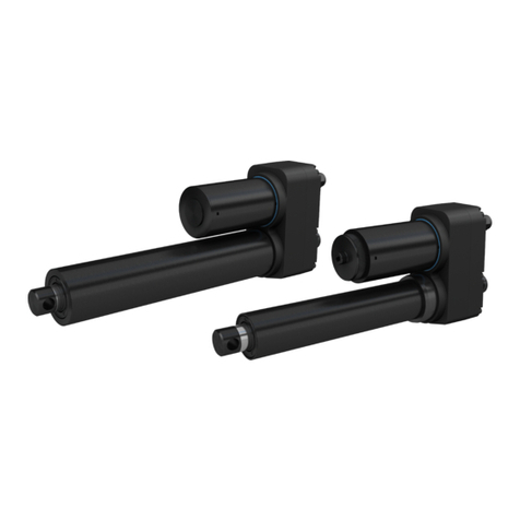
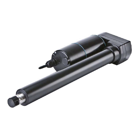
Ewellix CAT 33 User manual

CATEGORY
MAX 2 LINESINSTALLATION, OPERATION AND MAINTENANCE MANUAL
CAT 33, 33H
and 32B
Linear actuator


33
Contents
1.0 General information......................................................4
1.1 Information on this manual.............................................4
1.2 Explanation of symbols and signal words ......................4
2.0 Important safety information ...................................... 5
3.0 Intended use..................................................................6
3.1 Duty Factors ...................................................................6
3.1.1 DC Versions .............................................................6
3.1.2 AC Versions..............................................................7
3.2 Requirements for correct installation ............................8
4.0 Available versions.........................................................9
5.0 Optional equipment...................................................... 9
6.0 Technical data...............................................................9
7.0 Installation ................................................................... 11
7.1 Actuator assembly......................................................... 11
7.2 Overview of front and rear attachment options............ 12
8.0 Wiring Diagrams .........................................................13
9.0 Encoder E2 .................................................................. 14
9.1 Two-channel quadrature encoder for
CATR/L 32 and 33......................................................... 14
9.2 Technical information.................................................... 14
10.0 Maintenance.............................................................. 16
11.0 Remaining risks......................................................... 16
12.0 Destruction/waste.................................................... 17
WARNING
Read this manual before installing, operating or maintaining this
actuator. Failure to follow safety precautions and instructions could
cause actuator failure and result in serious injury, death or property
damage.

4
CAT 33, 33H and 32B
1.0 General information
1.1 Information on this
manual
This manual provides important information on how to work
with the actuator (also called device or drive) safely and
eciently.
The manual is part of the device, must always be kept in the
device’s direct proximity and should be available for person-
nel to read at any time . All personnel working with the de-
vice must read and understand this manual before starting
any work. Strict compliance with all specied safety notes
and instructions is a basic requirement for safety at work.
Moreover, the accident prevention guidelines and general
safety regulations applicable at the place of use of the de-
vice must also be complied with.
For a better representation of the circumstance of use, the
illustrations used are not necessarily to scale and may vary
from the actual design of the device.
All information and notes in this manual were compiled with
due consideration given to applicable standards and regula-
tions, the present status of technology and our years of
knowledge and experience.
1.2 Explanation of symbols
and signal words
Safety precautions are identied by symbols and signal
words dened on the right hand side of this page.
These signal words indicate the severity of the hazard.
Adhere to these safety precautions and take caution in order
to avoid accidents that may result in personal injuries or da-
mage to property.
DANGER
Indicates a dangerous situation, which
will lead to death or serious personal
injury, if the precautionary measures are
ignored.
WARNING
Indicates a dangerous situation, which
can lead to minor or moderate injury or
property damage, if the precautionary
measures are ignored.
CAUTION
Indicates a dangerous situation, which
can lead to minor or moderate injury, if
the precautionary measures are ignored.
NOTICE
Indicates information considered
important, but not hazard-related (e.g.
messages relating to property damage).
NOTE
Emphasizes useful hints and
recommendations as well as information
for ecient and trouble-free operation.

5
2.0 Important safety information
The actuator is assembled and delivered by Ewellix accord-
ing to the ordering key. Modication of the actuator is not al-
lowed in any way. Any modication will void the warranty
and could create a safety hazard. Ewellix disclaims any and
all liability or responsibility for the modied product and for
any claims, demands or causes of action for damage or for
personal injury resulting from modication and/or use of
such product. In addition, if the actuator has been disas-
sembled, misused or altered without prior written authorisa-
tion, warranty will be voided. These installation instructions
are part of the actuator and should be kept together with all
relevant documentation regarding the application in which it
is used.
The following are important safety precautions that must be
followed during installation:
• All electrical installation and maintenance should be car-
ried out by qualied personnel.
• Terminate power supply to the actuator before installation
or maintenance.
• Make sure that the actuator is not under load or in tension
before installation or maintenance.
• Use the appropriate safety equipment when installing/re-
pairing the actuator.
• When connecting the actuator, make sure that the power
supply corresponds to what is required in the technical
specications. See section 5 below.
WARNING
When heavy load and high duty factor is used, motor and
surrounding components can get hot.

6
CAT 33, 33H and 32B
6
3.0 Intended use
The actuator is intended to be used for linear movements
and axial load only, pushing and/or pulling, and intermittent
duty. The actuator is designed to be used in an industrial en-
vironment and is dened as a ”partly completed machine”,
meaning it must be incorporated in a safe way into its i
tended machine.
The actuator can not be used for hoisting people.
3.1 Duty Factors
Permitted load is related to the duty factor and the ambient
temperature where the actuator operates. Consequently,
when load and/or temperature raise the duty factor must be
lowered to prevent the actuator from being damaged.
CAUTION
If the recommended duty factor is exceeded the actuator may be
overheated and damaged.
Duty factor is dened as amount of time running under load
vs. total cycle time.
By using the formula below one can calculate the duty and
determine the risk of overheating.
Duty factor % = x 100
N
N + R
N = running under load
R = rest period
N+R = total cycle time
N
N+R
R
Permitted load for DC actuators at a specic duty factor is
expressed in percentage of maximum dynamic load capac-
ity, ⮑table 1.
Do not permitt the motor surface temperature to exceed
70°C.
CAUTION
Caution, it may take several hours for the actuator to be
overheated.
WARNING
If temperture is permitted to raise uncontrolled the actuator can
eventually cause re.
3.1.1 DC Versions
Table 1
Actuator Max duty factor at max dynamic load
and at 20 °C (68 °F)
CAT 33 15%
CAT 32B 20%
CAT 33H 20%

7
3.0 Intended use
7
3.1.2 AC Versions
E110C E220C motors
Below diagrams show how the actuators will function when
using dierent capacitors with single phase motor E220C &
E110C.
800
500
300
0
1 2 4
0 10 20 30 40 50 60 70 80 90 100
1 600
1 050
500
2 400
1 600
800
1 000
650
350
0
1 2 4
0 10 20 30 40 50 60 70 80 90 100
2 000
1 500
650
3 000
2 000
1 000
1 500
900
500
0
1 2 4
0 10 20 30 40 50 60 70 80 90 100
2 500
1 500
900
3 500
2 500
1 500
500
0
1 2 4
0 10 20 30 40 50 60 70 80 90 100
9001 200 500
350
250
0
1 2 4
0 10 20 30 40 50 60 70 80 90 100
900
500
300
1 200
600
500
F[N] Gear
Duty factor [%]
25 µF (E110)
16 µF (E110)
12 µF (E110)
F[N] Gear
Duty factor [%]
6 µF (E220)
4 µF (E220)
3 µF (E220)
F[N] Gear 6 µF (E220)/
25 µF (E110)
4 µF (E220)/
16 µF (E110)
3 µF (E220)/
12 µF (E110)
Duty factor [%]
F[N] Gear
25 µF (E110)
Duty factor [%]
F[N] Gear
Duty factor [%]
6 µF (E220)
4 µF (E220)
3 µF (E220)
CAT 33
120 V AC
CAT 32B
230/120 V AC
CAT 33H
120 V AC
CAT 33H
230 V AC
CAT 33
230 V AC

8
CAT 33, 33H and 32B
8
a
a
F
F F
Angle α = max 30°
Fig. 1
Fig. 2
3.2 Requirements for
correct installation
• Maximum angle between the actuator’s attachment and
the rear mounting attachment must not exceed 30°
(⮑ g. 1).
• The surface to which the actuator is attached must be able
to withstand the force applied by the actuator.
• Ensure that the applied force on the attachments is always
centered on the actuator. (⮑ g. 2).
WARNING
Do not exceed the actuator’s rated load limits. Doing so can
result in serious injury and/or property damage. For technical
data on load limits, see section 5 below.
CAUTION
Avoid running the actuator into the mechanical end position.
Repeatedly running into the mechanical end position may
damage the actuator or shorten its lifespan.

9
4.0 Available versions
9
All values for standard actuators are tested under the
following conditions:
• Temperature + 20 °C (68 °F)
• Stabilized voltage
• Compression load
6.0 Technical data
4.0 Available versions
CAT 32B, 33 and 33H are available in the following versions:
• 12/24 V DC
• 120/230/400 V AC
• Five types of front attachments and four types of rear
attachments.
• Encoder for digital feedback signal.
5.0 Optional equipment
• Control unit
• Limit switches
• Encoder E2 (⮑section 8)
More information is available on ewellix.com

10
CAT 33, 33H and 32B
DC versions
Description Unit –
Rated push load N 1 000 to 4 000
Rated pull load N 1 000 to 4 000
Speed (at full load) mm/s 5 to 521)
Stroke mm 50 to 700
Retracted length mm S+167/175/2062)
Voltage V DC 12 or 24
Power consumption WN/A
Current consumption 12 V DC A 18
24 V DC A 9
24 V DC A 5 (for motors C24CW
and D24CW)
Duty cycle %20
Ambient temperature °C –20 to +50
Type of protection IP 44/661)
Weight kg 2 to 3,5
DC versions
Description Unit –
Rated push load N 400 to 1 200
Rated pull load N 400 to 1 200
Speed (at full load) mm/s 17 to 1931)
Stroke mm 100 to 400
Retracted length mm S+150/158/1892)
Voltage V DC 12 or 24
Power consumption WN/A
Current consumption 12 V DC A 18
24 V DC A 9
24 V DC A 5 (for motors C24CW
and D24CW)
Duty cycle %20
Ambient temperature °C –20 to +50
Type of protection IP 44/661)
Weight kg 2 to 2,7
DC versions
Description Unit –
Rated push load N 800 to 3 000
Rated pull load N 800 to 3 000
Speed (at full load) mm/s 5 to 521)
Stroke mm 100 to 400
Retracted length mm S+150/158/1892)
Voltage V DC 12 or 24
Power consumption WN/A
Current consumption 12 V DC A 18
24 V DC A 9
24 V DC A 5 (for motors C24CW
and D24CW)
Duty cycle %15
Ambient temperature °C –20 to +50
Type of protection IP 44/661)
Weight kg 2 to 2,7
AC versions
Description Unit –
Rated push load N 800 to 3 000
Rated pull load N 800 to 3 000
Speed (at full load) mm/s 5 to 241)
Stroke mm 100 to 400
Retracted length mm S+150/158/1892)
Voltage V AC 120, 230. 400
Power consumption 120 V AC W 98 (brake 133,2 W)
230 V AC W 92 (brake 117,3 W)
400 V AC W 80
Current consumption 120 V AC A 0,82 (brake +0,29 A)
230 V AC A 0,4 (brake +0,11 A)
400 V AC A 0,2
Duty cycle %30
Ambient temperature °C –20 to +50
Type of protection IP 20/54/55
Weight kg 2 to 2,7
AC versions
Description Unit –
Rated push load N 1 500 to 3 500
Rated pull load N1 500 to 3 500
Speed (at full load) mm/s 6,5 to 321)
Stroke mm 50 to 700
Retracted length mm S+167/175/2062)
Voltage V AC 120, 230. 400
Power consumption 120 V AC W 98 (brake 133,2 W)
230 V AC W 92 (brake 117,3 W)
400 V AC W 80
Current consumption 120 V AC A 0,82 (brake +0,29 A)
230 V AC A 0,4 (brake +0,11 A)
400 V AC A 0,2
Duty cycle %30
Ambient temperature °C –20 to +50
Type of protection IP 20/54/55
Weight kg 2 to 3,5
AC versions
Description Unit –
Rated push load N 500 to 1 200
Rated pull load N500 to 1 200
Speed (at full load) mm/s 20 to 901)
Stroke mm 100 to 400
Retracted length mm S+150/158/1892)
Voltage V AC 120, 230. 400
Power consumption 120 V AC W 98 (brake 133,2 W)
230 V AC W 92 (brake 117,3 W)
400 V AC W 80
Current consumption 120 V AC A 0,82 (brake +0,29 A)
230 V AC A 0,4 (brake +0,11 A)
400 V AC A 0,2
Duty cycle %30
Ambient temperature °C –20 to +50
Type of protection IP 20/54/55
Weight kg 2 to 2,7
CAT 33
CAT 32B
CAT 33H
CAT 32B
CAT 33H
CAT 33
1) Depending on selected motor.
2) Dimension depends on selected front attachment.

11
7.0 Installation
7.0 Installation
Only qualied personnel are allowed to install this equip-
ment. Contact Ewellix for further information.
WARNING
Do not exceed the actuator’s load limits. Doing so can result in
serious injury and/or property damage. For technical data on
load limits, see section 6, page 9.
7.1 Actuator assembly Fig. 1
1
6
7
8
2
3
4
5
Description of the mechanical installation
procedure.
1. Screw counter nut (3) onto the actuator front attachment (4)
2. Screw the front attachment (1, 2) onto the actuator’s front
attachment (4), making sure that the engaged thread
length is, at a minimum, the diameter of the thread which
is 12 mm.
3. Tighten the counter nut (3) onto the front attachment (1)
with 20 Nm.
4. Disassemble pin (2) from front attachment (1).
5. Install the actuator onto the front and rear attachments.
Mount the pin (2) onto the front attachment (1). Mount
rod (7) with safety pins (6) onto the rear attachments (5)
and (8).
While dismounting follow the steps in the order from (6) to (1).

12
CAT 33, 33H and 32B
7.2 Overview of front and
rear attachment options
Fig. 2
12
3
4
5
6
7
8
9
10
11
12
13
14
1. Front attachment (accessories) 576-32
2. Safety pin (part of 576-32)
3. Nut M12
4. Front attachment (accessories) 575-32
5. Actuator front attachment option G3
6. Actuator front attachment option G5
7. Actuator front attachment option G4
8. Actuator front attachment option G1/G2
9. Actuator rear attachment A1/A2
10. Actuator rear attachment K1/K2
11. Mounting rod (supplied with rear attachment A1/A2)
12. Safety pin (supplied with rear attachment A1/A2)
13. Attachment rear (accessories) 580-32
14. Attachment rear (accessories) 582-32

13
8.0 Wiring Diagrams
Fig. 3
Connecting diagram - AC version
Single phase
L1
N
PE
120/230 V AC
L1
L2
L3
N
PE
400 V AC
2
CW 0Q1 Q2
Q2 Q1
M
Q1
Q2
W1 V1 U1
+140 °C
CCW
1
3~
Black
Blue
White
Brown
Red
Red
Black
Black
Limit
switch
Limit
switch
+
2
13 2
13
M
12/24 V DC
21
Fig. 4
Connecting diagram - DC version
WARNING
• All electrical installation/maintenance should be carried out by
qualied personnel.
• Isolate the power before installation or maintenance. Use the appro-
priate safety equipment when installing/repairing the equipment.
• When connecting this equipment to the electrical supply, make
sure that it corresponds to the one described in the technical
specications.
• For complete installation instructions regarding Ewellix limit
switch, see separate installation instructions.
8.0 Wiring Diagrams
3 phase

14
CAT 33, 33H and 32B
9.0 Encoder E2
9.1 Two-channel
quadrature encoder for
CATR/L 32 and 33
• The encoder is available for all motor types and screw
pitches in the CAT-modular range
• The encoder consists of two parts; one rotating magnet on
the motor drive shaft, and one circuit board (PCB) assem-
bled on the motor’s opposite side.
• The rotating permanent magnet has four poles (2N and 2S)
and during one motor revolution, two pulses are generated
in each channel.
• The output signals, channel 1 and 2, are phase-shifted ±90°
• Supply voltage range is from 5 to 24 V DC
• Temperature range is from –20 to +50 °
9.2 Technical information
Channel 1 (reference)
Channel 2 moving direction
Outwards CATR
Inwards CATL
Channel 2 moving direction
Inwards CATR
Outwards CATL
(1) Output signals when the actuator is moving either out-
wards or inwards.
0° 360° 720°
90°
90°
U
U
U
1 rev. for the magnet
Fig. 5

15
9.0 Encoder E2
1) The alternatives in wire color for output signals channel 1 and 2 mean that the actuator
has been assembled as CATR (right) or CATL (left). The wire is delivered with stripped
ends (no connector).
+V
Encoder
Supply
POS
Output
signal Ch X
Supply
GND
GND
1,8 k Ω
Fig. 6
Encoder output circuitry – open drain with pull-up
Table 2
Movement resolution
Actuator Gear option Pulse at 1
mm stroke
Resolution per
pulse [mm]
CAT 33 116,67 0,06
CAT 33 28,33 0,12
CAT 33 44,17 0,24
CAT 33H 14,00 0,25
CAT 33H 22,00 0,50
CAT 33H 41,00 1,00
CAT 32B 112,50 0,08
CAT 32B 26,25 0,16
CAT 32B 43,13 0,32
Table 3
Recommended operating ratings
Parameter Value
Temperature range –20 to +50 °C
Supply voltage range +5 to +24 V DC ±5%
Current sink capability Max 20 mA
Table 4
Wire color coding (colors according to DIN 47100)
Parameter Value
Brown Supply voltage GND (-)
White Supply voltage POS (+)
Green (L)1) alt. Yellow (R)1) Output signal channel 1
Yellow (R)1) alt. Green (L)1) Output signal channel 2

16
CAT 33, 33H and 32B
10.0 Maintenance
Interval Maintenance work
Daily Check actuator for visible damage
Clean o dust and dirt if necessary
Monthly Check attachments and tighten if necessary
Check that cables are not damaged, replace if necessary
Check optional equipment for visible damage, replace if necessary
Functional check of operation
Every 6 months A few drops of oil should be applied to the adjustment tube
Annually Check labels
Check electrical connections
Table 5
11.0 Remaining risks
Regardless if the actuator has been installed according to
this instruction some remaining risk excist.
Take note of these points during the lifespan of the actuator:
If any unnormal noise occure stop the actuator directly.
If the actuator has been subjected to excessive load, even
for a short time, be aware of unnormal noise or ”wobbling
movement”.
Do not operate the brake on its own when actuator is under
load.

17
12.0 Destruction/waste
As majority of the actuator is made of steel and stainless
steel some amount of grease/oil can be found inside. The
motor and some assesories, like limit switch and encoder is
considered electrical waste.
Check for local rules and information on how to despose the
actuator and its parts.
Keep this information for future reference. Please contact
your local Ewellix sales oce if you need more information
or spare parts.
Please check ewellix.com for relevant addresses.

ewellix.com
© Ewellix
All contents of this publication are the property of Ewellix, and may not be re-
produced or given to third parties (even extracts) without permission. Although
great care has been taken in the production of this catalog, Ewellix does not
take any responsibility for damage or other loss resulting from omissions or ty-
pographical errors. The photo may dier slightly in appearance from the actual
product. Due to continuous improvements being made in our products, the prod-
uct’s appearance and specications are subject to change without notice.
PUB NUM TC-08016-EN-April 2020
This manual suits for next models
2
Table of contents
Other Ewellix Controllers manuals
Popular Controllers manuals by other brands

Honeywell
Honeywell DBC2000 Series Product handbook

Aprimatic
Aprimatic ST450N Fitting instructions

LEGRAND
LEGRAND 0 883 27 quick start guide

Steca
Steca TR A301 Installation and operating instructions

PSC Solar
PSC Solar YQPV-HP360V/100A Installation and operating instructions

TSi Power
TSi Power ATS-500 Series installation instructions