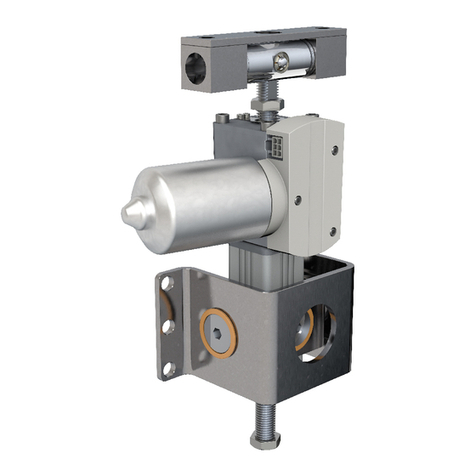
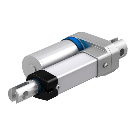
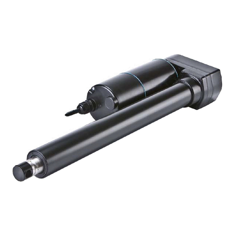
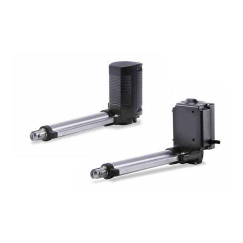
Ewellix SRSA Series User manual

CATEGORY
MAX 2 LINESINSTALLATION, OPERATION AND MAINTENANCE MANUAL
Electric cylinders
SRSA, SVSA and
SLSA


33
Contents
1.0 Introduction – general safety instructions ................4
1.1 Structure of safety instructions .......................................4
1.2 Manual use ......................................................................4
1.3 General safety instructions .............................................4
1.4 Exclusion of liability.........................................................5
1.5 Future changes to user manual ......................................5
2.0 General notes................................................................6
2.1 General description of system components...................6
2.2 Operating principle .........................................................8
2.3 Detailed description of supplied product .......................9
2.4 Designation ................................................................... 10
2.5 Nameplate ..................................................................... 12
2.6 Performances, operation limits and operation
environment ......................................................................... 12
2.7 Storage conditions ........................................................ 12
2.8 Disposal......................................................................... 12
2.9 Warrenty ........................................................................ 12
3.0 Installation – general recommendations.................13
3.1 Important notes ............................................................. 13
3.2 Mechanical installation ................................................ 13
3.2.1 Cylinder dimensions – Cylinder drawing................ 13
3.2.2 Visual cylinder position – Lt0 and Lt denition ........ 14
3.2.3 Handling – Transportation ...................................... 15
3.2.4 General recommendations for installation............. 15
3.3 Electrical installation ..................................................... 15
3.3.1 Motor....................................................................... 15
3.3.2 Cables for motor..................................................... 15
3.3.3 Limit switches......................................................... 15
3.3.4 Home switch ........................................................... 18
3.3.5 Temperature sensor................................................20
3.3.6 Cables for sensors.................................................. 20
3.3.7 Additional brake mounted on screw ......................20
3.3.8 Automatic lubrication pump ...................................21
3.3.9 Servoamplier.........................................................21
4.0 Commissioning ...........................................................22
4.1 O ve r vi ew ........................................................................22
4.2 General recommendations for use ...............................23
4.3 How to dene zero reference........................................23
4.4 How to check position control behaviour – rst
approach.............................................................................. 24
4.5 Position control parameters – to be known.................. 26
5.0 Maintenance, upkeep and routine checks ..............27
5.1 Ewellix maintenance service .........................................27
5.2 Lubrication – detailed description ................................27
5.2.1 Roller screw (or ball screw).....................................28
5.2.2 Bearings..................................................................28
5.2.3 Prole rail guides ....................................................28
5.2.4 Spherical plain bearing...........................................29
5.2.5 Gear ........................................................................29
5.3 Routine checks – detailed description .........................29
5.3.1 Additional brake mounted on screw.......................29
5.3.2 Belt..........................................................................29
6.0 Malfunctions................................................................30
6.1 Mechanical malfunctions ..............................................30
6.2 Inspections prior to rst operation ............................... 31
6.3 Before requiring Ewellix assistance.............................. 31

4
Electric cylinders SRSA, SVSA and SLSA
4
1.0 Introduction – general safety
instructions
1.1 Structure of safety
instructions
To best warn the user, depending on the nature of the dan-
ger, safety instructions will be written as follows.
1.2 Manual use
This manual gives information and advice for the commis-
sioning and maintenance of Ewellix modular cylinders from
the SRSA, SLSA, SVSA range of products that will minimize
the risk of injury and property damage.
This document is intended for all persons who are involved
with the installation, commissioning or maintenance of these
products.
NOTE
In the electronic document, hypertext links have been created
to allow faster browsing inside the manual. To use these, please
press CTRL key and while CTRL key is pressed, click on the
hypertext link. To come back, please press ALT key and while
ALT key is pressed, press on “left arrow” key.
Generally, all titles from table of contents are hypertext links. All
other hypertext links are pointed out in blue.
1.3 General safety
instructions
DANGER
In operation, Ewellix cylinders could make parts move and could
have hot surfaces or parts fed by electrical current, depending
on the situation. Serious or fatal injuries or property damage will
occur if the information or precautionary measures given in this
manual aren’t followed.
Generally, all works related to transportation, setup/mounting
(mechanical and electrical), startup, maintenance or storage
have to be carried out by qualied personnel in full compliance
with relevant regulations.
DANGER
Indicates an imminently hazardous
situation. If precautionary measures
aren’t taken, it could result in death,
serious injury or property damage.
WARNING
Indicates a potentially hazardous
situation. If precautionary measures
aren’t taken, it could result in death,
serious injury or property damage.
CAUTION
Indicates a potentially hazardous
situation. If precautionary measures
aren’t taken, it could result in minor or
moderate injury.
NOTE
Points to note, tips, advice or information
for ecient operation without any
problem.

5
1.0 Introduction – general safety instructions
1.4 Exclusion of liability
Ewellix does not assume liability for injury to persons or
damage to equipment or property resulting from non-obser-
vance of these operating instructions. In such cases, any
liability is excluded.
1.5 Future changes to user
manual
To constantly improve the quality of its products, Ewellix re-
serves the right to modify this manual without informing its
customers. It is the responsibility of the customer to have
the current release of the manual so that the user will benet
from the latest information and advice. For more details,
please contact your Ewellix sales representative.
In any event, Ewellix won’t be liable for any adverse conse-
quences to the Ewellix product user or any property be-
cause of user manual modication.

6
Electric cylinders SRSA, SVSA and SLSA
6
2.0 General notes
2.1 General description of
system components
Generally, the scope of supply of Ewellix cylinders includes:
• Cylinder
• Motor power cable
• Motor sensor cable
• Motion controller
• Electronic interface to make connection between PC and
motion controller.
To know the exact denition of Ewellix supply, please read
paragraph 2.3 Detailed description of supplied product.
The general drawing below illustrates the Ewellix electrome-
chanical cylinder’s relationship with the user’s environment:

7
2.0 General notes
7
Customer main controller /PLC
Customer electrical cabinet
Sensors (limit switches, home switch)
1. Motor power cable.
2. Motor sensor cable.
3. Possible communications with external environment – if
necessary – : analog/digital inputs/outputs, eldbus.
4. Connection with PC (temporarily necessary for setting up)
F3
F2
F5
F4
F1
7
STU
4
JKL
ESC
+/-
«
1
ABC
8
VWX
5
MNO
←
0
π
2
DEF
9
YZ
6
PQR
RET
–
3
GHI
MEMFIX
ESC RET
F3
z
F2
z
F1
z
F4
z
F5
z
3 x 400 V AC
1 x 24 V DC
3
4
2
1

8
Electric cylinders SRSA, SVSA and SLSA
8
2.2 Operating principle
The operating principle of Ewellix electromechanical cylin-
ders is described by the cinematic drawing below (estab-
lished in accordance with NF EN ISO 3952-1 standard).
The operating principle of Ewellix
electromechanical cylinders
J1
J1J2
J3
wa
wb
Sc
x
1
2
3
4
5
Anti-rotation system
Comments
1 Motor rotor
ωaRotating speed of motor shaft
ωbRotating speed of roller screw or ball screw
2 Gear system between motor shaft and roller screw (or
ball screw) shaft. r is gear ratio.
ω
a
r = –––
ω
b
3 Roller screw or ball screw = screw gear changing
rotation of screw (green color) into translation of nut
and pushing tube of cylinder (red color).
4 Pushing tube of cylinder
Sc Translation speed of pushing tube
x Translation move of pushing tube
5 Anti-rotation of pushing tube. Depending on cylinder
denition, this system is integrated into the cylinder or
located on the customer’s machine.
Description of kinematic joints
J1Revolute joint
J2Screw joint
J3Prismatic joint
J1
J2
J3

9
2.0 General notes
9
Relationships to be known
For each motor revolution cylinder moves x millimetres, x
dened as follows:
ph
x = –––
r
x Cylinder move
phRoller or ball screw lead
Depending on case, r denition can change:
• Cylinder with motor in line without gear
r = 1
• Cylinder with motor in line and gear
r = rgwith rggear ratio
• Cylinder with motor in parallel without gear
r = rbwith rbbelt system ratio
• Cylinder with motor in parallel and gear
r = rb· rg
2.3 Detailed description of
supplied product
Generally, a detailed description of the supplied product is
given by the two following documents (called “documents
for approval”):
• Technical description
• Cylinder drawing
IMPORTANT:
Before starting cylinder commissioning, these two docu-
ments must be read. If there is a problem, please make con-
tact with your local Ewellix representative.

10
Electric cylinders SRSA, SVSA and SLSA
10
2.4 Designation
Two designations:
• Designation for linear unit (=actuator without motor).
Example: SRSA-U-4810-0200-TRAF-N
• Designation for complete actuator (=actuator with motor
and servoamplier).
Example: SRSA-U-4810-0200-TRAF-L010LA21BYA1
The meaning of linear unit designation is:
The meaning of complete actuator designation on the next page.
S R S A - U - 4 8 1 0 - 0 2 0 0 - T R A F - N
Type
R Planetary roller screw
VRecirculating roller screw
L Long lead ball screw
Linear unit only
Screw diameter
Screw lead
Stroke
Rear attachment
TTrunnions
ZSpecial
NNo attachment
Front attachment
R Rod end
F Rod end with fork
ZNon standard
NNo attachment (female thread)
Anti-rotation
AAnti-rotation
NNo anti-rotation
Limit switches
F 2 limit switches and 1 home switch
S 2 limit switches only
M 1 limit switch and 1 home switch
L 1 limit switch only
H 1 home switch only
N No switch
Motor interface
NNo interface
LInline interface (on request)
P Parallel interface (on request)

11
2.0 General notes
11
Type
RPlanetary roller screw
VRecirculating roller screw
L Long lead ball screw
Servomotor
Screw diameter
Screw lead
Stroke
Rear attachment
TTrunnions
ZSpecial
NNo attachment
Front attachment
R Rod end
F Rod end with fork
ZNon standard
NNo attachment (female thread)
Anti-rotation
AAnti-rotation
NNo anti-rotation
Limit switches
F 2 limit switches and 1 home switch
S2 limit switches only
M 1 limit switch and 1 home switch
L 1 limit switch only
H1 home switch only
N No switch
Interface and gear ratio
If required, see Ewellix catalogue IL-06011 for more details
Motor
If required, see Ewellix catalogue IL-06011 for more details
Feedback
1Resolver
2Absolute encoder Hiperface
3Absolute encoder Endat
EM brake
B Brake 24 V DC
NNo brake
Motor drive
YDrive included
N No drive
Drive eldbus
ACanOpen
BDeviceNet
CEtherCAT
DEthernet
EPowerlink MN/CN
FPowerlink CN
GProbus
HPronet
NNo eldbus
Power and signal cables
1 5 m
210 m
315 m
4 20 m
NNo cable
S R S A - S - 4 8 1 0 - 0 2 0 0 - T R A F - L 0 1 0 L A 2 1 B Y A 1

12
Electric cylinders SRSA, SVSA and SLSA
12
2.5 Nameplate
Made in Frabce
by Ewellix France SAS
Type: MM:
Serial no: Weight [kg]:
Weight including motor and gear [kg]:
Type: Cylinder reference
MM: Manufacturing month (month/year)
Serial no: Cylinder serial number
Weight: Cylinder weight
Weight including Cylinder weight when supplied with motor and
motor and gear: possibly with gear
2.6 Performances,
operation limits and
operation environment
For more details, please read the Ewellix sales oer and
other documents for approval. The cylinder’s performance
and operational limits and operating environment are de-
scribed in the technical requirements that dene the cylinder
selection.
2.7 Storage conditions
If the cylinder has to be stored for a long time (example: cyl-
inder as a spare part), the following conditions must be
observed:
• Cylinder has to be stored in horizontal position indoors
with an ambient temperature between 15 and 40 °C.
• Cylinder has to be packed in the retracted position inside a
plastic lm with desiccant to protect the cylinder from hu-
midity and condensation.
A cylinder that has been stored under the conditions de-
scribed above for less than one year could be used by fol-
lowing the general recommendations for use (⮑ 4.2
General recommendations for use, page 23).
If storage time exceeds one year, re-lubricate the cylinder
before it is rst started (please read paragraph 5
Maintenance – upkeep – routine checks, to know which
parts are to be lubricated and how they are to be lubricated).
Then, cylinder can be used by following general recommen-
dations for use (⮑ 4.2 General recommendations for use,
page 23).
After three years of storage, we recommend that the cylinder
is returned to Ewellix and a level one maintenance service
be performed (⮑ 5.1 Ewellix Maintenance service,
page 27).
NOTE
If an automatic lubrication system is installed, it is possible to
unplug it temporarily so that re-lubrication can be done with a
manual grease pump as explained on this page.
2.8 Disposal
Dispose of cylinders in accordance with applicable regula-
tions and considering the dierent requirements for each
material:
• Iron
• Aluminium
• Copper
• Plastic
• Electronic components
• Oil and grease (not mixed with solvents)
To know the exact denition of Ewellix supply, please read
paragraph 2.3 Detailed description of supplied product.
2.9 Warrenty
IMPORTANT:
Manufacturer’s warranty is null and void if the cylinder is dis-
assembled by end-user.
For any other information concerning warranty, please con-
tact your local Ewellix representative.

13
3.0 Installation – general recommendations
13
3.0 Installation – general
recommendations
3.1 Important notes
DANGER
Some components integrated into the Ewellix scope of supply
are “products bought on catalogue”. This means that the design
and manufacturing of these components haven’t been done by
Ewellix.
For all these “products bought on catalogue”, it’s the user’s
responsibility to read the associated manufacturer’s user manual
before starting to install or to use the product.
WARNING
Risk of serious or fatal injuries by crushing because of
vertical load fall.
Do not use the brake (of the motor or an additional brake) to hold
a vertical load while an operator is under the load. Generally,
the holding torque of the brake is created by means of friction
discs and does not provide a positive lock. In any event, lock the
vertical load in position by another means or move and stop the
vertical load at the bottom position which is safe.
WARNING
Risk of serious or fatal injuries by crushing because of
unintentional cylinder start-up.
Before starting any work on actuator, isolate the motor, brake
and fan (if installed) from the power supply and safeguard them
using lockout/tagout procedures against unintentional re-start.
WARNING
During operation, the cylinder surface temperature can reach
high values. There is a risk of burns or re. Before any work on
the actuator, let it cool down.
3.2 Mechanical
installation
3.2.1 Cylinder dimensions – Cylinder
drawing
To know the cylinder dimensions and the denition of its at-
tachments, please look at cylinder drawing. The denition of
drawing cylinder is given in paragraph ⮑ 2.3 Detailed
description of supplied product, page 9.

14
Electric cylinders SRSA, SVSA and SLSA
14
3.2.2 Visual cylinder position – Lt0 and Lt
denition
During mechanical installation or cylinder operation, it is
sometimes required to know the cylinder position in relation
to the “zero” position given in the cylinder drawing.
To do this, it’s rst required to know Lt0 (=length of pushing
tube which is visible when cylinder is in the “zero” position
on the cylinder drawing – please have a look at the cylinder
drawing) – as examples, see below some drawings illustrat-
ing Lt0 denition.
Lt0
Lt0
Then, it’s required to measure Lt: equivalent dimension of Lt0
when cylinder is in any position.
Lt
Then, cylinder position in relation to the “zero” position given
in the cylinder drawing is equal to Lt-Lt0.

15
3.0 Installation – general recommendations
15
3.2.3 Handling – Transportation
Observe relevant transport regulations during
transportation.
When the shipment is received, immediately check that no
damage has been done during transportation. If not, imme-
diately inform the shipping company and Ewellix. If the ship-
ment has been damaged, do not commission it.
Use suitable load suspension devices for transport and
assembly.
Weights of cylinder and any gear and motor are indicated on
corresponding nameplates. If not, please read the technical
documentation of the corresponding manufacturer.
In case of a problem, please contact your local Ewellix
representative.
NOTE
During actuator handling, please take care not to damage the
limit switches and home switch (if these options have been
taken).
3.2.4 General recommendations for
installation
1. When mounting the cylinder, check that all parts to
which it is xed are correctly aligned. This should be
done throughout the complete stroke. Note: Poor align-
ment will reduce the life of the cylinder.
2. Radial load or bending torque must not be applied to the
cylinder pushing tube. Otherwise cylinder lifetime might
be drastically reduced.
3. Avoid shocks on the pushing tube. Do not hit it with a
hammer.
4. Check that cylinder can move freely and there is no ob-
struction over the full stroke.
5. Do not modify any part of cylinder
6. Do not add any part/component on cylinder
NOTE
If actuator has no anti-rotation on the force tube, it is possible to
extend or retract by turning force tube by hand.
3.3 Electrical installation
3.3.1 Motor
Generally, please read the technical documentation from
the motor manufacturer to know how to properly install the
motor. The details concerning the motor can be found on its
nameplate.
If the motor manufacturer doesn’t supply paper documenta-
tion or documentation CD-ROM, it means that a user man-
ual can be downloaded from the manufacturer’s web site.
In case of a problem and if motor has been sold by Ewellix,
please contact your local Ewellix representative. Otherwise,
please contact motor supplier.
DANGER
During and after operation, some parts of the cylinder carry
dangerous voltages. Electric shock hazard. Risk of serious or
fatal injuries.
Strictly observe the safety instructions in this manual and
the safety instructions of manuals associated with each
commissioned equipment (motor, servoamplier, etc).
Do not unplug motor connectors before switching o the power
supply of the corresponding servoamplier. First unplug the
signal connector and then the power connector.
Motor rotation can create voltage. Do not touch connector pins.
3.3.2 Cables for motor
If motor cables are included in Ewellix supply, please read
the motor technical documentation or servoamplier techni-
cal documentation to nd the technical description and con-
nection drawing of supplied cables. Cable reference is writ-
ten on the cable itself or on its packaging.
In case of a problem, please contact your Ewellix local
representative.
3.3.3 Limit switches
3.3.3.1 Description
If this option has been taken, the following information will
be necessary for connecting the limit switches correctly:
Manufacturer: IFM Electronic (or equivalent)
Manufacturer reference: IFC207 (or equivalent)
Sensor type: Inductive
Technology: DC PNP
Output: Normally closed
Supply voltage (V DC): 24
Consumption (mA): <10 (with 24 V DC)
Max. current output (mA): 100
Connection: M12x1 plug
WARNING
All technical data given here have been extracted from
manufacturer’s catalogue when this manual was edited. They are
given for information only.
If limit switch manufacturer changes this data, Ewellix is not
responsible for any problem arising from such changes. Please
check with limit switch manufacturer just before installing limit
switch.
1
L+
L–
2
3
1
43
2
Please have a look at the servoamplier manufacturer’s
technical documentation to know what digital input can be
used for connecting limit switches.

16
Electric cylinders SRSA, SVSA and SLSA
16
3.3.3.2 Mounting instructions of limit switch
for “retracted position”
If the limit switch for “retracted position” has been removed,
please follow these instructions to mount it again correctly:
Limit switch for “retracted position”
Roller screw
nut (back side)
It’s this surface that’s detected by
the limit switch. In that view and in
this position, Ltequals to Lt0.
1. Move cylinder so that Lt= Lt0 (±0,5 mm).
NOTE: To know the denition of Ltand Lt0, please look at
paragraph ⮑ 3.2.2 Visual cylinder position – Lt0 and Lt
denition, page 14.
2. Screw in the limit switch with care by hand into the dedi-
cated threaded hole until it touches the roller screw nut
(see cross-section view above). Then, unscrew the limit
switch to create a gap between it and the rollerscrew nut.
Stop unscrewing just before the limit switch stops
detecting.
3. Fix the limit switch in this position by tightening the coun-
ter-nut (tightening torque: 7 Nm).
4. In this position, check that the limit switch detects the
roller screw nut.
5. Move the cylinder so that Lt= Lt+ 3 mm (±0,5 mm). In
this position, please check that nothing is detected by
the limit switch.

17
3.0 Installation – general recommendations
17
3.3.3.3 Mounting instructions of limit switch
for “extended position”
If the limit switch for “retracted position” has been removed,
please follow these instructions to mount it again correctly:
Limit switch for “extended position”
Roller screw
nut (front side)
It’s this surface that’s detected by the
limit switch. In that view and in this
position, Ltequals to Lt0 + cylinder stroke.
1. Move the cylinder so that Lt=Lt0 + cylinder stroke
(±0,5 mm).
NOTE: To know the denition of Ltand Lt0, please look at
paragraph ⮑ 3.2.2 Visual cylinder position – Lt0 and Lt
denition, page 14.
2. Screw in the limit switch with care by hand into the dedi-
cated threaded hole until it touches the roller screw nut
(see cross-section view above). Then, unscrew the limit
switch to create a gap between it and the rollerscrew nut.
Stop unscrewing just before the limit switch stops
detecting.
3. Fix the limit switch in that position by tightening the
counter-nut (tightening torque: 7 Nm).
4. In this position, check that the limit switch detects the
roller screw nut.
5. Move cylinder so that Lt= Lt+ cylinder stroke - 3 mm
(±0,5 mm). In this position, please check that nothing is
detected by the limit switch.

18
Electric cylinders SRSA, SVSA and SLSA
18
3.3.4 Home switch
3.3.4.1 Description
If this option has been taken, the following information will
be necessary to connect the home switch correctly:
Manufacturer: IFM Electronic (or equivalent)
Manufacturer reference: IFC204 (or equivalent)
Sensor type: Inductive
Technology: DC PNP
Output: Normally opened
Supply voltage (V DC): 24
Consumption (mA): <10 (with 24 V DC)
Max. current output (mA): 100
Connection: M12x1 plug
WARNING
All technical data given here have been extracted from
manufacturer’s catalogue when this manual was edited. They are
given for information only.
If home switch manufacturer changes this data, Ewellix is not
responsible for any problem arising from such changes. Please
check with home switch manufacturer just before installing home
switch.
1L+
L–
4
3
1
43
2
Please look at the servoamplier manufacturer’s technical
documentation to know what digital input can be used for
connecting the home switch.

19
3.0 Installation – general recommendations
19
3.3.4.2 Mounting instructions of home switch
If the home switch has been removed, please follow these
instructions to mount it again correctly:
It’s this surface that’s detected by the home switch.
In that view and in this position, Ltequals to Lt0 +
cylinder stroke given on the cylinder drawing for
home switch.
Home switch
Roller screw nut
(front side)
1. Move the cylinder so that Lt= Lt0 + cylinder stroke given
on cylinder drawing for home switch (±0,5 mm).
NOTE: To know the denition of Ltand Lt0, please look at
paragraph ⮑ 3.2.2 Visual cylinder position – Lt0 and Lt
denition, page 14.
2. Screw in the limit switch with care by hand into the dedi-
cated threaded hole until it touches the roller screw nut
(see cross-section view above). Then, unscrew the limit
switch to create a gap between it and the rollerscrew nut.
Stop unscrewing just before the limit switch stops
detecting.
3. Fix the limit switch in that position by tightening the
counter-nut (tightening torque: 7 Nm).
4. In that position, check that the home switch detects the
roller screw nut.
5. Move the cylinder so that Lt= Lt0 + cylinder stroke given
on the cylinder drawing for home switch - 3 mm (±0,5
mm). In this position, please check that nothing is de-
tected by the limit switch.

20
Electric cylinders SRSA, SVSA and SLSA
20
3.3.5 Temperature sensor
If this option has been taken, the following information will
be required to make an electrical connection:
Type of temperature sensor: Pt100
Internal wiring mode (=between
plug and temperature sensor): 4 wires (⮑ g. 1)
Possible wiring modes with
external environment: 2, 3 and 4 wires (⮑ g. 1)
Connection: M12x1 plug
Description of internal wiring mode (⮑ g. 2)
Fig. 1
2 wires 3 wires 4 wires
White
White
WhiteWhite
Red Red
Red
Red
Red
Fig. 2
1
43
21. Red
2. Red
3. White
4. White
3.3.6 Cables for sensors
If cables for limit switches and/or home switch and/or tem-
perature sensor have been taken, the following information
will be required to make an electrical connection:
Manufacturer: IFM Electronic (or equivalent)
References: See table below (or equivalent)
IFM Reference Description
EVC005 PUR Cable – length 5 m
EVC006 PUR Cable – length 10 m
EVC086 PUR Cable – length 15 m
EVC087 PUR Cable – length 20 m
EVC088 PUR Cable – length 25 m
Cable diameter: 4,9 mm
Bending radius: min. 10 x diameter of cable
Connection:
On one side: M12x1 plug
On the other side: naked wires
1
2
3
2
34
1
4
BN
WH
BU
BK
BN: brown
WH: white
BU: blue
BK: black
3.3.7 Additional brake mounted on screw
If this option has been taken, the following information will
be required to make an electrical connection:
Manufacturer: see user manual (specic data)
Reference: see user manual (specic data)
Type: see user manual (specic data)
Supply: see user manual (specic data)
Power: see user manual (specic data)
Wire color Description
Green-red or red +U (see user manual (specic data) for
+U denition)
Green-blue or black OV
WARNING
Risk of serious or fatal injuries by crushing because of
vertical load fall.
Do not use the brake (of the motor or an additional brake) to hold
a vertical load while an operator is under the load. Generally,
the holding torque of the brake is created by means of friction
discs and does not provide a positive lock. In any event, lock the
vertical load in position by another means or move and stop the
vertical load at the bottom position which is safe.
WARNING
All technical data given here have been extracted from
manufacturer’s catalogue when this manual was edited. They are
given for information only.
If the brake manufacturer changes this data, Ewellix is not
responsible for any problem arising from such changes. Please
check with the brake manufacturer just before installing the
brake.
WARNING
As a general rule, the brake is not to be used in a dynamic way.
Dynamic breaking will create premature wear which will generate
malfunction of actuator.
This manual suits for next models
2
Table of contents
Other Ewellix Controllers manuals