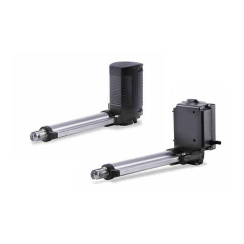
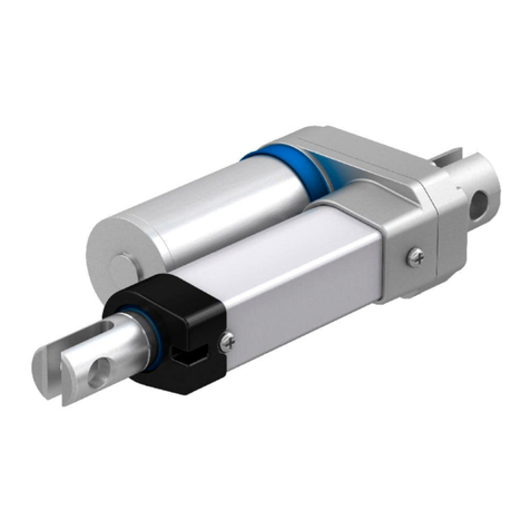
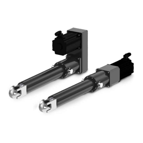
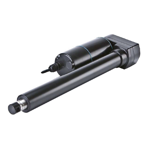
Ewellix CASM-100 User manual

CATEGORY
MAX 2 LINESINSTALLATION, OPERATION AND MAINTENANCE MANUAL
CASM-100


33
Contents
1.0 General information......................................................4
1.1 Information about this manual ........................................4
1.2 Explanation of symbols and signal words ......................4
1.3 Limitation of liability ........................................................4
1.4 Copyright.........................................................................5
1.5 Spare parts......................................................................5
1.6 Warranty terms................................................................5
1.7 Customer service ............................................................5
2.0 Safety .............................................................................6
2.1 Intended use ....................................................................6
2.2 Responsibility of the owner and processor....................6
2.3 Personnel requirements..........................................................6
2.3.1 Qualications ............................................................7
2.4 Safety equipment ............................................................7
2.5 Modications to the device.............................................7
2.5.1 Warning labels...........................................................7
3.0 Technical data...............................................................8
3.1 Operating conditions.......................................................8
3.2 Product labels .................................................................8
3.2.1 Linear unit label.........................................................8
3.2.2 Gearbox label ...........................................................8
4.0 Structure and function.................................................9
4.1 Brief description ..............................................................9
4.1.1 CASM-100 actuator overview....................................9
4.2 Direction of motor during extension of the cylinder.......9
4.3 Overview..........................................................................9
4.3.1 CASM-100 accessories overview.............................9
4.4 Sensor mounting........................................................... 10
5.0 Delivery, packaging and storage .............................. 11
5.1 Safety information for transport.................................... 11
5.2 Delivery inspection........................................................ 11
5.3 Returning actuator to the manufacturer ....................... 11
5.4 Packaging...................................................................... 11
5.5 Storage.......................................................................... 12
5.6 Handling ........................................................................ 12
6.0 Installation and initial operation...............................13
6.1 Installation location ....................................................... 13
6.2 Inspections prior to initial operation............................. 13
6.3 Installation..................................................................... 13
7.0 Operation ..................................................................... 15
7.1 Safety ............................................................................. 15
7.2 Turn on........................................................................... 15
7.3 Turn o........................................................................... 15
7.4 Action before use .......................................................... 15
7.5 Installation instruction CASM-100 ............................... 16
7.5.1 Motor adapter.......................................................... 16
7.5.2 Recommended motors........................................... 16
7.5.3 Coupling installation ............................................... 16
7.5.4 Synchronous Servo Motors .................................... 17
7.5.5 Asynchronous Motors.................................................. 19
7.5.6 Parallel gearbox and motor adapter installation .... 19
8.0 Maintenance................................................................21
8.1 Maintenance plan ..........................................................21
8.2 Maintenance work.........................................................22
8.2.1 Clea ning ..................................................................22
8.2.2 Check sealing function...........................................22
8.2.3 Check of visual condition .......................................22
8.2.4 Relubrication interval..............................................22
8.3 Measures after maintenance completed......................23
8.4 Maintenance checks .....................................................23
9.0 Malfunctions................................................................24
9.1 Malfunction table...........................................................25
9.2 Start of operation after xing malfunction....................25
10.0 Dismantling................................................................26
10.1 Dismantling of CASM-100 ...........................................26
10.2 Disposal.......................................................................26
11.0 Appendix ....................................................................27
11.1 Ingress Protection........................................................ 27
11.2 L oad .............................................................................28
11.3 Linear speed................................................................29
11.4 Gearbox Output Torque...............................................29
WARNING
Read this manual before installing, operating or maintaining this
actuator. Failure to follow safety precautions and instructions
could cause actuator failure and result in serious injury, death or
property damage.

4
CASM-100
1.0 General information
1.1 Information about this
manual
This manual provides important information on how to work
with the actuator (also called device or drive) safely and
eciently.
The manual is part of the device, must always be kept in the
device’s direct proximity and should be available for person-
nel to read at any time. All personnel working with the device
must read and understand this manual before starting any
work. Strict compliance with all specied safety notes and
instructions is a basic requirement for safety at work.
Moreover, the accident prevention guidelines and general
safety regulations applicable at the place of use of the de-
vice must also be complied with.
For a better representation of the circumstance of use, the
illustrations used are not necessarily to scale and may vary
from the actual design of the device.
1.2 Explanation of symbols
and signal words
Safety precautions
Safety precautions are identied by symbols and signal
words as shown to the right. The signal words indicate the
severity of the hazard and the chance it could occur.
Follow these safety precautions and act cautiously in order
to avoid accidents, personal injury and damage to property.
DANGER
Indicates a dangerous situation, which
will lead to death or serious personal
injury, if the precautionary measures are
ignored.
WARNING
Indicates a dangerous situation, which
can lead to minor or moderate injury or
property damage, if the precautionary
measures are ignored.
CAUTION
Indicates a dangerous situation, which
can lead to minor or moderate injury, if
the precautionary measures are ignored.
NOTE
Emphasizes useful hints and
recommendations as well as information
for ecient and trouble-free operation.

5
1.0 General information
1.3 Limitation of liability
All information and notes in this manual were compiled un-
der due consideration of valid standards and regulations,
the present status of technology and our years of knowledge
and experience.
The manufacturer will not be liable for damage resulting
from:
• disregarding this manual
• unintended use
• employment of untrained personnel
• unauthorized conversions
• technical modications
• manipulation or removal of the screws on the actuator
• use of unapproved spare parts
In case the actuator is customised, the actual product deliv-
ered may be dierent from what is described in the manual.
In this case, ask Ewellix for any additional instructions or
safety precautions relevant to these actuators.
We reserve the right to make technical modications to the
actuator to improve usability.
1.4 Copyright
This manual is protected by copyright law and exclusively to
be used for internal purpose of Ewellix customers.
Passing this manual on to third parties, duplication of any
kind – even in the form of excerpts – as well as the external
use and/or disclosure of the contents without the written
consent of the manufacturer is not permitted.
Ewellix reserves the right to seek compensation for viola-
tions of these restrictions.
1.5 Spare parts
The CASM-100 linear actuator is not meant to be repaired by
customer personnel . All warranty and service claims become
void without notice if any screws on the linear actuator have
been loosened or removed (⮑ 9 Malfunctions, page 24).
WARNING
Safety hazard caused by use of non-genuine spare parts
Wrong or faulty spare parts can adversely aect safety and
cause serious injury, damage, malfunction or total failure.
Therefore:
• Spare parts in/on the device may only be replaced by the manu-
facturer.
The device must be dismantled and sent to the manufac-
turer for repair and replacement of spare parts. The address
where to send the device back for repair is listed on the
back cover of this document.
1.6 Warranty terms
The applicable and eective warranty terms are those con-
tained in the manufacturer’s terms and conditions of sale.
1.7 Customer service
Ewellix Customer Service is always available to provide
technical information and answer questions.
See the contact information for Ewellix Customer Service on
the back cover.

6
CASM-100
6
2.0 Safety
This chapter provides an overview of all important safety
precautions for protection of personnel as well as safe and
trouble-free operation.
Disregarding this manual and the safety precautions speci-
ed therein may result in increased risk of serious injury or
death.
2.1 Intended use
The device has been designed and built exclusively for its
intended purpose as described in these instructions.
The device is only to be used as a dynamic centric com-
pression or tensile-loaded lift. It will be implemented in in-
dustrial and construction technology applications.
WARNING
Risk from misuse!
Any utilization of this actuator beyond its intended purpose may
lead to potentially hazardous situations.
Therefore:
• Strictly adhere to all safety precautions and instructions in this
manual.
• Do not allow this actuator to be subjected to weather conditions,
strong UV rays, corrosive or explosive air media as well as other
aggressive media.
• Do not modify, retool or change the structural design or individual
components of the actuator.
• Never use the actuator outside of the technical application and
operational limits.
2.2 Responsibility of the
owner and processor
The device is designed for personal use and is also used in
commercial applications by owner or processors.
The processor is the contracting partner of the reseller or
the manufacturer. The processor installs the device in a
complete system (application).
Any injury, damage or loss caused by violation of these in-
structions will be the responsibility of the customer.
In addition to following the safety instructions in this manual,
the owner or processor must do the following concerning
the safety and accident prevention guidelines and environ-
mental protection regulations applicable to the site of the
system’s installation:
• Inform themselves of applicable industrial safety regula-
tions and use risk assessment to determine additional
hazards that arise due to the specic working conditions
prevailing at the site where the device is installed. The risk
assessment must be implemented in the form of work in-
structions for device operation.
• Must conrm that the work instructions created for the
system including the device satisfy current legal require-
ments and modify the instructions if they don’t.
• Clearly regulate and specify the responsibilities for instal-
lation, operation, maintenance, and cleaning the system.
• Ensure that all employees who deal with the device have
read and understood this manual.
• Provide personnel with the required protective equipment.
• Must train personnel at regular intervals and inform per-
sonnel of the hazards .
In addition, owner must ensure that the device is in ade-
quate working condition. They must do the following:
• Ensure that the maintenance intervals described in these
instructions are complied with.
• Have all safety devices inspected regularly for function and
completeness.

7
2.0 Safety
7
2.3 Personnel requirements
WARNING
Improper installation, operation and maintenance can result
in serious injury, death or property damage.
Use only qualied, trained personnel (as described below) who
have read, understand and follow these instructions.
2.3.1 Qualications
The following qualications are specied for dierent areas
of activity listed in the manual.
• A trained person (Operator)
has been instructed by the customer in an orientation ses-
sion on the assigned tasks and possible dangers in case of
improper behaviour.
• Qualied personnel
based on their professional training, know-how and experi-
ence as well as knowledge of the applicable standards and
regulations are able to perform assigned work activities
and to detect and avoid possible dangers on their own.
Only persons who are expected to perform their tasks relia-
bly are permitted as personnel. Persons whose reaction ca-
pability is impaired, e.g. through drugs, alcohol or medica-
tion, are not permitted.
2.4 Safety equipment
WARNING
Danger due to malfunctioning safety equipment
For safe operation, be sure all features are in good working
order.
Therefore:
• Always check functionality of safety equipment according to the
maintenance plan.
• Never disengage safety equipment.
• Safety equipment may never be bypassed or modied.
Integration of an emergency-stop system required (for
certain applications).
The device is only intended for installation into an applica-
tion or system. It does not have its own operating control el-
ements and does not have its own
emergency-stop-function.
Install the device so that it is part of an emergency shut-o
system and can be stopped if necessary.
The emergency shut-o system has to be connected in such
a way that a disruption of the power supply or the reactiva-
tion of the power supply after a power disruption cannot
cause a hazardous situation for persons and objects.
The emergency shut-o system must always be easily
accessible.
NOTE
The processor must decide which applications require the
installation of an emergency shut-o system.
2.5 Modications to the
device
To avoid hazardous situations and to ensure optimal perfor-
mance, do not make any changes or modications to the de-
vice unless they have been specically authorized by
Ewellix.
2.5.1 Warning labels
The symbol to the left can be found on the actuator
near the hot surface danger.
Hot surfaces on actuator can cause burns and
should not be touched. Protection must be provided against
accidental contact if necessary.
WARNING
Danger because of illegible symbols
Over the course of time stickers and decals may become dirty or
illegible for some other reason.
Therefore:
• Keep any safety, warning and operation related decals in legible
condition at all times.
• Replace damaged decals or stickers immediately.

8
CASM-100
NOTE
The technical data (dimensions, weight, output, connection
values, etc.) can be found in the drawings and data sheets at the
end of this manual (⮑ 11 Appendix, page 27).
3.1 Operating conditions
Environment
Information Value Unit
Temperature range –40 to +50 °C
Relative atmospheric humidity,
maximum (no build up of condensation) 95 %
WARNING
The surface temperature of the actuator should not exceed 60°C.
Exceeding this temperature will decrease the life rating of the
actuator as described in the performance diagram.
WARNING
The actuator is not intended to be applied with side loads. Side
loads must be avoided by proper guiding and mounting. If side
loads occur, this might result in decreased lifetime or structural
damage of the actuator.
3.0 Technical data
3.2 Product labels
3.2.1 Linear unit label
1 4
3
2
The product label provides the following information:
1. Type designation
Line 1: Linear unit
Line 2: Gearbox
Line 3: Motor kit
2. Serial number
3. Manufacturing date (month/year)
4. QR-code (with type designation)
3.2.2 Gearbox label
CAM- GS-CBA 0133301 i=3.892
BA123456 1714-00 23.04.2019
1
4
3
6 7
2
5
The gearbox product label can always be found on the prod-
uct, also if the gearbox was ordered separately. The product
label provides the following information:
1. Type designation
2. Article number
3. Ratio
4. Serial number
5. Internal use code
6. Manufacturing date
7. Bar code

9
4.0 Structure and function
4.1 Brief description
The CASM-100 (see image below) is a mechanical drive de-
signed to work in factory automation. The drive is used ex-
clusively for dynamic center compression or traction
movement.
The linear unit (7) is powered thru a coupling (5) by a motor
(6). The motor (6), in direct drive, set in motion either a ball or
a roller screw system. Via the screw mount, the system
transforms the rotation of the motor (6) into a linear motion of
the actuator.
The push tube (8) and the other accessories transmit the ac-
tuator power in the application.
4.1.1 CASM-100 actuator overview
8
1
7
2
3
5
4
6
CASM-100
1. Thread for front attachment
2. Protection tube
3. Inline gearbox (option)
4. Motor adapter (option)
5. Coupling (option)
6. Siemens motor 1FK7 (option)
7. Linear unit
8. Push tube
4.0 Structure and function
4.2 Direction of motor
during extension of the
cylinder
E+
E-
Note:
E- : input drive rotational direction
E+ : push rod linear direction
4.3 Overview
4.3.1 CASM-100 accessories overview
8
1
7
2
3
5b
4
6
5a
CASM-100 accessories
1. Linear unit
2. Proximity sensor
3. Foot mount
4. Pivot pin (pair)
5a. Trunnion bracket centric (pair)
5b.Trunnion bracket eccentric (pair)
6. Front ange
7. Rod end
8. Rod clevis

10
CASM-100
4.4 Sensor mounting
• Sensor can be inserted in two slots s on the CASM-100
electro cylinder (see image below).
• Install the sensors: the sensors can be inserted into the
slots from above. The cable ends should lead into the drive
direction. Push the sensors to their approximate positions
in the slots of the cylinder body. Tighten the xing screws
on the limit switches slightly and lead the cable along the
prole slots.
NOTE
Instructions to install the sensor can be found on the supplier’s
website.
Supplier : Ballu (www.ballu.com)
Sensor Type : BMF 235K

11
5.0 Delivery, packaging and storage
5.1 Safety information for
transport
NOTICE
Damage due to improper transporting
Signicant material damage can occur in conjunction with
improper transport.
Therefore:
• Proceed carefully during the unloading and delivery of the pack-
aged items to its nal destination and comply with the information
shown on the packaging.
• Only remove the actuator from its packaging right before installa-
tion.
• Note storage requirements if actuator needs to be returned to the
manufacturer (⮑ 5.5 Storage, page 12).
5.2 Delivery inspection
The CASM-100 linear actuator is delivered as one packaged
unit in a box or on pallets.
Check the delivery for completeness and damage immedi-
ately upon receipt.
Check completeness of delivery:
• Unpack drive.
• Check that the options are mounted or packed.
• Check the drive for damage, scratches, dents.
Proceed as follows in conjunction with visible exterior trans-
port damage:
• Do not accept delivery or do so only with reservations.
• Record scope of damage on the transport documents or
on the bill of delivery of the shipping company.
• Initiate complaint.
NOTE
Report any damage as soon as it has been recognized. Damage
claims can only be asserted within the transporter’s applicable
complaint period.
5.3 Returning actuator to
the manufacturer
Proceed as follows for the return transport:
1. Dismantle the device if necessary (⮑ 10 Dismantling,
page 26).
2. Pack device in its original packaging. Follow storage
conditions (⮑ 5.5 Storage, page 12).
3. Send to manufacturer.
5.4 Packaging
For packaging
The individual packaged pieces have been packaged appro-
priately according to the expected transport conditions.
Only environmentally- friendly materials were used for the
packaging.
The packaging is supposed to protect the individual compo-
nents from damage caused by the transport, corrosion and
other damage until they are ready for installation. Therefore,
do not destroy the packaging and only remove it shortly
prior to the installation. Keep packaging for possible return
shipment to the manufacturer (⮑ 5.3 Returning actuator
to the manufacturer).
If you want to dispose of the packaging, please note and ad-
here to the following:
NOTE
Environmental damage due to incorrect disposal
Packaging material consists of valuable raw materials and in
many cases they can be sensibly recycled and reused.
Therefore:
• Dispose of packaging material in an environmentally correct way.
• Comply with locally applicable disposal regulations.

12
CASM-100
5.5 Storage
Pack the actuator in its original packaging for storage.
• Do not store outside.
• Storage should be dry and dust-free.
• Keep away from any aggressive media.
• Protect from UV radiation.
• Avoid mechanical vibrations.
• Storage temperature: –40 to 50 °C.
• Relative atmospheric humidity: max. 95% (no build up of
condensation).
• To store longer than three months, check the general con-
dition of all parts of the packaging on a monthly basis. If
necessary, refresh or renew the conservation.
NOTE
It is possible that there are notices on the packaging concerning
storage which go beyond the requirements listed here. If so,
follow those notices
5.6 Handling
Handle the actuator in a safe manner to avoid injuries or
damage to material and environment. For long actuators, use
appropriate tools for lifting and moving the actuator such as
safety strings and cranes due to the increased weight.
NOTE
If ordered with a motor adapter, the actuator is equipped with a
M12 thread for handling. It is recommended to use an eye bolt
and clevis to attach the lifting equipment by a safety string.

13
6.0 Installation and initial operation
Authorized personnel
The installation and initial operation may only be conducted
by qualied personnel.
WARNING
Risk of injury and material damage due to incorrect installation of
the accessories
Therefore:
• Optional devices may only be installed in accordance with their
respective instructions.
6.1 Installation location
Install in a location where the actuator is not exposed to
strong UV radiation or corrosive or explosive air media.
6.2 Inspections prior to
initial operation
Performed by professional electrician.
Prior to the initial operation, a professional electrician must
perform and document the following tests and readings:
• Check visual condition
• Function check of operating features and safety features
NOTE
See additional information concerning inspections and readings
(⮑ 8 Maintenance, page 21).
6.3 Installation
Installation is to be performed by trained personnel.
WARNING
Risk of injury and material damage due to loosening or
removal of the screws on the device
Removal or loosening of the screws on the linear unit may lead to
injuries and material damage during the operation.
Therefore:
• Never loosen or remove screws on the linear unit.
6.0 Installation and initial operation
The CASM-100 Linear actuator (see image below) is at-
tached to two elements via the push tube and the mounting
accessories.
1. Assemble the motor onto the linear unit if the product is
not premounted (⮑ 7.5 Installation instruction CASM-
100, page 16).
2. Screw the rod clevis or rod end (2) on the push tube and
tighten up the two screws.
2
3. Bolt the mounting accessories to the actuator if not pre-
mounted (⮑ 4.3.1 CASM-100 accessories overview,
page 9).
4. Secure elements of the application in which the linear
actuator will be installed.
5. Connect the rod end (2) and the mounting accessories
(1) and the elements of the application with the fastening
bolts (see image below).
1
2

14
CASM-100
WARNING
Risk of injury and material damage due to insucient
fastening!
Only use fastening bolts and secure them adequately. Do not use
screws to install. Never loosen or remove screws on the actuator.
6. During installation, ensure that the applied force is al-
ways directed on the center of the actuator.
WARNING
Risk of injury and material damage due to incorrect
installation!
During installation, do not subject the actuator to side-impact or
to turning forces.
7. Ensure that the linear actuator is not impacted in its
movement over the entire stroke area . Consider collision
tests of the application.
8. Ensure that the installation requirements of the options
have been met.
9. Ax prohibition and warning labels for the application
onto the linear actuator, if necessary (⮑ 2.5.1 Warning
labels, page 7).
10. Start set-up for reference travel with limited load and
speed: CASM-100: 1 x 10⁻³ J maximum
NOTICE
Do not reach the mechanical limit of the drive during operation.
Doing so will result in irreversible damage to the drive.

15
7.0 Oper ation
7.0 Operation
7.1 Safety
DANGER
Risk of crushing
While moving onto solid objects, the force of the device may
cause injuries.
Therefore:
• Ensure that there are no persons in the stroke area of the device
while in operation.
• Take note of maximum permissible operating parameters for the
device (⮑ 11 Appendix, page 27).
• Do not touch elements connected to the device while the device
is in operation.
DANGER
If a part of the actuator fails (screw fracture, loss of input torque),
the working mass will drop.
Therefore:
• Additional safety features must be in place to protect the work-
place.
• When there is no input torque, the push tube can be moved man-
ually or by gravity. A motor with fail safe brake is highly recom-
mended, particularly for vertical application.
• Check the drive regularly for signs of excessive wear (⮑ 8.2
Maintenance work, page 22).
CAUTION
Material damage due to static and dynamic overload of the
device
Static and dynamic overload can lead to damage and failure of
the device.
Therefore:
• Adhere to maximum permissible operating parameters for the de-
vice (⮑ 11 Appendix, page 27).
• Never exceed nominal load.
WARNING
Burn hazard. Do not touch running actuator which gets hot.
NOTICE
Actuator may be damaged if liquids penetrate the actuator
during extension and retraction. Keep liquids away.
NOTICE
Material damage through overheating
An overheating of the device can cause damage.
Therefore:
• Only use control integrated thermal switch.
NOTICE
Actuator may be damaged if chemical substances penetrate
the actuator or get in touch with the actuator’s surface. Keep
chemical substances away.
7.2 Turn on
NOTE
The device does not feature its own operating control elements.
The operation takes place via a separate operating element (see
separate operating manual).
7.3 Turn o
NOTE
The device does not feature its own operating control elements.
The operation takes place via a separate operating element (see
separate operating manual).
7.4 Action before use
Ensure that there are no persons or objects in the stroke
area of the device.
NOTICE
Contamination of the devices can cause serious damage
Therefore:
• Clean dirty parts immediately after they become dirty (⮑ 8.2.1
Cleaning, page 22).

16
CASM-100
7.5 Installation
instruction CASM-100
7.5.1 Motor adapter
The motor adapter is to install a motor with an axially de-
signed shaft (⮑ 7.5.2 Recommended motors) to a
CASM-100 linear unit.
7.5. 2 Recommended motors
The Siemens motors provided by SKF come with a dieren-
tial resolver or multi-turn encoder, a shaft-end with keyway
(1FK7044 without) and a holding brake. In addition, they are
equipped with a Drive-CLiQ interface. A rotating plug
adapter simplies the connection and cable routing in all
installation positions.
Motor types
1FK7044-
4CH71-1U
1FK7064-
4CF71-1RB0
1FK7086-
4CF71-1RB0
1FK7105-
2AF71-1RB0)
Designation Unit
Rated power (100K) kW 1,4 2,5 3,75 8,2
Rated speed min-1 4 500 3 000 3 000 3 000
Rated current A3,9 7,6 5,7 18
Rated torque (100K) Nm 3 8 6,5 26
Static torque (100K) Nm 4,5 12 28 48
Peak torque Nm 13 32 105 150
Inertia with brake 10-4 kgm21,62 8,5 25,5 162
Weight with brake kg 816,8 26 43,5
7.5.3 Coupling installation
S4
• Push the rst coupling hub with spline onto the screw
shaft of the linear unit as far as possible.
• Push the coupling hub on the motor shaft and align the
coupling bore with the end of the motor shaft.
NOTE
Tighten the screws (S4) to the torques specied in table 1 and 2
NOTE
The relevant seal must always be tted between all components
to ensure the requisite degree of IP protection.

17
7.0 Oper ation
NOTE
For the following steps, check the required screw size and the
tightening torques using the values indicated in table 1 and 2.
7.5.4 Synchronous Servo Motors
Inline mounting
S
M
C
G S
MF
G S
GB
C LU
G
• Attach the coupling (C1) on the linear unit (LU) using screw
(S4) as described in 7.5.3.
• Fit the inline gearbox (GB) on the linear unit (LU) by insert-
ing the gasket (G1) between the two components and
tightening the housing using four screws (S1).
• First put the gasket (G2) on the inline gearbox (GB) then at-
tach the motor ange (MF) to the inline gearbox (GB) and
tighten the screws (S2).
• Attach the coupling (C2) to the motor (M) using screw (S4).
• Put the sealing (G3) into the groove in the motor ange
(MF) and tighten the screws (S3) to secure the motor (M) to
the motor ange (MF).
S1 S4
S2 S3
Table 1
Screw size/tightening torques (parallell)
Siemens Motor type S1 (Gearbox) S2 (Motor adapter) S4 (Coupling) S3 (Motor)
Screw Torque MAScrew Torque MAScrew Torque MAScrew Torque MA
1FK704X M12x40 75 Nm M8x30 20 Nm M6x20 15 Nm M6x30 10 Nm
1FK706X M12x40 75 Nm M8x30 20 Nm M6x20 15 Nm M8x30 20 Nm
1FK708X M12x40 75 Nm M8x30 20 Nm M6x20 15 Nm M10x30 40 Nm
1FK710X M12x40 75 Nm M8x30 20 Nm M6x20 15 Nm M12x40 75 Nm

18
CASM-100
Parallel mounting
GB
S1
G LU
C
G
MF
S2
G
C
MS3
• Fit the linear unit (LU) onto the gearbox (GB) by inserting
the gasket (G3) between the two components and tighten
the screws (S1).
• Attach the coupling (C1) to the motor (M) using screw (S4)
as described in 7.5.3 .
• Fit the motor ange (MF) onto the gearbox (GB) by insert-
ing the gasket (G1) between the two components and
tighten the screws (S2).
• Put the sealing (G2) into the recess in the motor ange
(MF) and tighten the ange with four screws (S3).
S1
S4
S2
S3
Table 2
Screw size/tightening torques (parallell)
Siemens Motor type S1 (Gearbox) S2 (Motor adapter) S4 (Coupling) S3 (Motor)
Screw Torque MAScrew Torque MAScrew Torque MAScrew Torque MA
1FK704X M12x110 –
M12x140
40 Nm -
75 Nm M8x30 20 Nm M6x20 15 Nm M6x30 10 Nm
1FK706X M12x110 –
M12x140
40 Nm -
75 Nm M8x30 20 Nm M6x20 15 Nm M8x30 20 Nm
1FK708X M12x110 –
M12x140
40 Nm -
75 Nm M8x30 20 Nm M6x20 15 Nm M10x30 40 Nm
1FK710X M12x110 –
M12x140
40 Nm -
75 Nm M8x30 20 Nm M6x20 15 Nm M12x40 75 Nm

19
7.0 Oper ation
7.5.5 Asynchronous Motors
Inline mounting
M
C1MF
G1
SM3*
GB1
S5*
G3
C2
GB2
LU
S6*
S1*
G4
G2
• Attach the coupling (C1) to the motor (M) using screw (S4).
• Put the sealing (G1) into the groove in the motor ange
(MF) and tighten the ange with four screws (SM3).
• Fit the inline gearbox (GB1) onto the motor ange (MF) by
inserting the gasket (G2) between the two components
and tighten the screws (S5).
• Attach the coupling (C2) to the linear unit (LU) using screw
(S4).
• Fit the inline gearbox (GB2) onto the linear unit (LU) by in-
serting the gasket (G4) between the two components and
tighten the screws (S1).
• Screw the linear unit (LU) and the inline gearbox (GB2) with
the inline gearbox (GB1) and the gasket (G3) together with
the four screws (S6).
*These screws depend on the motor type they do not correspond to the same indices as
in table 1
Table 3
Screw size / tightening torques (inline)
Interface Type S1 SM3 S5 S6
Screw Torque Screw Torque Screw Torque Screw Torque
AC71 / B14 M12x40 75 Nm M6 10 Nm M10x30 40 Nm M10x30 40 Nm
AC80 / B14 M12x40 75 Nm M6 10 Nm M10x30 40 Nm M10x30 40 Nm
AC90 / B14 M12x40 75 Nm M8 20 Nm M10x30 40 Nm M10x30 40 Nm
AC100 / B14 M12x40 75 Nm M8 20 Nm M10x30 40 Nm M10x30 40 Nm

20
CASM-100
Parallel mounting
S5
S1
C0 S6 GB C2 G
SM3 MF G1 C1
M
G3 LU
• Attach the coupling (C1) to the motor (M) using screw (S4)
as described in 7.5.3 .
• Put the sealing (G1) into the groove in the motor ange
(MF) and tighten the ange with four screws (SM3).
• Fit the linear unit (LU) onto the gearbox (GB) by inserting
the gasket (G3) between the two components and tighten
the screws (S1).
• Fit the motor ange (MF) with motor (M) onto the gearbox
(GB) by inserting the gasket (G2) between the two compo-
nents and tighten the screws (S6).
• Fit the cover (CO) onto the gearbox (MF) and tighten the
On request
screws (S5).
Table 4
Screw size / tightening torques (inline)
Interface Type S1 SM3 S5 S6
Screw Torque Screw Torque Screw Torque Screw Torque
AC71 / B14 M12 x110 -
M12x140
40 Nm
75 Nm M6 10 Nm M6x25 6 Nm M10x130 20 Nm
AC80 / B14 M12x110 -
M12x140
40 Nm
75 Nm M6 10 Nm M6x25 6 Nm M10x130 20 Nm
AC90 / B14 M12x110 -
M12x140
40 Nm
75 Nm M8 20 Nm M6x25 6 Nm M10x130 20 Nm
AC100 / B14 M12 x110 -
M12x140
40 Nm
75 Nm M8 20 Nm M6x25 6 Nm M10x130 20 Nm
Manual override
The parallel gearbox features a manual override as built-in
functionality. The gearbox can be manually operated
through a hexagonal key located on the gearbox motor axis.
As standard, the access to this key is covered by a plate .
On request, it’s possible to have a round opening for direct
access. The override can be used as safety feature in case
of power failures or as manual adjustment for an easier actu-
ator installation in the application.
NOTICE
For operating with gearbox’s override the electromechanical
motor brake has to be released!
Table of contents
Other Ewellix Controllers manuals