Ewellix ECOMAG ECO 20/40 User manual

CATEGORY
MAX 2 LINESINSTALLATION, OPERATION AND MAINTENANCE MANUAL
Ecomag
Linear actuator


33
Contents
1.0 Important safety information ......................................4
2.0 General...........................................................................5
2.1 Using the Technical Instructions.....................................5
2.2 Correct usage .................................................................5
2.3 Ambient conditions .........................................................5
3.0 Function .........................................................................6
4.0 Installation and startup................................................7
4.1 Scope of delivery.............................................................7
4.2 Installation.......................................................................7
4.2.1 Mounting position ....................................................7
4.2.2 Mounting the control unit on the actuator (ECO
2/3/6/7 only)........................................................................7
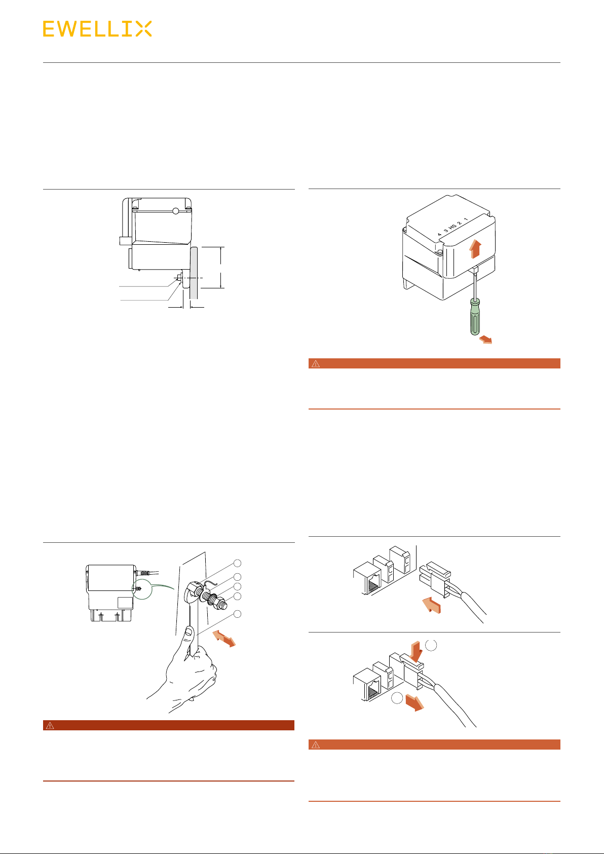
4.2.3 Removing the control unit........................................7
4.2.4 Fastening the control unit externally .......................8
4.2.5 Installing / uninstalling the earth cable (option).......8
4.3 Startup.............................................................................8
4.3.1 Opening the control box cover ................................8
4.3.2 Connecting / disconnecting the actuator cable on
the control unit....................................................................8
4.3.3 Connecting / disconnecting the control device ......9
4.3.4 Closing the control box cover..................................9
5.0 Operation..................................................................... 10
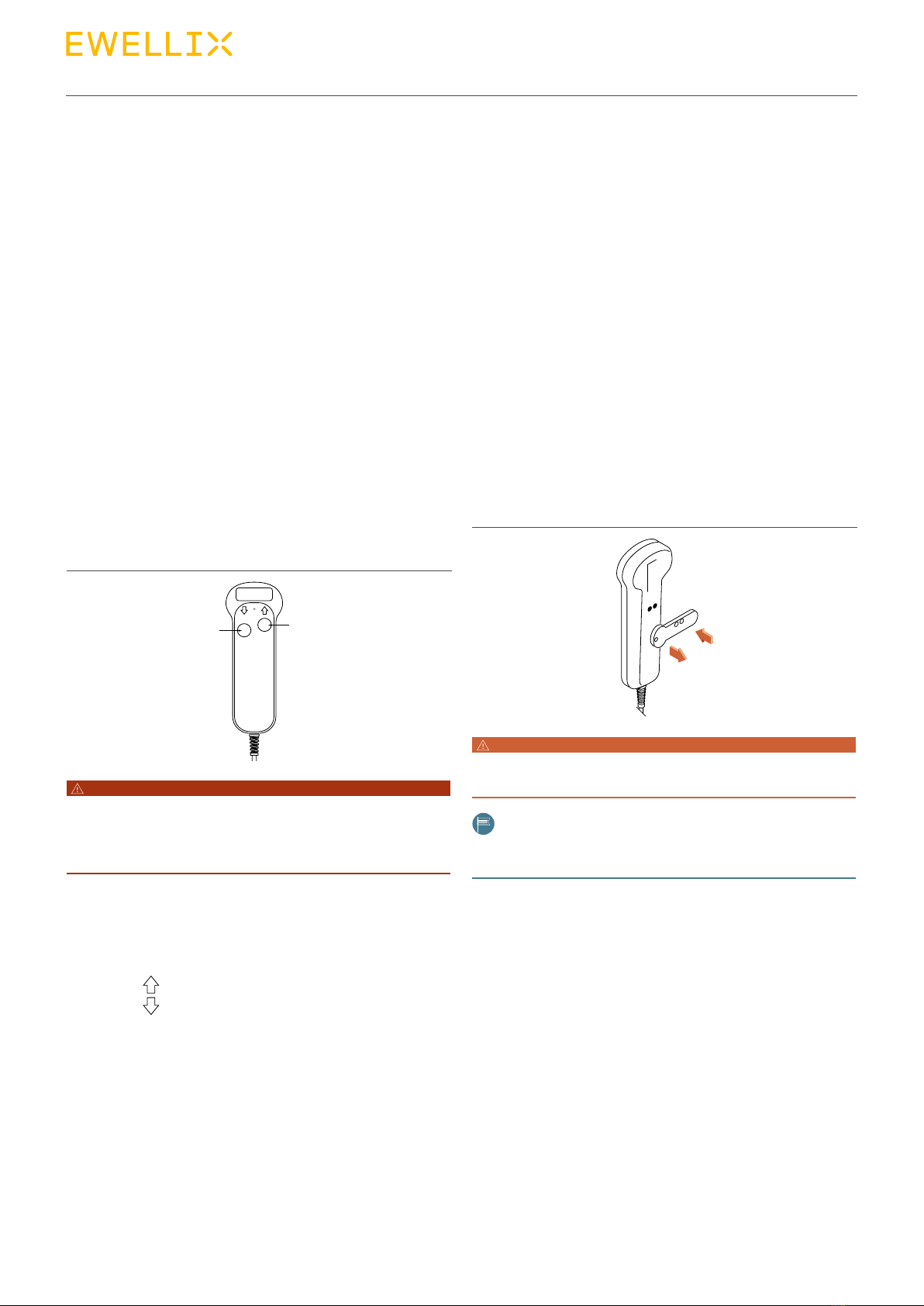
5.1 Controlling an actuator.................................................. 10
5.1.1 Fastenin g hook....................................................... 10
5.2 Locking device .............................................................. 10
5.2.1 Locking the handswitch......................................... 10
5.2.2 Unlocking the handswitch ..................................... 10
5.3 "Emergency lowering" in the event of a power failure
(option) ................................................................................. 11
5.3.1 Changing the batteries .......................................... 11
5.4 Rapid adjustment (optional).......................................... 11
5.4.1 Function ................................................................. 11
5.4.2 Usage ..................................................................... 12
6.0 Maintenance and Care............................................... 13
6.1 5.1 Mainte na nce ............................................................ 13
6.1.1 Dut y cyc le .............................................................. 13
6.1.2 Thermofuse ............................................................ 13
6.2 Care............................................................................... 13
6.2.1 Protection from water, cleaning, disinfecting........ 13
6.3 Disposal ........................................................................ 13
6.4 Liability .......................................................................... 14
6.5 Troubleshooting ............................................................ 15
7.0 Appendix ......................................................................16
WAINTING
Read this manual before installing, operating or maintaining this
actuator. Failure to follow safety precautions and instructions
could cause actuator failure and result in serious injury, death or
property damage.

4
Ecomag
1.0 Important safety information
The actuator is assembled and delivered by Ewellix accord-
ing to the ordering key. Modication of the actuator is not al-
lowed in any way. Any modication will void the warranty
and could create a safety hazard. Ewellix disclaims any and
all liability or responsibility for the modied product and for
any claims, demands or causes of action for damage or for
personal injury resulting from modication and/or use of
such product. In addition, if the actuator has been disas-
sembled, misused or altered without prior written authorisa-
tion, warranty will be voided. These installation instructions
are part of the actuator and should be kept together with all
relevant documentation regarding the application in which it
is used.
The following are important safety precautions that must be
followed during installation:
• All electrical installation and maintenance should be car-
ried out by qualied personnel.
• Terminate power supply to the actuator before installation
or maintenance.
• Make sure that the actuator is not under load or in tension
before installation or maintenance.
• Use the appropriate safety equipment when installing/re-
pairing the actuator.
• When connecting the actuator, make sure that the power
supply corresponds to what is required in the technical
specications. See section 5 below.
• When heavy load and high duty factor is used, motor and
surrounding components can get hot.
DANGER
Indicates a dangerous situation, which
will lead to death or serious personal
injury, if the precautionary measures are
ignored.
WARNING
Indicates a dangerous situation, which
can lead to minor or moderate injury or
property damage, if the precautionary
measures are ignored.
CAUTION
Indicates a dangerous situation, which
can lead to minor or moderate injury
the precautionary measures are ignored.
NOTICE
Indicates information considered
important, but not hazard-related (e.g.
messages relating to property damage).
NOTE
Emphasizes useful hints and
recommendations as well as information
for ecient and trouble-free operation.

5
2.0 General
5
2.0 General
2.1 Using the Technical
Instructions
The Technical Instructions are intended for designers or
specialists who use the ECOMAG linear actuator in their
products, and for tters who work with the actuator. The
Technical Instructions contain all relevant information on this
Ewellix product.
We reserve the right to make changes which are in the inter-
est of technical progress.
Please read the Technical Instructions carefully and, above
all, pay careful attention to the Safety Instructions.
The Technical Instructions should be used for drawing up
the User Manual for the end product.
2.2 Correct usage
The ECOMAG linear actuator has been designed for use in
conjunction with the following Ewellix components:
• SEM 1 control unit and
• EHE handswitch
and is specically intended for adjusting chairs and couches
in medical and care sectors.
Other uses must be discussed with Ewellix Liestal.
2.3 Ambient conditions
Operation:
Temperature 10 °C to 40 °C
Humidity max. 85%
WAINTING
This actuator must not be operated in potentially explosive
atmospheres.
Storage / transport:
Temperature -20 °C to 60 °C
Humidity max. 95%
The unit is only suitable for indoor use and must not be sub-
jected to the elements.

6
Ecomag
6
3.0 Function
ECOMAG linear actuators are DC actuators with worm gears
and spindle units. The gears convert the motor's rotational
movement into a linear movement through the threaded
spindle's rotation being transferred to a pushing tube via a
special nut.
The stroke is limited by built-in limit switches.
The power is supplied via an attachable or externally tted
SEM 1 control unit. The control unit consists of a control box
housing the transformer, the converter, up to 4 motor socket
connections and a socket connection for the control device
(e.g. handswitch).
WAINTING
The maximum load specied on the label must not be exceeded,
since doing so will mean that the prescribed level of safety will
not be provided.
The actuator may be destroyed if it is overloaded!
The linear actuator is operated using a control device (e.g.
an EHE handswitch).
The feed speed is a function of the load!
The ECOMAG can be loaded with push forces (ECO 2/4/6/8)
or pull and push forces (ECO 3/5/7/9).
DANGER
The ECOMAG linear actuator "push version" (ECO 2/4/6/8)
may only be subjected to compressive loads. If pull forces are
applied, the push tube can disengage from the outer tube.
Risk of accident!
The maximum load on the actuator shown on the label refers
to the centric push tube axis.
A mechanical anti-pinching device for pull forces is tted in
the "push" versions. In the "pull-push" versions, a mechani-
cal anti-pinching device is available as an option.
The self locking of the actuator is at least equal to the push-/
pullforce.

77
4.0 Installation and startup
4.1 Scope of delivery
The ECOMAG actuator system comprises the following:
• Control unit
• Actuator and
• Control device
4.2 Installation
The linear actuator must only be installed over the two fork
heads. The load must act centrally on the push tube axis
and, when the actuator is installed, it must be free from any
other mechanical forces.
DANGER
The bolts and brackets for transferring the forces must be
suitable for the purpose intended and be matched to the
dimensions of the fastening ttings.
Risk of accident!
If there is a risk of hitting a mechanical limit stop during a
stroke movement, Ewellix recommends that mechanical an-
ti-pinching protection or a current cuto device be used.
When the rapid adjustment option is used, it must be en-
sured that the entire stroke movement can be completed.
4.2.1 Mounting position
As a general rule, all mounting positions are possible, pro-
vided the following points are noted:
If the control unit is plugged in, only the mounting positions
shown in Fig. 1 from 0° to 90° are permitted.
If an overhang arrangement is used, the control unit must
also be xed in position with cable ties. The control unit can
otherwise work itself loose.
90° 90°
270° 270°
Fig. 1
4.2.2 Mounting the control unit on the
actuator (ECO 2/3/6/7 only)
Slide the control unit onto the actuator as shown in g. 2.
The control unit locks into position with an audible click of
the locking mechanism.
Fig. 2
4.2.3 Removing the control unit
Gently lift the nose with a screwdriver, and at the same time
push the control box in the direction of the arrow (⮑Fig. 3).
Fig. 3

8
Ecomag
4.2.4 Fastening the control unit
externally
The control unit must be installed at the installation slots
provided (⮑Fig. 4), and must be installed so that it is free
from mechanical forces and vibrations.
Tightening torque: 1.7 – 2 Nm
M5
Mt: 1,7 - 2 Nm
min. 65
Ø 5,3/15×0,8
13
Fig. 4
4.2.5 Installing / uninstalling the earth
cable (option)
• Undo the nut (4) and contact washer (3) from the ground-
ing bolt (1). (⮑ g. 5)
• Push the cable lug for M4 (2) of the device you wish to
earth over the grounding bolt (1).
• Fasten the grounding bolt (1) onto the hexagon using the
wrench (5).
• Screw the contact washer (3) and nut (4) onto the thread of
the grounding bolt (1).
• Tighten with the torque wrench to 1.5 Nm – 1.8 Nm.
The cable is uninstalled in the reverse order.
1
2
3
4
5
Fig. 5
DANGER
To ensure that the grounding bolt (1) does not rotate too, it must
be fixed in position using a wrench (5) when the device's earth
connection is being tightened or unscrewed.
Risk of accident!
4.3 Startup
4.3.1 Opening the control box cover
Gently lift the nose with a screwdriver, and at the same time
push the control box cover in the direction of the arrow
(⮑Fig. 6).
Fig. 6
WARNING
All cables must be secured so that no forces act on the control unit
connections. Incorrectly connected cables may become loose and
damage the control unit!
4.3.2 Connecting / disconnecting the
actuator cable on the control unit
• Connect the actuator cable in the direction of the arrow
(⮑Fig. 7). Note: Observe the plug number.
• Disconnect the actuator cable in the direction of the arrow
(⮑Fig. 8).
Fig. 7
1
2
Fig. 8
WARNING
Motor connections that are not occupied on the control unit are
sealed at the factory. The seals must not be removed.
If liquid is allowed to penetrate the seals, the control unit will be
damaged!

9
4.0 Installation and startup
4.3.3 Connecting / disconnecting the
control device
• Connect the control device plug (e.g. handswitch) in the di-
rection of the arrow (⮑ g. 9). Note: Observe the plug
type.
• Disconnect the plug in the direction of the arrow
(⮑Fig. 10).
Fig. 9
1
2
Fig. 10
WARNING
You should ensure that the handswitch cable plug is inserted
correctly.
If the front film is damaged (i.e. allowing liquid to penetrate), the
handswitch must be replaced. The handswitch would be damaged
if liquid were allowed to penetrate it!
4.3.4 Closing the control box cover
• Move the control box cover in the direction of the arrow
(⮑Fig. 11).
• The control box cover is only closed once an audible click
of the locking mechanism is heard.
Fig. 11
WARNING
Protection class IPX4 is only guaranteed if the control box cover is
closed with an audible click of the locking mechanism, and the seal
edges and nose are not damaged

10
Ecomag
5.0 Operation
5.1 Controlling an actuator
The EHE handswitch is used to actuate one or more
ECOMAG linear actuators. A control panel is provided on
the front foil of each handswitch for each actuator that is to
be controlled (⮑ g. 12). This consists of two push-buttons
that are positioned oset from each other. On the front plate
are the symbols which are assigned to the function and are
used for adjusting the individual linear actuators.
Up to 4 linear actuators can be actuated separately.
AB
AUF
Fig. 12
DANGER
If the feed speed of the linear actuator diminishes, or it no longer
works under load, it must be uninstalled immediately and taken out
of use.
Risk of personal injury!
Pressing one of the push-buttons activates the relevant lin-
ear actuator. It moves for as long as the button is held
depressed.
• Button The actuator extends
• Button The actuator retracts
5.1.1 Fastening hook
It is possible to retrot the handswitch with a fastening hook.
The fastening hook is attached to the adhesive surface pro-
vided on the rear of the handswitch using adhesive lm.
5.2 Locking device
As an option, it is also possible to lock the individual actua-
tors on the EHE handswitch. This gives the unit failure safety
in accordance with EN 60601-2-38.
In Lock or Unlock programming mode, the locking key must
always be placed in the bores situated on the rear of the
handswitch.
Fig. 13
WARNING
To avoid inadvertent activation of the control device, we
recommend the optional locking device (EHE3).
Note
After locking or unlocking, the locking key must be removed and
the set functions checked.
5.2.1 Locking the handswitch
Place the locking key with cam into the bore on the rear of
the handswitch.
Press the "DOWN" button of the actuator that is to be
locked. The display lights up yellow. The actuator is locked.
5.2.2 Unlocking the handswitch
Place the locking key with cam into the bore on the rear of
the handswitch.
Press the "UP" button of the locked actuator. The display
lights up green. The actuator is unlocked.

11
5.0 Operation
5.3 "Emergency lowering"
in the event of a power
failure (option)
If the power fails, the actuators can be moved to their lower
terminal position.
If the "EMERGENCY lowering" features a patient safety
function in the event of a power failure, the user must ensure
that:
• the battery capacity is satisfactory,
• the function is checked regularly by briey pressing the
"AB" ("DOWN") button.
The following batteries, which have been approved by the
manufacturer, may be used:
• Panasonic 9 V Alkaline 6LR61,
• Varta 9 V Alkaline 6LR61 and
• Energizer 9 V Alkaline 6LR61
5.3.1 Changing the batteries
• Remove the cover (⮑Fig. 14).
• Replace the batteries.
• Replace the cover with the line mark facing upwards.
Fig. 14
WARNING
Ewellix, recommends that the batteries be replaced each time the
"EMERGENCY lowering" function is used.
Damaged, spent batteries must be replaced anyway.
WARNING
Batteries must be disposed of correctly or returned to Ewellix. They
must not be disposed of in the general household waste!
WARNING
Protection class IPX4 is only guaranteed if the marking on the cover
matches the marking on the housing.
5.4 Rapid adjustment
(optional)
5.4.1 Function
The rapid adjustment function is used for "emergency rapid
lowering" of the head or the foot of the bed (during patient
resuscitation).
If a power failure or actuator malfunction should occur, or for
beds which are not connected to a power supply, the rapid
adjustment device can be used to manually lower the head
or foot of the bed (further option).
When installing an actuator with rapid adjustment function, a
warning notice (⮑ Fig. 15) in accordance with EN 60601-1,
Section 6.3c and 6.4, must be attached clearly to the end
product (insofar as the end application is subject to this
standard).
Fig. 15
WARNING
The rapid adjustment function should only be used in emergencies,
or to test that it is working properly.
When retracted, the actuator must lie against a fixed limit stop (e.g.
bed frame), since otherwise the actuator may be damaged by a
rapid- lowering action.
No transverse forces (misaligned mounting) must be allowed to
act on the linear actuator, since otherwise the function of the rapid
adjustment feature cannot be guaranteed.
The screws in the pivot clamp must not be tightened or loosened!
WARNING
The rapid adjustment function must be checked every 6 months.

12
Ecomag
5.4.2 Usage
• Open the red clamping lever (⮑Fig. 16, (1)).
While doing so, hold the head of the bed rmly. Depending
on the bed design, the head or foot can lower quickly.
Fig. 16
• Manually press the rapid adjustment mechanism down-
wards (⮑Fig. 17, (3) e.g. backrest).
Fig. 17
• Close the red clamping lever (⮑Fig. 18, (1)) until it
reaches its end position (4).
Fig. 18
You must ensure that, whatever position the clamping lever
is in, it can be actuated as shown in gs. 14 and 15.
After a rapid lowering action, the clamping lever must be in
closed position before the linear actuator is used again.

13
6.0 Maintenance and Care
6.1 5.1 Maintenance
The actuators may only be opened and worked on by the
Ewellix Customer Service.
The fork heads, housing and power cable must be checked
for mechanical damage (e.g. cracks) every 6 months.
DANGER
The maximum current consumption under full load must be
measured. It must not exceed the value specified on the label.
Higher current consumption means that the linear actuator is
overloaded and may be damaged!
The user must undertake to monitor the products vigilantly.
The actuators are greased with Ewellix-approved lubricants,
and do not require any maintenance for the following service
life:
Service life: Max. 10 000 double-strokes with a stroke of 200 mm.
(The question of how the double-stroke specication is
translated into a useful service life must be dened by the
manufacturer of the end product).
When the service life expires, the actuator must be removed
and overhauled by the manufacturer. Risk of personal injury!
For applications where it is highly likely that the service life
will be exceeded, we recommend the use of the optional
safety nut.
The rapid adjustment option must be checked every 6
months. If excessive force is needed to move the actuator,
or it runs too freely, it should be exchanged.
6.1.1 Duty cycle
The actuator has been designed for intermittent operation
(see label). If a higher duty cycle is used, please contact the
Ewellix factory.
6.1.2 Thermofuse
The ECOMAG linear actuator is tted with a thermofuse. The
thermoswitch integrated into the motor switches the actua-
tor o if the temperature becomes excessive.
6.2 Care
6.2.1 Protection from water, cleaning,
disinfecting
The following protection classes are only guaranteed in as-
sembled status:
• Linear actuator and control unit IP X4
• Housing of the optional mains
disconnection device IP X0
• Handswitch IP X6 and IP X7
Clean after use in order to avoid the accretion of residues!
The actuator may be cleaned with a damp cloth and water.
Add a little isopropyl alcohol if necessary
WARNING
Ensure that no liquids are allowed to penetrate the connections!
WARNING
Washing water with chemical additives must be pH neutral.
Excessively acidic or alkaline washing water can permanently
damage the metal and plastic components of the actuator.
High-pressure steam cleansing equipment must not be used.
6.3 Disposal
The actuators and control unit components may be returned
to Ewellix for disposal.

14
Ecomag
6.4 Liability
In every case, the owner or operator of the unit shall be lia-
ble for its function if it has been incorrectly maintained or re-
paired by persons who are not employed by the Ewellix
Service Department or if the unit has not been operated in
accordance with the specied application.
Ewellix shall not be liable for any damage resulting from fail-
ure to observe these instructions. These instructions shall
not be regarded as an extension of the warranty and liability
terms set out in the Conditions of Sale and Supply applied
by Ewellix.
The product is not subject to the labelling requirements of
the CE or EMC guidelines.
The required EMC measures for the end product must be
met by its manufacturer, taking into account installation fac-
tors, wiring and control, and these must be checked for
compliance with the intended application.
Observance of these instructions is the responsibility of the
manufacturer of the machine or equipment.

15
6.0 Maintenance and Care
6.5 Troubleshooting
DANGER
Before performing any adjustments to the mechanisms, the power
supply to the actuators must be disconnected.
Risk of electric shock!
Fault Cause Remedy
Actuator(s) not working Control unit not plugged in Plug in the mains cable.
Poor connector contact Plug in the power, control device or motor plug correctly
Actuator faulty Return the actuator to the Ewellix Service Department
Control device faulty Replace the control device
Control unit faulty Replace the control unit
Actuator overheated Wait 20 minutes
Actuator not plugged in Plug in the motor cable
Markedly reduced speed Motor, gears or nuts faulty Return the actuator immediately to the Ewellix Service
Department
Very loud running noise Motor, gears or nuts faulty Return the actuator immediately to the Ewellix Service
Department
Actuator only runs in one direction Cut-o faulty Return the actuator to the Ewellix Service Department
Control device faulty Replace the control device
Control unit faulty Replace the control unit
Control unit not working Control unit not plugged in Plug the mains cable in
Control unit faulty Return the control unit to the Ewellix Service Department
Mains cable faulty Return the control unit to the Ewellix Service Department
Control device faulty Replace the control device
Poor connector contact Fit the plug correctly.
Control device not working Poor connector contact Fit the plug correctly
If you are unable to eliminate a fault, contact the Ewellix
Service Department.
4.0 Installation and startup

16
Ecomag
7.0 Appendix
Technical data
Please refer to the following document:
Ecomag datasheet
PUB IL-07004-EN-October 2019
For further technical information please contact Ewellix

17
Appendix
Technical data
Ecomag
Linear actuator
Benets
• Compact
• Cost eective
• Silent operation
• Control unit can be mounted to the
actuator
Unit ECO 20/40 ECO 60/80 ECO 30/50 ECO 70/90
Rated push load N 2 000 6 000 2 000 6 000
Rated pull load N 0 0 2 000 4 000
Speed (full load to no load) mm/s 9 to 13 4 to 7 9 to 13 4 to 7
Stroke mm 50 to 300 50 to 300 50 to 300 50 to 300
Retracted length mm S+160 S+16 0 S+16 0 S+16 0
Voltage V DC 24 24 24 24
Power consumption W70 120 70 120
Current consumption A4646
Duty cycle %10 (1/9) 10 (1/9) 10 (1/9) 10 (1/9)
Ambient temperature °C +10 to +40 +10 to +40 +10 to +40 +10 to +40
Type of protection IP ×4S ×4S ×4S ×4S
Weight kg 2,1 2,1 2,5 2,5
Color – Black or grey Black or grey Black or grey Black or grey

18
Ecomag
Dimensional drawing
Connecting diagrams
Legend:
S = stroke
L = retracted length
Suitable control units and accessories
Black
Jack Plug V DC
Limit switches
Actuator
Red
+
-
M
15
17
L = S+160
165
72
113
15
15 26
26
6+0,7
+0,5
6+0,7
+0,5
Ø30
Ø30
140
A
25
25 22,4
15
15
15
Ø30 17
83,4
79
Label
position
Label
position
72
L = S+160
6+0,7
+0,5
6+0,7
+0,5
Ø30
15 15
30
32
30
Ø25 10 +0,3
+0,15
10+0,3
+0,15
45° 0°
90°
135°
45° 0°
90°
135°
Ecomag 2-3-6-7
Ecomag 4 -5-8-9
Rear attachment positionFront attachment
push and pull version
Rear attachment
push and pull version
Push version only Push and pull version
Control units
SCU
VCU
BCU
MCU
SEM
ECOMAG ●●●●●
Operating switches
EHA 1 ●
EHA 3 ●●●
EHE ●
STJ ●●●
STF ●
STA ●
STE ●●●
Desk switchHand switch Foot switch

19
Appendix
Safety factor load conditions
0
1 500
4 500
3 000
6 000
0 100 200 300
400
Stroke length [mm]
Push load [N]
Push load reduction safety factor = 4
Performance diagrams
0
10
8
6
2
4
14
12
16
02 000 4 000 6 000 8 000
Speed [mm/s]
Load [N]
Current consumption [A]
Load [N]
ECO 20 / 30 / 40 / 50 ECO 60 / 70 / 80 / 90
0
10
8
6
2
4
14
12
16
02 000 4 000 6 000 8 000
Speed-load diagram Current-load diagram

20
Ecomag
Type
Load /Housing
Push Pull Housing
2 000 N 0 N Large 2
2 000 N 2 000 N Large 3
2 000 N 0 N Small 4
2 000 N 2 000 N Small 5
6 000 N 0 N Large 6
6 000 N 4 000 N Large 7
6 000 N 0 N Small 8
6 000 N 4 000 N Small 9
Encoder
No encoder, coiled cable, 2-pin Minit plug or customization 0
No encoder, coiled cable, DIN8 plug or customization 9
2-Hall encoder, 8 pulses, straight cable, DIN8 plug (small housing only) F
Current cut-o
No 0
Yes (not available for ECO4.-/ECO5.-/ECO8.-/ECO9.-) 1
Stroke (S)
50 mm 05
100 mm 10
150 mm 15
200 mm 20
250 mm 25
300 mm 30
Other stroke lengths; 50<S<300 mm 00
Front attachment (groove depth 17 mm)
Hole, Ø = 12 mm, groove width 10 mm M
Customized X
Rear attachment (groove depth 15 mm)
Hole, Ø = 12 mm, groove width 10 mm M
Customized X
Orientation of rear attachment
0° 1
45° 3
90° 5
135° 7
Color
Black A
Grey B
Option
No option 0
Back-up nut (available only for drives with 6 kN, mandatory for IEC 60601-1) – only for ECO 7/9, L = +23 mm A
Customization
Ordering key
Options shown in yellow are only available on request. Contact Ewellix for more information on minimum quantities and additional costs.
E C O -
This manual suits for next models
3
Table of contents
Other Ewellix Controllers manuals