manuals.online logo
Brands
  1. Home
  2. •
  3. Brands
  4. •
  5. EWELLY
  6. •
  7. Thermostat
  8. •
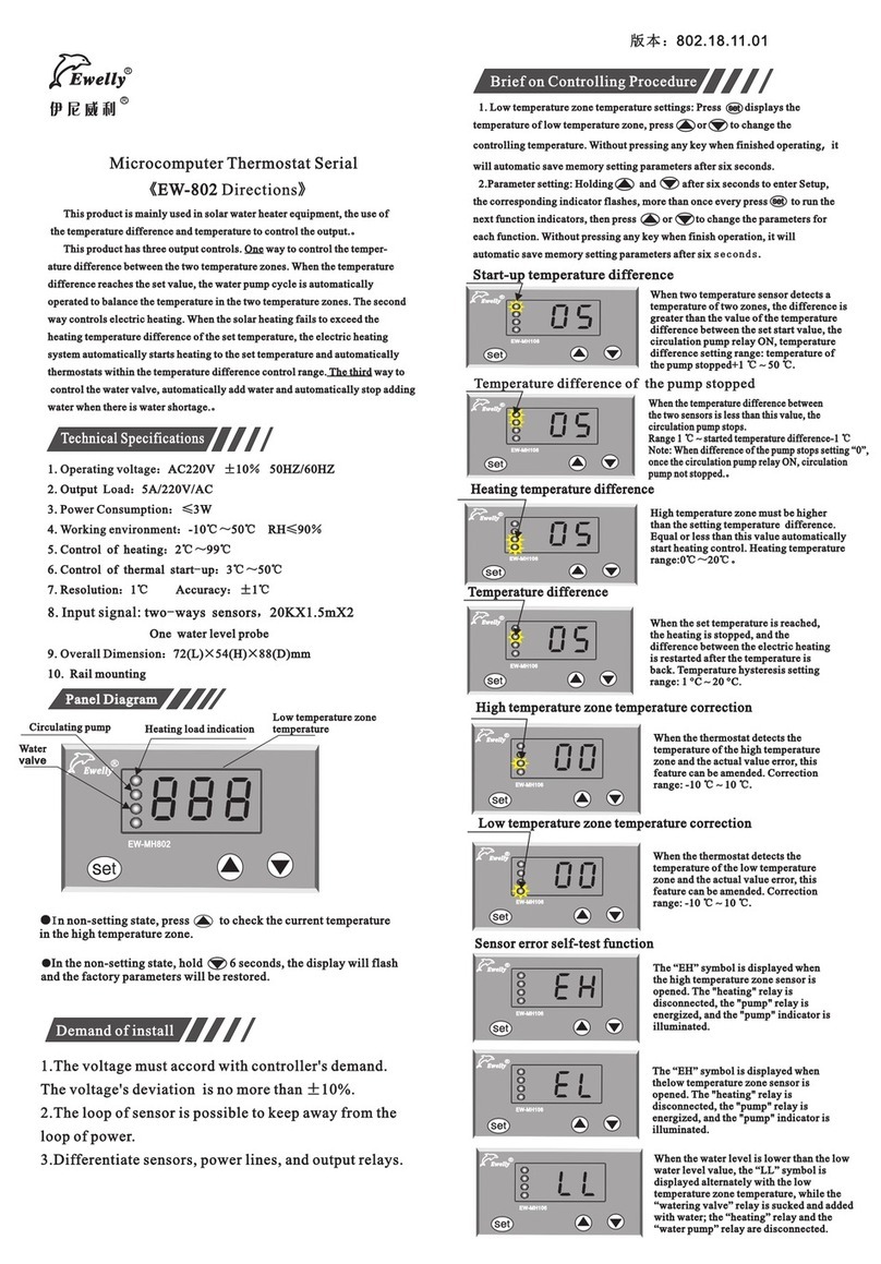
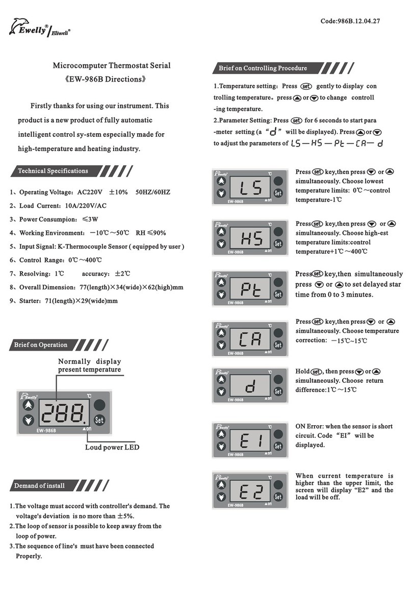
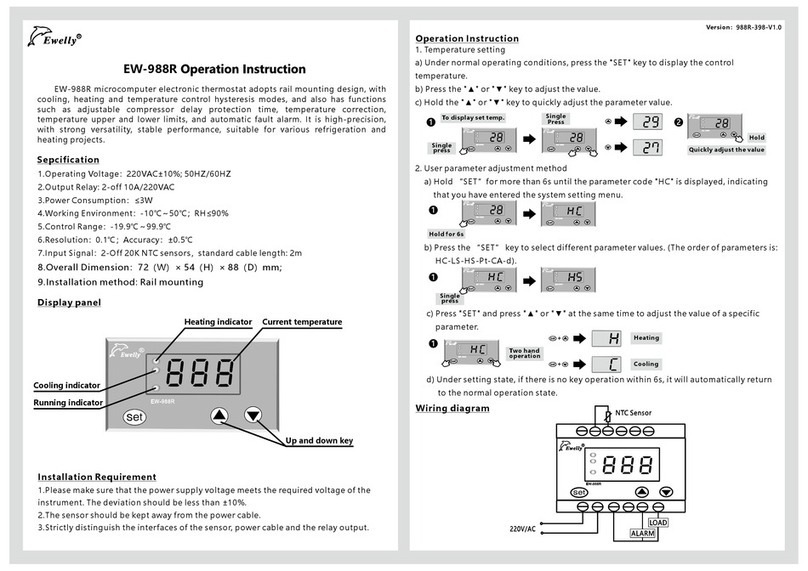
  9. EWELLY EW-T205L User manual

EWELLY EW-T205L User manual

Version:T205L.19.05.04
F
c
EW-T2 0 5 L 现时温度 设定温度
se t t em p
tem per atu re
SE T
SE T
SE T
SE T
SE T
EW-T205L
SET
现时温度 设 定 温度
set t e mp
temperature
EW-T 20 5L
SET
现时温度 设 定 温度
set temp
tempe r ature
F
c
EW-T20 5L
SET
现时温度 设 定 温度
set t e mp
temperature
F
c
EW-T20 5L
SET
现时温度 设 定 温度
set temp
temperature
EW-T20 5L
SET
现时温度 设 定 温度
set t e mp
temperature
EW-T20 5L
SET
现时温度 设 定 温度
set temp
temperature
F
c
EW-T20 5L
SET
现时温度 设 定 温度
set t e mp
temperature
F
c
EW-T20 5L
SET
现时温度 设 定 温度
set temp
tempe r ature
EW-T20 5L
SET
现时温度 设 定 温度
set t e mp
temperature
EW-T20 5L
SET
现时温度 设 定 温度
set temp
temperature
F
c
EW-T20 5L
SET
现时温度 设 定 温度
set t e mp
temperature
F
c
EW-T20 5L
SET
现时温度 设 定 温度
set temp
tempe r ature
F
c
EW-T20 5L
SET
现时温度 设 定 温度
set t e mp
temperature
F
c
EW-T20 5L
SET
现时温度 设 定 温度
set temp
tempe r ature
EW-T20 5L
SET
现时温度 设 定 温度
set t e mp
temperature
EW-T20 5L
SET
现时温度 设 定 温度
set temp
tempe r ature
EW-T20 5L
SET
现时温度 设 定 温度
set t e mp
temperature
EW-T20 5L
SET
现时温度 设 定 温度
set temp
tempe r ature
EW-T20 5L
SET
现时温度 设 定 温度
set t e mp
temperature
EW-T20 5L
SET
现时温度 设 定 温度
set temp
tempe r ature
F
c
EW-T20 5L
SET
现时温度 设 定 温度
set t e mp
temperature
F
c
EW-T20 5L
SET
现时温度 设 定 温度
set temp
tempe r ature
EW-T20 5L
SET
现时温度 设 定 温度
set t e mp
temperature
EW-T20 5L
SET
现时温度 设 定 温度
set temp
temperature
EW-T20 5L
SET
现时温度 设 定 温度
set t e mp
temperature
EW-T20 5L
SET
现时温度 设 定 温度
set temp
tempe r ature
EW-T20 5L
SET
现时温度 设 定 温度
set t e mp
temperature
EW-T20 5L
SET
现时温度 设 定 温度
set temp
tempe r ature
EW-T20 5L
SET
现时温度 设 定 温度
set t e mp
temperature
EW-T20 5L
SET
现时温度 设 定 温度
set temp
tempe r ature
F
c
EW-T20 5L
SET
现时温度 设 定 温度
set t e mp
temperature
F
c
EW-T20 5L
SET
现时温度 设 定 温度
set temp
temperature
EW-T20 5L
SET
现时温度 设 定 温度
set t e mp
temperature
EW-T20 5L
SET
现时温度 设 定 温度
set t e m p
temperature
EW-T20 5L
SET
现时温度 设 定 温度
set t e mp
temperature
EW-T20 5L
SET
现时温度 设 定 温度
set temp
tempe r ature
EW-T20 5L
SET
现时温度 设 定 温度
set t e mp
temperature
EW-T20 5L
SET
现时温度 设 定 温度
set temp
tempe r ature
SE T
temperature
Welcome to choose our instruments. This micro-
computer temperature controller is specialized
designed for refrigerator and freezer, easy-to-use,
accurate control, and strong anti-interference. Our
sensor is precisely made and sealed. It is moisture
proof, therefore its performances are more stable and
reliable.
1 : AC220V ±10% 50HZ/60HZ
2 : Compressor relay 30A/220V/AC, can be
used directly in loads lower than 30A, others are 5A/220V/AC
(4-OFF).
3:≤3W
4 : -10℃~50℃ R H≤90%
5:—45℃~45℃ (- 40℉~120℉)
6:>-20℃ is 0.1℃/1℉
≤-20℃ is 1℃/1℉
: >- ℃ is ±0.5℃/℉
≤-20℃ is 1℃/1℉
8. Input: 1-OFF temp. sensor; 1-OFF defrost sensor
: × ×
×
. Operating voltage
. Output Load
. Power Consumption
. Working environment
. Control Range
. Resolving
7. Accuracy 20
9. Overall Dimension 160mm(length) 45mm(width)
81mm(high)
10. Hole Size: 138mm(length) 32mm(width)
Microcomputer Thermostat Serial
-EW-T205L Operation Manual
Technical Specifications:
Appearance Panel
1. Temp. control setting: Press to display the set temp., press
or to change set temperature. Set temp.≤-20℃ is 1℃, Set
temp.>- 20℃ is 0.5℃.
2. Parameters setting: Hold key for 6s to enter the manual, it
display , then press
If the password is incorrect, it display and the password is
hidden, parameters are read only and cannot be changed.
3. To display temp. of defrost sensor: Press under unsetting mode.
It displays temp. of defrost sensor and does not display current temp.
4. Press and hold for 5s, it displays the defrost mode or defrost
termination remaining time.
5. Press and hold to force to defrost.
6. Press for 6s, the display will flash, and all parameters are
restored to factory default values. Restart the instrument after
parameters are reset.
7. Press , the lighting relay closes and indicator turns on, then
press again, the lighting relay is off and the indicator turns off.
8. Press for 3s to power off the thermostat, then press again
for 3s to turn on the thermostat.
or to enter menu password, after
entering password, press to enter menu setting, it displays ,
then press continuously to display following parameter codes in
sequence:
Operation Instructions
Display Instruction:
Password setting, press for 6s, it displays PA and
figures 00 , then press or to set password,
then press again, it displays LS.
When it displays LS , press or to modify temp.
from -50℃/-40℉~set temp. -1 ℃/℉.
Press again, it displays HS, then use or to
modify high temp. limit, from set temp.~ 50℃/140
℉.
Press again, it displays d, then use or to
modify return temp. difference, setting range is
1~ 10℃/36℉.
Press again, it displays Pt, then use or to
modify compressor start time delay, setting range is
0~10min.
Press again, it displays CA, then use or to
modify room temp. calibration, setting range is -15
~15℃/-60~60℉.
Press again, it displays Cb, then use or to
modify defrost sensor temp. calibration, setting
range is -15~15℃/-60~60℉.
Press again, it displays F0, then use or to
modify defrost type, 00 is electrical defrost and 01
is hot gas defrost.
Press again, it displays F1, then use or to
modify defrost time, the setting range is 1~60min.
Press again, it displays F2, then use or to
modify defrost cycle, the setting range is 0~99hrs.
Press again, it displays F3, then use or to
modify defrost termination temp., the setting range
is 0~35℃/30~110℉.
Press again, it displays F4, then use or to
select fan running mode, 0 is fan runs or stops synch-
ronically and 1 is normally open.
Press again, it displays F5, then use or to
modify dripping time after defrost, the setting range
is 0~20mins.
Press again, it displays F6, then use or to
select fan re-start mode after defrost, “F7” represe-
nts time, and “F8” represents temperature.
Press again, it displays F7, then use or to
modify fan start delay time after defrost, the setting
range is 0~20mins.
Press again, it displays F8, then use or to
modify fan start temp. after defrost, the setting
range is -20~20℃/-4~68℉.
Press again, it displays CF, then use or to
select the unit of temperature, ℃/℉.
Press again, it displays CPR, then use or
to change password (default 00~99).
Press again, it displays bF, then use or to
set buzzer, 00 is alarm without sound, 01 is alarm
with sound.
SE T
SE T
SE T
SE T
SE T
SE T
SE T
SE T
SE T
SE T
SE T
SE T
SE T
SE T
SE T
SE T
SE T
SE T
SE T
SE T
Room Tmep.
calibration 00
℃/°
F
Wiring Diagram
Program Parameter Table
Code Function Setting range
Factory Settings
Unit
-45℃
45℃
-15~15℃/-60~60
0~10
-30℃/5°
20℃/60°
00
1
2℃/5°
℃/°
min
01~60 10
00~99 Hr
6
00~35
05/40
00
00=synchronous operation
01=operation all the time
02
00~99 00
-
/-40°
FF
F
120°
F
F
℃/°
F
℃/°
F
℃/°
F
to control temperature -1℃
control temperature+1 ℃ to
35~110
0
00= electic heating defrosting
01= hot-gas defrosting
-
-
1-10℃
1-36°
F
℃/°
F
Password input
Temp. set
lower limit
Temperature return
difference
Time delay
Defrosting type
Defrosting time
Defrosting cycle
Defrost termination
temperature
Fan start mode
Dripping time after
defrost
F
Temp. set
upper limit
-15~15/- 60~60
Defrost calibration
min
00~10 min
00
Fan running mode
after defrost
00= run as per F7 setting
01= run as per F8 setting
-
02
Fan start delay time
after defrost 00~20 min
Fan start temp. after defrost
(defrost temp. ≤ set temp.)
-20~20℃
-04~68℉
-08℃/18℉
℃/°
F
00
-
00
-
C-℃;F-℉
Temperature unit
transfer C
℃/°
F
Password setting
Buzzer setting
00~99
00~01
Notes: If a password is set, the locking indicator turns on, and only
the right (PA) can change other parameters, otherwise the set para-
meters can only be read and cannot be modified, in addition, the p-
assword menu is hidden, but the control temp. still can be modified.
- When F7 is set to “00”, F7 is enable, and F8 is disable;
When F7 is set to “01”, F8 is enable, and F7 is disable.
- When transfer the temp. unit, temp. units (℃/℉) are restored
to the factory set parameters.
- When defrost cycle is set to “0”, defrost function turns off.
Feature Descriptions
Cooling:
When the current temperature ≥ set temperature + temp. return difference and reach
set“time delay”, the load relay is closed.
Stop cooling:
When the current temperature ≤ setting temperature, the load relay is off.
Enter defrost mode:
1. When the instrument finishes running a set “running cycle” after defrost or just
after boot, it enters defrost mode (the load relay is off , defrost relay on , defrost in-
dicator is on), and the set temp. displays the defrost temp. (Need to press after
existing defrost mode to check).
Note: Under defrost mode, room temp. sensor is displayed on left hand side, defrost
sensor temp. is displayed on right hand side.
Exit defrost mode:
1. Under the defrost mode, when the system runs over the set defrost time, defrost relay
off, defrost indicator off, system exits defrost mode and returns to the normal control.
2. The defrost sensor reaches defrost status, the system returns to the normal control.
Note: When pressing, if defrost sensor temp. ≥ defrost termination temp., the system
will not enter defrost status, and will remain current operation mode.
Failure mode management:
1. Note: the super temperature processing mode is as follows
1. No warning while defrosting;
2.When temperature exceeds set value +10 ℃/30℉, there will be a HH alarm output, it
enters the fault runningg mode, the compressor runs for 45 minutes and stops for 15
minutes;
3. When the temperature is lower than set value -5℃ /15℉, there will be a LL output
alarm, all operations will be stopped;
4. When sensor is open or short circuit, there will be an E1 alarm output, and it enters
the fault running mode.
Troubleshooting
Failure
No display when power is on
With display but no operation
Displayed temperature unstable
or malfunction
Real temp. is much different to
thermostat display.
Not shut down after temperature
reached
LL shown
HH shown
Causes Solutions
Whether the power source is off;
Whether the temperature controller is
defective.
Set temperature higher than the current
temperature; pressure overrun and overloaded,
thermal protection opens; internal thermal
protection of compressor opens.
Sensor circuit interfered; connection poor;
binding with other power cords; circuit
damage.
Installation position of sensors incorrect;
connecting wire too long; line resistance too
large; contact of connecting wire is poor;
sensor damaged.
Sensor installed incorrectly, unable
to measure value correctly;
Contactor of compressor defective.
Ultralow temperature alarm or sensor line off.
Ultralow temperature alarm or sensor line shorted.
Check the power supply line, and replace the fuse;
Check whether the power end is imputed, or inform
the distributor to replace the temperature controller.
Reset the required temperature control value;
Check overrun and overload, check overheat
causes, and eliminate the troubles before reset to
work.
Separate sensor with power cord or replace
shielded wire, check whether connecting
terminal is tightened.
Must install sensors correctly; increase cross
section of extension wire; ensure sealing
property of connecting wires, water and
moisture proofing; replace sensor.
Check whether sensor measures temperature
correctly; replace contactor of compressor.
Check set data or check whether sensor line
connected well with joint.
Note: When LL or HH is shown, the machine will run automatically in the running mode before failure occurred to guarantee the
temperature being not affected too much.
“E1”、“E2” is displayed The sensor circuit is opened or shorted. Check connection between the sensor wiring
and coupling end.
Warnings
1. Please read this product instruction carefully and connect input/output plugs of power &
sensor to the corresponding sockets strictly by following connection diagram strictly. Check
again to make sure there is no mistake, tighten all the screw of connection plugs again, and
then connect the power afterwards. Otherwi-
se wrong connection will affect the usage and control, and even result in parts burning.
2. Keep this product from away moisture, corrosive air and high magnetic field. Otherwise
the normal operation of this product will be affected.
3. All our products have passed strict quality inspections before leaving factory. We provide
one-year quality guarantee (which is limited to product itself ,and is not responsible for any
other joint and several liability) period for this product.
If you have any doubt or problem regarding to our products,
please contact our distributors and we will provide you
high-quality after-sale services.
Thanks you.
Guangzhou Ewelly Automatic Control Co., Ltd.
http://www.eliweli.com
Model:EW-T205L
56 7 8 9 1
0
1234
220V/AC
220V/AC
30A
5A
11
1
2
5A 5A
1
3
14
1
5
5A
NTC
Sensor
Compr essor
Defrost Lighting Alarm
Room
temp.
Fan
Defrost
temp.
Other EWELLY Thermostat manuals

EWELLY EW-181 User manual

EWELLY

EWELLY EW-181 User manual

EWELLY Eliweli EW-T206B Manual

EWELLY

EWELLY Eliweli EW-T206B Manual

EWELLY EW-T207Z Manual

EWELLY

EWELLY EW-T207Z Manual

EWELLY EW-285 User manual

EWELLY

EWELLY EW-285 User manual

EWELLY EW-802 Manual

EWELLY

EWELLY EW-802 Manual

EWELLY EW-286 Manual

EWELLY

EWELLY EW-286 Manual

EWELLY EW-801AH User manual

EWELLY

EWELLY EW-801AH User manual

EWELLY EW-983A Manual

EWELLY

EWELLY EW-983A Manual

EWELLY EW-986GP Manual

EWELLY

EWELLY EW-986GP Manual

EWELLY EW-181 User manual

EWELLY

EWELLY EW-181 User manual

EWELLY EW-988R Technical manual

EWELLY

EWELLY EW-988R Technical manual

EWELLY EW-986B User manual

EWELLY

EWELLY EW-986B User manual

EWELLY EW-285A Manual

EWELLY

EWELLY EW-285A Manual

Popular Thermostat manuals by other brands

ICM Controls SC 5011 Installation, operation & application guide

ICM Controls

ICM Controls SC 5011 Installation, operation & application guide

Heatmiser UH8 installation manual

Heatmiser

Heatmiser UH8 installation manual

Maico TH 10 Mounting and operating instructions

Maico

Maico TH 10 Mounting and operating instructions

Watts WTC-ES instructions

Watts

Watts WTC-ES instructions

Bticino HC/HS4451 user manual

Bticino

Bticino HC/HS4451 user manual

Honeywell T8621A user manual

Honeywell

Honeywell T8621A user manual

Honeywell Home T6 Pro Smart Professional install guide

Honeywell Home

Honeywell Home T6 Pro Smart Professional install guide

Goodman TSTATG1152-2 owner's manual

Goodman

Goodman TSTATG1152-2 owner's manual

Huber K12-cc-NR operating manual

Huber

Huber K12-cc-NR operating manual

Honeywell T8112 manual

Honeywell

Honeywell T8112 manual

Emerson 1F97-1277 user manual

Emerson

Emerson 1F97-1277 user manual

ESI ESRTERFW User instructions

ESI

ESI ESRTERFW User instructions

Siemens RDG100T operating instructions

Siemens

Siemens RDG100T operating instructions

Sinope TH1123ZB-C4 installation guide

Sinope

Sinope TH1123ZB-C4 installation guide

Tekmar 543 User brochure

Tekmar

Tekmar 543 User brochure

Siemens RDG110U operating instructions

Siemens

Siemens RDG110U operating instructions

VDH ALFA 35 DP user manual

VDH

VDH ALFA 35 DP user manual

Centralite ZigBee Alliance Home 3156105 installation guide

Centralite

Centralite ZigBee Alliance Home 3156105 installation guide

manuals.online logo
manuals.online logoBrands
  • About & Mission
  • Contact us
  • Privacy Policy
  • Terms and Conditions

Copyright 2025 Manuals.Online. All Rights Reserved.